
Lambach pump

The Lambach pump is a water-driven, intermittent pump in the form of a water column machine developed by Gottlieb Lambach (* 1838 in Marienheide ; † 1921) at the end of the 19th century , which was specially designed for the water supply of high-altitude towns with water (conveyed water, especially drinking water) . Water column machines were in use for a wide variety of purposes long before Lambach. The term “water column machine” does not go back to Lambach. For the water supply there were already corresponding water column machines, but they were not widely used. Lambach's merit was to have created low-maintenance pumps (various designs) with a long service life and low operating costs, which proved to be outstanding. This was due in particular to the automatic (robust) valve controls invented by Gottlieb Lambach and his son Wilhelm.
The prerequisite for the operation of Lambach pumps is the presence of a water reservoir (spring, stream, pond) located higher than the pump, with whose head water that was fed to the pump was used to drive it. In the first versions of the Lambach pump, there was no provision for separating the feed water and the drive water. If the pumped water was to be used as drinking water, the reservoir must not be polluted. In later versions of the pump, the drive and delivery lines were separate. The delivery water (drinking water) could now be taken from an unpolluted reservoir.
Although later pumps worked with suction, a minimum height difference of 2.5 m from the pump was specified in the brochures of that time for both the driving and drinking water reservoirs. Reservoirs at pump level (e.g. wells) could therefore not be used. The maximum head was approx. 300 m.
Lambach pumps were built from 1897 to 1961 by the Gottlieb Lambach machine works in Marienheide (later machine works Wilhelm Lambach) (a total of approx. 300 units).
Structure and principle


Lambach pumps function as pressure intensifiers / pressure converters . A lot of water with little pressure promotes little water to great heights. A pressure-tight pipeline supplies the pump with water from a higher point in a body of water, which, due to its static pressure, pushes a drive piston with a large diameter out of a cylinder. A pressure piston with a smaller diameter attached to the drive piston then pushes the conveyed water into a line to the elevated tank .
In contrast to a hydraulic ram , it does not work with the kinetic energy of the water, but with the potential energy . It is not the flow rate that is used, but the water pressure . This principle requires that the relationship between the pressure and the volume of the headwater on the one hand and the head and the volume of the service water on the other hand must be calculated individually. Every Lambach pump built is therefore a unique technical specimen.
The conveyed water and headwater can have separate pipes, so with contaminated river water, clean drinking water can be pumped into water reservoirs up to 300 m higher in order to supply a village with water from there. It is also possible to operate the pump with pure drinking water , it is not contaminated by the operation.
Lambach pumps achieve a high degree of efficiency of up to 90% and work very reliably because they have only a few moving parts and do not move quickly.
Principle of a standing, single-acting Lambach pump
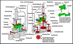
Fig. 1: Principle of the first Lambach pump

Fig. 2: Function of the pump

Fig. 3: Function of the pump


The first design of a Lambach pump (single-acting, standing, ie vertical piston movement) is shown in Figure 1. The working and pressure cylinders of the pressure transducer are connected by three columns. The double piston is provided with a lifting piece secured against rotation by means of a column, in which there is a lifting pin that engages under a cam piece. The cam piece and hammer are firmly connected to a shaft that can rotate in a crossbeam attached to two columns. The angle lever, to which two buffers are attached, can be rotated around a second shaft in the traverse. Both waves are offset from one another in the vertical direction. Two stops limit the movement of the angle lever, in that one of its buffers touches a stop. The movement of the angle lever is transmitted to the switching lever of the inlet and outlet valve via tie rods, whereby perforated valve plates are rotated against each other and the valves are opened or closed (rotary slide valves). The feed line to the pressure cylinder branches off from the drive and delivery water line leading to the inlet valve via a check valve (RSV). The pressure cylinder is also connected to the riser leading to the point of use via an RSV.
The function of the pump is shown in Fig. 2 and Fig. 3. When the pump is started up, the water flows from the reservoir, which is higher than the pump, into the valves and the working cylinder. It is not known whether and, if so, how an initial venting took place. The water flows through the opening lower RSK via the feed line into the pressure cylinder, opens the RSK there and rises in the riser to the level of the reservoir. The pressure in the working cylinder generates a large force due to the large piston area, which results in a high pressure in the pressure cylinder due to the small area of the piston there. This creates a brief backflow through the lower RSV, which closes it. Water is now pressed into the riser at high pressure. During the upward movement of the double piston, the lifting pin rotates the cam piece and thus the hammer. As soon as this has exceeded its highest position, it falls down due to its weight and hits a buffer of the angle lever. As a result, it is rotated very quickly and switches over the valves via the tie rods and the switch lever. The double piston stops and now moves downwards because of the water flowing out at the outlet valve and the associated negative pressure in the working cylinder. The pressure in the pressure cylinder also drops and the water flowing back briefly from the riser closes the RSV there. Water is sucked in via the feed line so that the lower RSV opens. As the piston moves downwards, the lifting pin now presses from above on the cam piece, which in turn raises the hammer (in the opposite direction), falls down and thus causes the valve to switch again. The cycle starts all over again. The water in the riser is now higher than the reservoir level and is raised a little further with each cycle until it flows out intermittently at the point of consumption. A cycle takes a very long time (60 to 120s). All Lambach pumps are slow runners.
This construction was modified very soon while keeping the principle. The inlet and outlet valves are now combined in one housing and are switched using a common hammer-operated lever (but now with the help of gear segments). Two chains guided over deflection wheels connect the double piston with a counterweight. When the piston is lowered (filling the pressure cylinder, emptying the working cylinder) the weight is raised and part of the energy otherwise lost during this process is stored as potential energy. When starting up (water is pressed into the riser), the weight, in addition to the water pressure, exerts an additional force on the double piston. In this way, a higher degree of efficiency is achieved and higher pressures (delivery heads) can be achieved.
Principle of a horizontal, double-acting Lambach pump
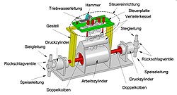
Fig. 4: Principle of a horizontal, double-acting Lambach pump
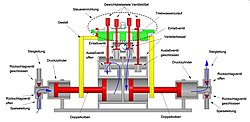
Fig. 5: Section through the pump

Fig. 6: Valve control

Figure 7: Valve control (animated)


The function of all Lambach pumps is basically the same as described above. Only the arrangement of the pressure transducers and the valve control as well as the specific structural design differ. In the following, an embodiment with a horizontal direction of movement of two coupled pressure transducers working in push-pull mode is described (double-acting, lying). Thanks to the push-pull principle, an almost even flow is achieved at the point of use.
The two double pistons are connected to one another with a frame that is guided in a control plate (see Figures 4 and 5). Designs are also known in which the two double pistons are also directly connected to one another (via a piston rod). The two pressure cylinders are provided with feed lines (drinking water) and risers via RSV. The feed line coming from the drinking water reservoir branches before, while the risers are brought together behind the pump. Two distributor vessels containing the inlet and outlet valves and supporting the control plate are arranged above the working cylinder. The penstock leads into the upper distributor tank. In the sectional view, the double pistons move from left to right. The valve positions and the water flow are shown. The motive power flowing out of the outlet valves drains off via the outer wall of the two connected working cylinders (or via drainage channels located below the outlet valves).
The valve reversal is initiated by two stops fixed in the frame (Fig. 6). The valves are lift valves, the weights of which are dimensioned in such a way that they also close reliably against the pressure prevailing in the working cylinder. When the double piston (and thus the frame) moves to the right, the left stop hits the rack A, which is slidingly mounted in the control plate, and moves it. As a result, the gear A connected to the selector shaft is rotated and the hammer attached to the selector shaft is raised. A gear wheel B runs loosely on the selector shaft. It only rotates when the driver pin in the selector shaft hits the stop pin connected to gear B. As soon as the hammer has passed its highest point, it falls down, causing the gearshift shaft to rotate rapidly via gear A. The rack A is moved from the left stop in the direction of the right stop. The gear wheel B now rotates and moves the cam carriage, which is slidably mounted in the control plate, with the aid of the rack B, which is attached to the cam carriage. The switching cams lift valves 2 and 4 (i.e. open them), while valves 1 and 3 fall back into their sealing position. The switchover is complete.
Lambach pumps in Germany (selection)
- “Lambach pump” in the “Däfernwald” of the hamlet of Däfern near the Auenwald community (Baden-Württemberg), supplied the high hamlet of Lutzenberg with water from 1929 to 1958 . The E300 pump, built in 1929, was in operation until 1954 (or 1958?) And is a listed building. It had a delivery head of 130 m. The floating water column was 30 m high. The facility was restored in 2008–2011.
- Weilmünster-Rohnstadt : The L380 pump, built in 1921, was in operation until 1964. The delivery rate was 1250 l / h.
- Marienheide : A functioning pump of the type L380, built in 1911, will be demonstrated in the Lambach pump museum.
- Lykershausen : The old water pump was built in 1925 and was in use until 1968. It is of the 380L type, has a delivery rate of 1500 l / h and a delivery height of 116 m.
- Konz : A non-functional Lambach pump is in a reconstructed pump house in the folklore and open-air museum Roscheider Hof .
- In the Walldürner district of Hornbach (Neckar-Odenwald district), a Lambach pump L380 from 1924 was restored to working order in 1995 and the machine house from 1894 was renovated.
- Nomborn in the Westerwald: A Lambach pump is still operated to supply the local wells.
- Blankenheimerdorf : A no longer functional D500 pump from 1929 is to be restored.
- Much in the Rhein-Sieg district: In the "water park" of the Technology and Farmers Museum in Much Berzbach there is a functional Lambach pump of the L380 type, built in 1914.
Lambach company, its owners and some machine data
Quoted from oberwipper.de :
- Gottlieb Lambach (* 1838 in Griemeringhausen near Marienheide ; † 1921/1922?), Trained mill builder, inventor of the Lambach pump around 1880. Founder of a machine factory in Marienheide-Oberwipper, OT Oberwipper.
- Wilhelm Lambach sen., B. 1875, son of Gottlieb Lambach, took over the machine factory in 1912 and ran it until his death in 1944.
- Wilhelm Lambach jun., B. July 21, 1903, son of Wilhelm Lambach senior, temporarily active in the company as operations manager. Career as a technical officer in the Reich and Federal Air Force and as a consulting engineer in engine technology. Died in 1992.
Under Wilhelm Lambach jun. the company had ten employees and delivered machines to many countries. The delivery rate ranged from 30 to 300 cubic meters per day, depending on the model. According to brochures, the selling prices of the machines in the 1930s were between 3700 and 11300 RM (Reichsmark). Drive gradient (and delivery gradient) ranged from 2.5 to 150 (or 180) meters. Depending on the type, a machine weighed between 800 and 7800 kilograms. The overall water pumping efficiencies of these various machines were between 50 and 90%, often between 65 and 80%.
Types of Lambach pumps
Data cited from oberwipper.de .
- Type E280 (S), upright piston, 15 cubic meters / day, at least 60 m delivery head, construction from around 1900, 1897 at the earliest
- Type E300, upright pistons, 30 cubic meters / day, 2.5–50 m (2.5–50 m) drive gradient (and delivery gradient), construction from 1909 at the latest
- Type E400, upright pistons, 45 cubic meters / day, 3–60 m (3–60 m) drive gradient (and delivery gradient), construction from 1922 at the latest
- Type L380, horizontal pistons, 270 cubic meters / day, 4–150 m (3–180 m) drive gradient (and delivery gradient), construction from 1911 at the latest
- Type L500, horizontal pistons, construction since 1961 at the latest, last developed Lambach type
- D280, upright pistons, at least 12.2 cubic meters / day, delivery height at least 59 m, construction from 1911 at the latest
- Type D400, upright pistons, at least 26.6 cubic meters / day, at least 75 m delivery head
- Type D500, upright pistons, 300 cubic meters / day, 4–80 m (3–90 m) drive gradient (and delivery gradient), construction since 1922 at the latest
See also
literature
- Peter Wagner: The history of the Lambach machine factory and the Lambach pumps. Published by Lambach-Pump Marienheide eV, 2014.
Web links
- Animation of the functional principle (youtube video)
- Company history and schematic drawings
- Original company brochure 1950 (PDF)
- Description of the Lambach pump in the Roscheider Hof open-air museum
Individual evidence
- ↑ Water column machine . In: Brockhaus Konversationslexikon . tape 16 . Leipzig January 1903.
- ↑ Duisburger Maschinenbau-Actien Gesellschaft: water column machine with pump for delivery heights that exceed the gradient. (PDF) September 30, 1878, accessed on September 3, 2019 (after calling up , click on "Open entire document").
- ↑ Duisburger Maschinenbau-Actiengesellschaft: water column machine with pump for delivery heights which are lower than the usable gradient. (PDF) March 1, 1879, accessed on September 3, 2019 (after calling “Load complete document”).
- ^ Anonymus: Duisburg water column pump. In: Polytechnisches Journal . tape 236 , 1880, pp. 282–283 ( dingler.culture.hu-berlin.de [accessed September 3, 2019]).
- ↑ Anonymous: water column pump from C. Körber in Stuttgart . In: Polytechnisches Journal . tape 243 , 1882, pp. 18-20 ( dingler.culture.hu-berlin.de [accessed September 4, 2019]).
- ↑ C. Körber: Combined water power machine and pump. (PDF) February 20, 1881, accessed on September 4, 2019 (click on “Load complete document” after calling up).
- ^ Maschinenfabrik Wilhelm Lambach: prospectus. (PDF) Retrieved September 3, 2019 .
- ↑ Lambach pumps, contents. Retrieved September 3, 2019 .
- ↑ Gottlieb Lambach: Self-Acting Pump. (PDF) October 3, 1895, accessed on September 3, 2019 (click on “Load complete document” after calling up).
- ↑ Gottlieb Lambach: Self-Acting Pump. (PDF) October 3, 1895, accessed on September 3, 2019 (click on “Load complete document” after calling up).
- ↑ Gottlieb Lambach: Double pump coupled with a water column machine. (PDF) September 4, 1906, accessed on September 3, 2019 (click on “Load complete document” after calling up).
- ^ Museum and Memorial Lambach Pump. In: marienheide.de. Marienheide parish, accessed on April 29, 2019 .
- ^ The Lambach pump in the Roscheider Hof open-air museum
- ↑ The Lambach pump from Nomborn, the village of fountains
- ↑ The Lambach pump in the Haubachtal
- ↑ Information on the Technology and Farming Museum
- ↑ oberwipper.de
- ↑ oberwipper.de (PDF).