
Hydraulic ram

A hydraulic ram , the ram pump , back pressure water fountain or water ram is a water-driven, intermittently operating pump . The ram uses the pressure surge or dynamic pressure effect to raise some of the water that drives the pump to a higher level. It is particularly suitable for pumping tasks in the vicinity of rivers with a gradient sufficient for operation.
A Lambach pump fulfills the same purpose , but in contrast to a hydraulic ram, it does not work with the kinetic energy of the water, but with the potential energy . It is not the flow rate that is used, but the water pressure . Lambach pumps are no longer built. They were much more expensive than hydraulic rams.
Areas of application
For agriculture, mountain huts and holiday homes, which are located near flowing water, rams are often used for water supply. Most of these are properties in remote areas that are neither connected to the public water supply nor to the public electricity network or are only used temporarily for other reasons.
New hydraulic rams are used particularly in development aid. For example, there is an application of hydraulic rams in southeastern China for small-scale agriculture as an alternative to diesel pumps.
history

The hydraulic ram is the automation of 1772 by John Whitehurst invented pulsation engine , when caused by the closing of a faucet water tower vibration raises a water column over the height of the influx. Repeated opening and closing of the tap raised large amounts of water. In 1796, the Frenchman Joseph Michel Montgolfier replaced the faucet of the pulsation engine with a valve that closed again automatically and developed the hydraulic ram together with Aimé Argand . The name should also come from Montgolfier, because he wrote in his patent specification that when the valve closes, a force arises “like the impact of a ram”.
The hydraulic ram is mentioned for the first time in the Académie des Sciences record of July 14, 1797. The “citizen” Montgolfier had given a lecture entitled Sur un moyen très simple d'élever l'eau des fleuves (“About a very simple means of lifting the water of rivers”). The French patent for the invention was granted in November 1797. For England, the patent (number 2207) was granted on December 13, 1797 to the steam engine pioneer Matthew Boulton , who filed the application in his name for Montgolfier.
The first hydraulic ram in Germany was installed by the technical scientist Joseph von Baader (1763-1835) at the beginning of the 19th century to supply water to the country estate of Count Montgelas in Bogenhausen near Munich.

The first American patent was granted to J. Cerneau and SS Hallet in 1809. In the United States , interest in hydraulic rams increased sharply from around 1840 when more patents were granted and local companies started production .
One of the first manufacturers in Switzerland was Johann Georg Schlumpf , who sold the first hydraulic ram in 1885. In 1923 he developed "self-ventilation". This automatically filled the air cushion on a regular basis, which made maintenance-free operation possible for decades.
It was not until the middle of the 20th century that interest declined again when the use of electricity and thus electric pumps spread.
The Swiss company Schlumpf Innovations has been developing the self-ventilated hydraulic ram by Johann Georg Schlumpf since the 1990s . In the meantime, delivery heights of up to 500 m and delivery rates of up to 15,000 liters per day can be achieved. This is achieved by improving the valve technology and timing as well as winding the drive line with subsequent concreting in a compact concrete block in order to absorb the high, shock-like pressure loads.
Structure and functional description
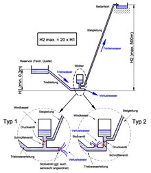

A hydraulic ram consists of the following elements:
- A sufficiently abundant water catchment as a storage container (at a low height),
- the penstock ,
- the high-pressure-resistant and stiff water flow pipe with a valve set at the end, consisting of
- the shock valve, which abruptly stops when a certain flow is reached and
- the pressure valve, which briefly lets a little water escape at high pressure in
- the "air tank" as a buffering pressure vessel, and
- the connected riser (up to a greater height).
Together, these components form a pulsating system which, after a single push, continues to work independently, as long as there is sufficient water supply. Since the system has only two moving parts (shock and pressure valve), production can be cost-effective, maintenance is simple and the unit is extremely reliable, assuming the valves are not soiled.

From a storage tank that is fed by a spring or a stream, water flows through a drive line that is not too short and, for the most part, exits through the shock valve (on the ram) as lost water into the flowing water.


The function of the shock valve depends on the setting of the valve gap. This is shown schematically in the picture below. The shock valve is held open by a spring or weight. If there is a large gap, the water can flow off without affecting the valve. If the (small) gap is set correctly, other conditions arise (see also). The pressure p1 and the flow velocity v1 prevail in the headwater in front of the valve. Because of the narrow gap, however, the water in the valve flows at a much higher speed v2 (law of continuity ). According to the laws of flow ( Bernoulli ), a negative pressure p2 arises in the valve (this is largely dependent on the flow velocity). As a result, the valve is closed against the force of the weight or the spring due to the force resulting from the pressure difference p1-p2. In practical operation, the valve opens periodically, so that each time there is a very rapid increase in the flow rate in the valve, with the consequence of a sudden increase in the pressure difference. In this way the valve closes suddenly.
The flow of water flowing in the drive line up to this point is suddenly blocked. The water mass reacts to this with a huge increase in pressure, which leads to the deflection of the flow (towards the air chamber) and to the opening of the pressure valve (check valve).
The motive water flows into the air chamber and compresses the air there until the counter pressure (caused by the compressed air) reverses the direction of flow and closes the pressure valve again. By closing the pressure valve, a negative pressure surge is initiated, which can now spread in the penstock.
The part of the water that remains under high pressure in the air chamber is pressed into the riser until the pressure of gravity in the riser and the pressure of the compressed air (which decreases due to expansion) are equal. The water in the riser (conveyed water) is thus raised a little with each pumping cycle according to the volume supplied, so that it flows out in a pulsating manner at the end of the line (point of consumption). In this way, water pressures of up to 50 bar can be generated, which correspond to delivery heights of up to 500 m. Typical gradient heights of the penstock are between 30 cm and 5 m. Experiments have shown that the ratio of head to headline length should be between 1: 3 and 1:12.
The cycle time (frequency) of the pump is determined in particular by the duration of the acceleration of the headwater from the opening to the closing of the shock valve and the period in which the pressure valve is open (see diagram below). Typical are 0.5 to 2 seconds per cycle. The vibration phenomena described below take place in the millisecond range and have no influence on the cycle time. When the shock valve is opened (triggering a new cycle) the headwater rests and only the gravitational pressure of the water acts on the shock valve (according to the headwater head). The valve weight or the valve spring are dimensioned so that the valve is opened against this pressure. The opening is triggered by the above-mentioned negative pressure surge after the pressure valve has closed.
Automatically controlled by a valve, the system divides a step-by-step flow of water (head water) at low pressure by periodically changing diversions from a smaller amount of conveyed water that is under high pressure and also moves step-by-step (upwards). The hydraulic ram therefore represents a pressure transducer .
The ram is also referred to as a piston pump without a piston , as the water flowing into the air chamber and braked there takes on the function of a "piston" which pushes the water already there into the riser.

Water flows through the drive line (1) and exits at the shock valve (2) opened by the weight (4).

The shock valve (2) closes due to the water pressure, the rising pressure opens the pressure valve (5), water flows into the air chamber (6)
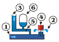
Counterpressure of the air chamber (6) closes the pressure valve (5), water from the air chamber is pressed into the riser (3)


Pressure surge calculation and pressure curve
Estimation with the Joukowsky equation
The Joukowsky equation is often used to estimate the pressure surge in the hydraulic ram . This was created in order to determine the extreme case endangering the pipelines when a valve suddenly closes or opens.
For the sake of simplicity, it is assumed that the flow (volume flow) and the flow speed through the valve do not change during the closing process and only assume the value zero after the valve has completely closed. This is equivalent to a valve closing time = 0. However, the Joukowsky equation does not provide an infinitely large pressure jump, since the compressibility of the water was taken into account in the derivation of the equation.

For the derivation of the Joukowsky equation and for further explanations, see and.

in which:
-
= Pressure change in N / m², = density in kg / m³ (water: 1000 kg / m³), = wave propagation speed in m / s (water: approx. 1000 m / s) and = speed change m / s.


The Joukowski shock is the maximum possible pressure increase. The pressure surge (deceleration of the flow velocity to zero) propagates from the surge valve with velocity c and is “reflected” at the reservoir, ie the pressure in the line now creates a flow in the direction of the reservoir. This relaxation wave, which also moves at speed c, reaches the shock valve again after a certain running time and there generates a negative pressure due to the inertia of the water mass. The real valve closing time therefore only has an effect if the negative pressure surge arrives at the surge valve before it closes completely and weakens the pressure there.
The sum of the transit times from the shock valve to the reservoir and back is called the reflection time T r of the pressure wave.
- = the length of the pipeline [m]


For example, if water flows at 3 m / s through a 5 m long pipe, the reflection time = 10 ms (milliseconds) and the pressure rises briefly to 30 bar with a valve closing time of = 10 ms (an even shorter closing time has no further pressure increase result!).

There is an approximation with which the influence of the real closing time on the pressure surge can be roughly estimated:

( )

in which:
- the closing time of the valve [s]
and
- the reflection time [s]
is.
The estimate of the pressure surge that actually occurs using the Joukowsky equation, taking into account the closing time of the shock valve, provides values that are too high. An approximate determination of the pressure surge with the pulse rate is more useful.
Estimation with the law of momentum
Unlike the Joukowsky shock, it is not assumed that the flow velocity does not change until the shock valve is completely closed. Rather, the mass of water to be braked and the speed reduction (negative acceleration) determined by the closing characteristics of the valve are used as a basis.


m flowing water mass
F Force on the cross-sectional area of the penstock
A Cross-sectional area of the penstock
L Length of the penstock
Density of water

Decrease in speed when closing the shock valve

(see also "Theory of the rigid water column" in and)
In the example given above (length of the penstock L = 5 m, a valve closing time of = 10 ms and a flow velocity of = 3 m / s), assuming a linear closing characteristic ( = 300 m / s 2 ), a pressure surge of 15 results bar. This is a more realistic value than that determined with the Joukowsy equation, which applies regardless of the length of the headrace.


For long headwaters, the momentum theorem provides even larger values than the Joukowsky equation, which gives the maximum possible pressure surge, because the compressibility of the water (rigid water column) is not taken into account. Both methods represent only estimates, neglecting various influencing factors. For a more precise calculation, the "theory of the elastic water column" should be used (see cited literature).
It should be noted that the flow is only stopped by the pressure surge with regard to its original direction of flow, which leads to a diversion in the direction of the air chamber. This does not interrupt the flow and approximately maintains its inherent kinetic energy.
Pressure propagation
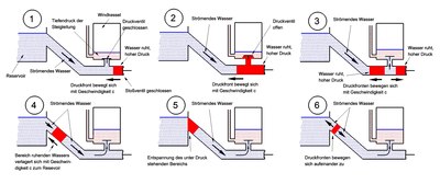
Pressure propagation

Spread of the negative pressure
After closing the shock valve (1), the water in front of the valve is slowed down to zero speed, while it continues to flow in the drive line.
At first glance this is incomprehensible. It can be explained if one takes into account the low flow velocity and the compressibility of the water compared to the much higher wave propagation velocity. For example, the water at the headwater inlet at the start of the pressure surge and flowing at 3 m / s moves only 15 mm from the shock valve to the reservoir for a 5 m long pipe (running time 5 ms) during the runtime of the pressure wave.
The pressure front moves with the speed c in the direction of the reservoir. and also spreads in the direction of the air chamber. The pressure valve is opened (2). The water flows into the air chamber, whereby, starting from the pressure valve, a relaxation front spreads, which also moves with c to the reservoir and to the shock valve. The water, which is still before it flows into the air chamber, is accelerated by the relaxation of the two pressure zones (on the side facing the air chamber) (3). The pressure front facing the reservoir continues to stop the water. The relaxation on the air vessel side is thus offset by compression on the reservoir side. Both fronts move towards the reservoir with c. This means that a zone of still water moves with c through the headrace pipe (4). Strictly speaking, the water only rests in the middle of the zone, as there is a constant outflow and inflow.
When this pressure zone has reached the reservoir, the reflection takes place, ie the water no longer flows into the reservoir side, but out of the pressure zone (5). The fronts move towards each other and the pressure zone dissolves. The water continues to flow into the air chamber (6), driven by the deep pressure, at a decreasing speed, until the pressure valve begins to close when the pressure is equalized. There is a return flow from the air chamber to the reservoir (7).
After the pressure valve closes suddenly, a negative pressure zone is created behind the valve, the fronts of which again expand with c (8). After a front has reached the shock valve, it begins to open (9). Air is sucked in so that the water can condense (volume reduction) and take on atmospheric pressure (the air takes care of the volume compensation). This is equivalent to an inflow of water into the negative pressure zone, combined with a front displacement taking place at speed c (10). The inflow takes place in the vicinity of the negative pressure front, while the water is already at rest in the area towards the shock valve.
As in the case of pressure propagation, a zone of still water (negative pressure) now moves through the headrace line at speed c, since the inflow on the shock valve side is opposed to an outflow with c on the reservoir side.
After the negative pressure zone has reached the reservoir, it is reflected. There is an inflow on both fronts of the zone, which leads to the disappearance of the negative pressure zone (11). The water, which is now at rest, is accelerated by the deep pressure and exits at the open shock valve until it closes again (12).
Pressure curve
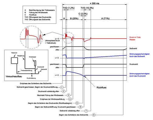
Only a few metrological studies on the hydraulic ram are known. The following description is based on the publication.
The diagram opposite is based on this discussion. Characteristic processes are shown, with overlapping (higher frequency) vibrations being eliminated. These additional pulsations are traced back to pipe elasticities and to reflections of the pressure wave at the reservoir without further analysis.
The pressure surge (1) occurs after the surge valve closes. The pressure valve opens very quickly and reaches its end position (2), where it suddenly stops. The water flowing into the air chamber experiences an abrupt change in resistance through the valve, so that a secondary pressure surge occurs. Due to the inertia of the flowing mass, the water flowing further into the air tank briefly creates a negative pressure (3) in the headwater without opening the shock valve. This is important for the continuous use of the ram, as the negative pressure pulls in outside air via a sniffer valve or a small hole. The bubbles rise upwards, which means that the air supply in the air chamber is refilled with every pressure surge. When the pressure valve is open, a pressure oscillation (4) occurs as a countermovement. The water flows further into the boiler, driven by the gradient of the drive line. The now low water pressure in the headwater is not causally involved (the pressure surge only serves to quickly open the pressure valve and is therefore not a measure of the achievable delivery head). Rather, it is the kinetic energy of the flowing headwater (which is stopped in the air tank) that creates the pressure on the water in the air tank and thus ensures that it is filled again. The force F W (or the pressure F W / A W ) on the valve cross-section A W and thus on the water in the air tank is approximately calculated according to the above equation:


F W Force on the valve cross-section of the pressure valve
Pressure on the pressure valve

Cross-sectional area of the pressure valve

Inflow velocity into the air chamber

Decrease in speed when flowing into the air chamber

For example, for L = 5 m, A = A W (line cross-section corresponding to the valve cross-section), = 3 m / s (initial speed for the air vessel inflow), inflow time 0.1s (pressure valve open) and consequently = 30 m / s 2 ( Assuming linearity) a value of = 1.5 bar. The maximum achievable delivery head is therefore 15 m. The inflow time depends, among other things, on the air volume and the pressure (depth pressure of the riser pipe) in the air chamber.
At (5) the pressure valve begins to close because of the back pressure now present in the air chamber, with a return flow from the air chamber in the direction of the water reservoir. This return flow is abruptly interrupted when the valve is completely closed, so that a negative pressure (6) occurs because the water tends to flow further in the direction of the reservoir due to its inertia and is prevented from doing so by the closed valves. The negative pressure triggers the opening of the shock valve. The actual opening takes place through the force of the spring or the weight of the valve. The headwater flows through the valve at increasing speed. When the valve reaches its end position (7) (fully open), there is a brief pressure increase in the same way as with the secondary pressure surge (2) at the pressure valve. After the headwater in the valve has reached a speed that results in a sufficient pressure difference across the valve, the shock valve (8) closes and a new cycle begins.
Special applications
With the help of a series connection of several rams, large delivery heights can also be achieved. However, the amount of water pumped decreases with each stage because only about 10% of the water flowing through is pumped on.
Using so-called “wild water rams”, different waters can also be used for ram drive and water pumping. For example, the ram can be operated with surface water, while the drinking water to be pumped from a well is separated from the headwaters by an elastic membrane. The pressure surges of the headwater drive a kind of attached membrane pump .
There is a certain degree of comparability to the Lambach pump , in which, however, it is not the kinetic energy of the water, but the potential energy (water pressure) that causes the water to be pumped. Here there is also the option of separating the water for propulsion from the pumped water, so that, for example, water of inferior quality can also be used as driving water.
Typical operational problems
Typical operational problems are air in the drift line, blockage of the water supply or the valves or freezing in winter.
Too little air in the air chamber can be avoided by using a small air valve (1–2 mm hole) or a sniffer valve just in front of the check valve (pressure valve). A little air is sucked in with each stroke and pushed into the boiler.
Shock noises
Another problem is the considerable noise emissions during pressure surges. In residential or natural areas, they require noise protection measures. The parts of the structure exposed to the impact are mostly made entirely of metal due to the forces involved, which means that the impact noises are also transmitted to the drive line and riser. As a countermeasure, the installation of (short) pieces of plastic pipe at or near the pipe ends going from the ram is used. In this way the propagation of the noise through the pipes is significantly reduced. Further options are classic noise protection such as covering with sound insulation and - especially in living areas - underground installation.
Hydraulic ram as an alternative model for cardiac physiology
In simplified terms, it is usually taught that the heart acts as a pump and drives the bloodstream . This model neglects the observation that the bloodstream during embryological development begins before heart development, and conflicts with observations in the cardiac intensive care, which increasingly takes into account the active role of the circulation periphery of the bloodstream with to successful results in the treatment of heart failure to come. The American cardiologist and intensive care physician Branko Furst therefore asks whether the hydraulic ram model does not describe the cardiovascular function better than the conventional pump model.
Comparison with electrical circuit

The hydraulic ram also has an electrical analog that is used much more frequently: the step-up converter , which can generate considerably higher voltage peaks in pulses from a low DC voltage . The following correspond to:
- Inductance L = inert mass of the water in the penstock
- electrical current in the inductance = current of the water in the penstock
- Switch S = shock valve
- Rectifier D = pressure valve
- Condenser C = air vessel
- Voltage U E and U A = height differences of the different water levels
Locations
See also
literature
- Christian Mähr : The hydraulic ram in: Forgotten inventions. Why doesn't the soda locomotive work anymore? New edition, Dumont, Cologne 2005 (first edition 2002), ISBN 978-3-8321-7744-7 , pp. 65–80 (also in Weltbild 2005 as ISBN 978-3-8289-5398-7 ).
Web links
- Video: Hydraulic Ram (French)
- hydraulische-widder.de Information about the mode of action and the history of the hydraulic ram, as well as the Widder Museum with a collection of different rams.
- hydraulischer-widder.ch Information about modern hydraulic rams
- Ueli Gutknecht: How water pumps water (PDF)
- Water tower Tauchersreuth (historical water supply system with hydraulic ram)
- turneralp: how to make a hydraulic cylinder youtube.com, March 3, 2015, video (4:51) - DIY production of a ram
Individual evidence
- ↑ Hydropower for China ( Memento from September 27, 2015 in the Internet Archive ) www.atmosfair.de, undated, last accessed May 2, 2017.
- ^ Mathias Döring 2500 years of energy from water , communications from the Chair of Hydraulic Engineering and Water Management at RWTH Aachen University, Issue 167, Shaker Verlag, Aachen, 2013
- ↑ Schlumpf Innovations: Compact Aries. Retrieved March 1, 2015 .
- ↑ AN ASSESSMENT OF THE IMPACT OF THE IMPULSE VALVE ON THE PERFOMANCE OF A HYDRAULIC RAM (by Dumisani Siwinda) | Pump | Mechanical engineering. Retrieved February 17, 2018 .
- ↑ Johann Albert Eytelwein: Remarks on the effect and advantageous use of the ram (Bélier hydraulique): together with a series of experiments with different arrangements of this new water lifting machine . Realschulbuchh., 1805 ( limited preview in Google book search).
- ↑ DEPATISnet | Document DE000000842450B. (PDF) Retrieved February 2, 2018 . Attention! With DEPATISnet information, an error message often appears the first time it is clicked. The second time the link works.
- ↑ Lang, Stache: Hydraulics of pipe systems . Ed .: Institute for Hydromechanics Karlsruhe. S. 95 ( uni-karlsruhe.de [PDF]).
- ↑ KSB (ed.): The pressure surge . ( ksb.com [PDF]).
- ↑ G. Wossog: Manual pipeline construction . tape 2 . Vulkan-Verlag, Essen 2003, ISBN 3-8027-2723-1 .
- ^ Jürgen Giesecke, Stephan Heimerl, Emil Mosonyi: Hydropower plants: planning, construction and operation . Springer-Verlag, 2014, ISBN 978-3-642-53871-1 ( limited preview in Google book search).
- ↑ Gerhard Bollrich: Technical hydromechanics 1: Fundamentals . Beuth Verlag, 2013, ISBN 978-3-410-23481-4 ( limited preview in Google book search).
- ↑ WALLACE M. Lansford, WARREN G. DUGAN: AN ANALYTICAL AND EXPERIMENTAL STUDY OF THE HYDRAULIC RAM . Ed .: UNIVERSITY OF ILLINOIS. January 21, 1941.
- ↑ SB Watt: A MANUAL OF INFORMATION ON THE AUTOMATIC HYDRAULIC RAM FOR PUMPING WATER . Ed .: Intermediate Technology Development Group Water Development Unit, National College of Agricultural Engineering, Silsoe, Bedford, MK45 4DT, UK January 10, 1974 ( ircwash.org [PDF]).
- ↑ C. Verspuy, AS Tijsseling: Hydraulic ram analysis . Ed .: Delft University of Technology. ( tue.nl [PDF]).
- ↑ W SOBIESKI, D Grygo, S LIPINSKI: Measurement and analysis of the water hammer in ram pump . In: Indian Academy of Sciences (ed.): Sadhana . Vol. 41, No. 11 ( ias.ac.in [PDF]).
- ↑ Branko Furst: The Heart: Pressure-Propulsion Pump or Organ of Impedance Journal of Cardiothoracic and Vascular Anesthesia 2015; 29 (6): 1688-1701. PMID 26026358 , full text
- ^ Branko Furst: The Heart and Circulation: An Integrative Model . Springer, New York 2013. ISBN 978-1-4471-5276-7 . Pp. 145, 147–153, 186, 218. (PDF see: http://medfac.tbzmed.ac.ir/uploads/3/CMS/user/file/10/library/books/heart%20circulation.pdf )
- ↑ Markus Meier: The hydraulic ram . In: Electronics technician . No. 6 ( bioconsult.ch [PDF]).
- ↑ Electronic boost converter and hydraulic ram . In: University of Stuttgart, Institute for Power Electronics (Ed.): Basic internship . ( uni-stuttgart.de [PDF]).