
Melbourne Express
 Melbourne Express general plan
|
||||||||||||||||||||||||||
|
||||||||||||||||||||||||||
|
||||||||||||||||||||||||||
|
||||||||||||||||||||||||||
|
||||||||||||||||||||||||||
The Melbourne Express of the Hapag-Lloyd shipping company was the largest container ship in the world in 1970 . The ship was able to carry a total of 1,526 TEU , 92 of which were refrigerated containers . Before the merger of the two shipping companies Norddeutscher Lloyd (NDL) in Bremen and Hamburg-Amerikanische Packetfahrt-Actien-Gesellschaft (HAPAG) in Hamburg, the ship was ordered to form Hapag-Lloyd AG.
history
The Melbourne Express was commissioned by the NDL at Bremer Vulkan as construction number 956 at the end of April . The keel was laid in December 1969, launched in April 1970 and delivered to Hapag-Lloyd on September 5, 1970.
In the Experimental Institute for Hydraulic Engineering and Shipbuilding (VWS) in Berlin , tow tests were carried out with the model of the ACT 1 due to the line changes required for the Melbourne Express at the ends of the ship . The cavitation tests were carried out in the Hamburgische Schiffbau-Versuchsanstalt and the sea state and wind tunnel tests in Wageningen in the Netherlands and in the Hermann Föttinger Institute at the TU Berlin .
Ship description
The Melbourne Express corresponded in many respects to the new ACT 1 building , which the Bremer Vulkan had already given to the British Associated Container Transportation Ltd. had delivered. The ACT 1 had spaces for a total of 1223 TEU, including 326 reefer containers (R-TEU), the Melbourne Express for a total of 1526 TEU, but with 92 R-TEU, significantly fewer reefer containers. Since at the time in the Australian service, in which the ship was deployed, porthole containers were driven below deck with ship-mounted cooling devices, more space was required for this.
With a length over all of 217.9 m, width on frames of 29 m and a side height of 15.3 m, the ship had a measurement of 25,558 GRT and a deadweight at summer freeboard draft of 11.51 m of 31,610 dwt. With the nominal power of 32,450 hp, the Melbourne Express reached 23 knots on the test drive . The engine room was at the very back and holds 1 to 11 in front of it. Hold 10 was insulated; the cooling rods for the refrigerated containers were located here. In holds 6 to 9, eight containers could be driven side by side and six on top of each other. In holds 1 to 5 as well as 10 and 11 there were restrictions due to the shipping lines in the lower area. In room 11 directly in front of the engine room, only three containers could be stowed in the rear area. The lower area of the room belonged to the engine room. 40-foot containers could also be driven in rooms 4 to 9. In total there was space for 840 containers in the rooms and 626 containers on deck. On deck, the number of containers was limited in height by the sight beam , on the hatch covers of rooms 2 to 9 three and on those of rooms 10 and 11 four containers could be driven one above the other and up to eleven containers side by side. On both sides of the ship, under the main deck, there was a service corridor from the engine room to the forecastle, which allowed the cargo holds to be accessed.
The ship received a fin stabilization system with retractable fins, each with an area of 7 m² from AEG-Schiffbau, which was able to reduce the roll angle from 46 ° to 10 °. For problem-free loading and unloading of the containers, the Melbourne Express received a heeling compensation system, which consisted of side tanks No. 8 port and starboard. The tanks were provided with a cross line and connected to the ballast water system. This enabled the maximum permissible heel angle to be maintained when loading and unloading. The ship's stability under the various loading conditions was adjusted with the ballast water system.
The crew consisted of 40 people, 11 officers, 14 non-commissioned officers and 15 crew ranks, all of whom were accommodated in individual cabins.
mechanical engineering
For optimum layout of machinery, boiler and auxiliary boiler turbo and diesel generators, auxiliary equipment, heat exchangers and pipes one was the engine room model created.

A gear turbine system from Stal Laval, built under license at Bremer Vulkan, served as the main drive system . The turbine, the main condenser, the gearbox and the thrust bearing were all in one plane. The two Foster-Wheeler boilers built at Bremer Vulkan with a nominal output of 50,000 kg of superheated steam at 514 ° C at 64 bar per hour were arranged above the thrust bearing and the shaft line . The drive system was operated from the air-conditioned control room in the machine area or from the bridge. As with the ACT ships, a scoop capacitor was installed.
Reefer container
As was common in the Australian service at the time, the refrigerated containers did not have their own aggregate, but 20-foot porthole refrigerated containers were driven. The refrigerated containers were insulated on all sides, had two round openings for air entry and exit on the face opposite the door, were all 8'-6 "high so that the flexible, extendable couplings of the air cooling system of the cooling rods fit at the level of the air openings Refrigerated containers were arranged in four groups each with 23 refrigerated containers in hold 10.
The cooling rods were arranged horizontally in the ACT ships, whereas on the Melbourne Express they were arranged vertically, ie one temperature could be maintained for the six reefer containers per cooling rod. The cooling temperature per cooling rod could be set in the range of −20 ° C to +12 ° C. The fans of the cooling rods were designed for the 45-fold air exchange of the containers. A total of three Grasso refrigeration compressors with condenser and brine cooler were used to generate the cold. R22 was used as the refrigerant . The brine flowed through the coolers in the cooling rods, and the air temperature was set with brine mixing valves. A steam-heated brine heater was available for defrosting.
Gallery 1

Horizontal cooling rods, ACT ships

Vertical cooling rods, Melbourne Express
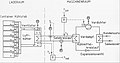
Porthole container system in the ship


literature
- Several authors: Turbine container ship "Melbourne Express". In: Schiff und Hafen , issue 11/1970 22nd year.