
Mercedes-Benz OM 352
| Daimler Benz | |
|---|---|
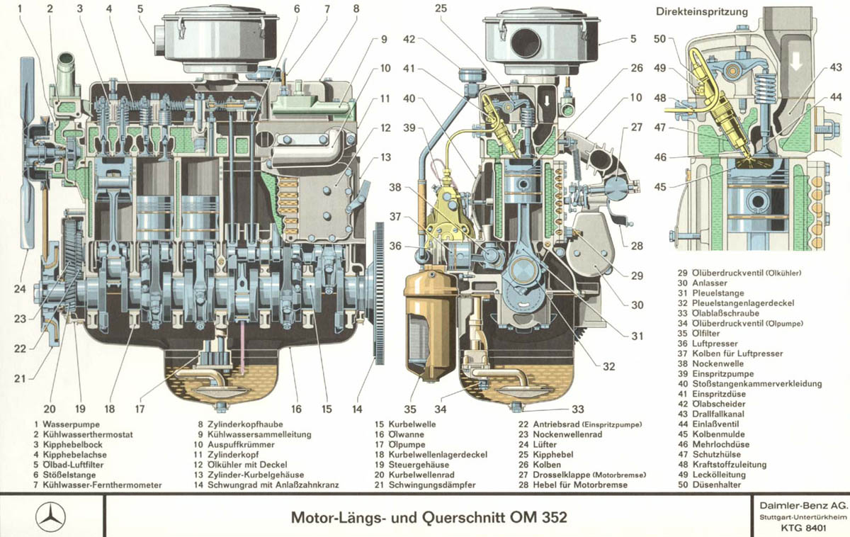
 Cutaway model OM 352 |
|
| Mercedes-Benz OM 352 | |
| Production period: | since 1963 |
| Manufacturer: | Daimler Benz |
| Working principle: | diesel |
| Motor design: | Six-cylinder in-line engine |
| Displacement: | 5675 cm 3 |
| Mixture preparation: | Direct injection |
| Engine charging: | Vacuum cleaner or with turbocharger |
| Power: | 48-127 kW |
| Previous model: | OM 322 |
| Successor: | OM 366 |
The Mercedes-Benz OM 352 is an in-line six-cylinder diesel engine (OM = oil engine) with direct injection from Daimler-Benz AG , which was produced in series from 1963 at the Mercedes-Benz plant in Mannheim and from 1970 onwards by various licensees. It was presented in 1964 at the Geneva Motor Show . From 1966, the engine was also available as the OM 352 A with an exhaust gas turbocharger . Later there were also multi-fuel variants and turbocharged models with intercoolers . For NATO also has foreign detonator (M 352) offered. Due to the wide variety of models in the OM 352 series, some engines are also referred to as OM 353 and OM 344. The engine was mainly used in medium-duty commercial vehicles of the Mercedes-Benz brand , but was also used in machines and vehicles of other brands. He is considered very reliable and has great reserves of strength. The OM 352 belongs to the small OM 300 model family and replaced the pre-chamber machines of the OM 322 series. It was manufactured for the German market for around 30 years. The introduction of new emissions regulations at the beginning of the 1990s meant the end of the OM 352, whose development potential was largely exhausted at that time. At the end of the 1970s, it was one of the most widespread truck engines in Germany, with more than 300,000 copies made.
Development and availability
Development of the OM 352 began in the early 1950s as the successor to engines with pre-chamber injection . The pre-chamber engines of the OM 302 series had been developed in the 1940s, but were not used due to the war; only the successor series OM 312 was produced in series. In order to further increase the performance, the engines were drilled out and provided with new pre-chambers, but the new engines of the OM 322 series did not prove to be stable because the pre-chambers had reached the limit of thermal load capacity. The development of an engine with direct injection had the highest priority at Daimler-Benz as early as 1956. For this purpose, Daimler-Benz hired Alfred Müller-Berner, who was employed at Leyland, to manage the development. After various tests, the engine was finally built with swirl inlet ports, a central four-jet injection nozzle and a cylindrical combustion chamber in the piston. When the engine was ready for series production, there were initially bottlenecks in engine production, so that in 1963 only a small number of engines were produced, which primarily went to truck production in Wörth. The engine was only available in sufficient numbers from the summer of 1964. The 1966 offered supercharged engines have loaders from Eberspächer , Garrett or Kuhnle, Kopp & Kausch .
technology
The OM 352 is an in- line six - cylinder four - stroke diesel engine with direct injection , pressure circulating lubrication , OHV valve control and water cooling . Its displacement is 5675 cm³. In a cylinder bore of 97 mm and a piston stroke mm 128 of the engine is as long Huber designed that its rated power at 2800 min -1 achieved. The power spectrum ranges from 48 kW as a naturally aspirated engine ( Unimog 406 ) to 127 kW as a supercharger engine; the engines designated as OM 362 LA with an additional charge air cooler achieve an output of 141 kW.
Crankcase
The crankcase of the OM 352 is made of a gray cast alloy and consists of two parts, the lower crankshaft housing part with the oil pan and the upper part with the cylinder bank and the camshaft . The cylinders have no liners. The upper and lower parts of the crankcase are connected to one another at the level of the horizontal center of the crankshaft. On the power delivery side, the housing for the clutch is flanged on at the point of the flywheel . Various components such as the oil filter housing, alternator and starter are screwed onto the outside of the crankcase.
Piston and crank mechanism
The pistons were supplied by Mahle and are forged from light metal . They have three compression rings and two oil control rings and transfer the power to the crankshaft via diagonally split connecting rods made of heat-treated steel . The material of the connecting rod bearing shells is lead bronze , they are set in a steel support shell. The crankshaft is also made of heat-treated steel and forged, it has seven bearings, the bearing shells are made of lead bronze like those of the connecting rods. The crankshaft webs are provided with counterweights, and a vibration damper is attached behind the crankshaft gear that drives the camshaft.
Cylinder head

The OM 352 has one cylinder head for all six cylinders, which is made from a molybdenum - chromium- cast iron alloy. The cylinder head gasket is made of asbestos . The cylinder head is essentially divided into two parts, the valve train side and the intake pipe , which is not flanged to the cylinder head but is designed as part of the cylinder head. This design already existed in the Daimler-Benz pre-chamber engines. A total of six swirl channels, arranged in pairs, lead from the intake pipe to the inlet valves, next to which the outlet valves are located. The two inner cylinder pairs each share an exhaust port, while the outer cylinders each have their own exhaust port (see picture on the right), they open below the intake pipe in the exhaust manifold , which is a quadruple manifold . If you look at the engine from the front, the rocker arms and injection nozzles are to the left of the intake pipe. The four-hole injection nozzles are located inside the cylinder head and are inclined at an angle of 30 ° to the combustion chamber. The bumpers for the valve train, which are common in an OHV engine , are routed through the cylinder head on the OM 352 opposite the exhaust side. The cooling jacket is drawn around the cylinders, between the exhaust ports and around the lower part of the injectors and valves.
Externally, the cylinder heads of the OM 352 and OM 352 A differ in the position of the air intake port and the design of the exhaust manifold. In the naturally aspirated engines, the air filter box is mounted in the middle of the cylinder head, while the four-flow exhaust manifold leads downwards. In the Unimog 406 , an additional cyclone filter could be supplied on request for the naturally aspirated engine. The supercharger engines have an air intake port that is led to the front or back and to which the exhaust gas turbocharger is directly attached because the engine does not have a charge air cooler. Here, too, the exhaust manifold has four branches, but it is led upwards so that the exhaust gas flow can drive the turbine wheel of the turbocharger. The exhaust gas is routed from the turbocharger down through a flange manifold to the exhaust. The exhaust gas turbocharger is connected to the lubrication system with a separate oil pressure line; the hot oil runs from the charger back to the oil cooler via a second pressure line. A collecting line for the engine's cooling water runs between the exhaust manifold and the cylinder head cover, which opens out on the front of the engine and is connected there to the tubular cooler. At the end of the exhaust manifold directly in front of the turbocharger, a throttle valve is installed that is used as an engine brake. The engine is also switched off via this device.
Valve train and engine control

The camshaft in the crankcase has four bearings and is made of hardened heat-treated steel. It is flange-shaped on its front side in order to accommodate the helical drive wheel. Another gear is mounted between the flange and the drive wheel, which drives the injection pump. In the middle of the camshaft is a drive wheel for the engine's oil pump. The valves hanging in the cylinder head, one inlet and one outlet valve of the same size for each cylinder, are actuated by the camshaft via push rods and rocker arms, the engine does not have valve seat inserts. The rocker arms are mounted in pairs on a total of six rocker arm brackets and are pressed against the brackets with springs on the rocker arm axis. The fuel is delivered to the four-hole injection nozzles by a Bosch in-line injection pump, which is driven by the camshaft via the aforementioned gear. The engine has a felt tube fuel filter.
Lubrication and ancillary equipment
The oil pump is placed in the middle of the engine in the oil pan. It has a short suction pipe with a suction funnel and strainer to suck the oil out of the oil pan and then feed it through the main flow filter to the main oil line. There is also a bypass filter; The main oil filter hangs outside the oil pan behind the oil pump. An oil separator hangs at the top of the cylinder head and is connected to the crankcase by a fixed pipe. The engine also has an oil cooler that is flanged to the crankcase below the exhaust manifold. It is washed around by the engine's cooling water. The water centrifugal pump is built into the cylinder head at the front of the engine and, like the alternator , is driven by a V-belt. The fan wheel is mounted on the shaft of the water pump. The engine has a cooling water thermostat and a remote thermometer. Depending on the purpose of the engine, it is designed for a 12-volt or 24-volt electrical system. A 12-volt alternator with an output of 0.24 kW and a 12-volt armature starter with an output of 3 kW are installed in the 12-volt electrical system ; The same type of 12-volt thrust armature starter is installed in the 24-volt on-board network, but a more powerful 24-volt three-phase alternator with an output of 1.5 kW that begins to charge as soon as the crankshaft starts to turn. However, some models have a 24-volt starter with an output of 4 kW. The motor has an air compressor as a further auxiliary unit .
Motor power levels
| Power level | 48 kW | 50 kW | 59 kW | 62 kW | 66 kW | 74 kW | 81 kW | 92 kW | 93 kW | 96 kW | 110 kW | 115 kW | 124 kW | 127 kW |
|---|---|---|---|---|---|---|---|---|---|---|---|---|---|---|
| Model | OM 352.919 | OM 352.902 | OM 353.902 | OM 353.902 | OM 352.xxx | OM 352.xxx | OM 353.901 | OM 352.xxx | OM 352.xxx | OM 353.961 | OM 352.xxx | OM 352.xxx | OM 352.xxx | OM 352.xxx |
| Exhaust gas turbocharger | No | No | No | No | No | No | No | No | No | No | Yes | Yes | Yes | Yes |
| year | 1964 | 1966 | 1969 | 1971 | 1965 | 1969 | 1969 | 1970 | 1963 | 19xx | 196x | 1966 | 1979 | 19xx |
| Source |
Technical specifications
| model | OM 352 | OM 352 | OM 352 A | OM 353 | OM 352 A |
|---|---|---|---|---|---|
| year | 1964 | 1966 | 1975 | 1975 | 1979 |
| vehicle | Unimog 406 | Mercedes-Benz L 1113 | Unimog 425 | Unimog 435 | Mercedes-Benz LAF 1113 |
| Model | 352.919 | 353.961 | |||
| design type | Inline six-cylinder | ||||
| Working principle | diesel | ||||
| Valve control | OHV, two valves per cylinder | ||||
| Charging | - | Exhaust gas turbocharger without charge air cooler | - | Exhaust gas turbocharger without charge air cooler | |
| Engine lubrication | Pressure circulation (wet sump) | ||||
| Mixture formation | Direct injection | ||||
| Injection pump | Bosch PES6A80C410R52085 | ||||
| Bore × stroke | 97 mm × 128 mm | ||||
| Displacement | 5675 cm 3 | ||||
| rated capacity | 48 kW at 2550 min -1 | 93 kW at 2800 min -1 | 110 kW at 2550 min -1 | 96 kW at 2800 min -1 | 124 kW at 2800 min -1 |
| maximum torque | 232 Nm at xxxx min −1 | 353 N · m at 1600 min -1 | 461 N · m at 1600 min -1 | 363 N · m at 1700 min -1 | xxx Nm at xxxx min −1 |
| Idle speed | xxx min −1 | xxx min −1 | xxx min −1 | 700 min -1 | xxx min −1 |
| Medium work pressure | 784.5 kPa | ||||
| Medium piston speed | 11.95 m / s | ||||
| Crank ratio | 3.59 | ||||
| Injection pressure | 19.6 MPa | 19.6 MPa | |||
| Compression ratio | 17: 1 | 16: 1 | 17: 1 | ||
| Compression at engine start | 2.2 - 2.4 MPa not less than 2 MPa |
||||
| Dimensions | 410 kg | 460 kg | 460 kg | ||
| Firing order | 1-5-3-6-2-4 | ||||
| Sump capacity | 7–9 l | ||||
| Water cooler capacity | 24 l | ||||
| Valve clearance (cold) [inlet / outlet] | 0.2mm / 0.3mm | 0.4mm / 0.6mm | 0.2mm / 0.3mm | 0.4mm / 0.6mm | |
| Inlet valve opening | 29 ° before TDC | 18 ° before TDC | |||
| Closing the inlet valve | 55.9 ° after UT | ||||
| Opening exhaust valve | 54 ° before UT | ||||
| Closing the exhaust valve | 20.8 ° after TDC | ||||
| Start of delivery of injection pump | 23 + 8 ° before TDC | ||||
| alternator | 12 V, 0.24 kW | ||||
| source | |||||
literature
- Mercedes-Benz do Brasil SA (Ed.): Manual de Instruçōes - Motores Industriais OM-314 OM-352 OM-352A OM-355/5 OM-355 (= operating instructions Mercedes-Benz OM 352 ). September 1987.
Web links
- Sectional drawings of the engine , accessed February 8, 2018.
Remarks
-
↑ The engine was installed 35,303 times in the Unimog 406 (37,069 BR 406 vehicles in total, 1766 of which were not with OM 352), cf. Vogler pp. 34 and 85;
The engine was only installed in the Unimog 416, 45,544 of these vehicles were built, cf. Vogler p. 104;
The Unimog 435 equipped with OM 352 was built 30,726 times, cf. Daimler: 435 series ;
The Unimog 425 was built 3135 times, cf. Daimler: Series 425
The Unimog 419 also received only the OM 352, 2416 vehicles were built, cf. Vogler p. 116 ff;
Of the Unimog 426, 2,643 units with OM 352 were built, cf. Vogler p. 122
180,000 OM 352s were produced under license in Iran, cf. Daimler birth of a legend: the 300 engine series presented in 1949 is a big hit
Individual evidence
- ↑ a b c d e f Carl-Heinz Vogler: Unimog 406 - Type history and technology. Geramond, Munich 2016, ISBN 978-3-86245-576-8 . P. 34.
- ↑ a b Daimler AG (ed.): Diesel engines in Mercedes-Benz commercial vehicles . Retrieved February 4, 2018.
- ↑ a b c d e f g h i j k Daimler AG (ed.): Birth of a legend: The 300 engine series presented in 1949 is a big hit . April 22, 2009. Retrieved February 4, 2018.
- ↑ Manual de Instruçōes. P. 42 ff.
- ↑ Carl-Heinz Vogler: Unimog 406 - Type history and technology. Geramond, Munich 2016, ISBN 978-3-86245-576-8 . P. 35.
- ↑ a b c Harald Maass: Design and main dimensions of the internal combustion engine. In: Hans List (Ed.): The internal combustion engine - new series. Volume 1, Springer, Vienna / New York, 1979, ISBN 3-211-81562-7 , urn : nbn: de: 1111-201201265484 , p. 250.
- ↑ Olaf von Fersen (Ed.): A Century of Automobile Technology: Commercial Vehicles , Springer, Heidelberg 1987, ISBN 978-3-662-01120-1 , p. 136
- ↑ a b c d e f g h i j k Association of the Automotive Industry: Daimler-Benz AG. Type L 1113 LK 1113 ( Memento of the original dated February 8, 2018 in the Internet Archive ) Info: The archive link was inserted automatically and has not yet been checked. Please check the original and archive link according to the instructions and then remove this notice. Group 14, December 1966. DK 629.113.5
- ↑ a b c d e f g h Daimler AG (ed.): OM 352 A - longitudinal u. Cross-section. KTG 8941. Retrieved February 5, 2018.
- ↑ a b Daimler AG (Ed.): Sectional view of cylinder head OM 352 . Retrieved February 6, 2018.
- ↑ a b c Daimler AG (Ed.): Sectional view of cylinder head OM 352 . Retrieved February 6, 2018
- ↑ H. Kremser: The structure of high-speed internal combustion engines for motor vehicles and railcars . In: Hans List (Ed.): The internal combustion engine . tape 11 . Springer, Vienna 1942, ISBN 978-3-7091-5016-0 , p. 76 , doi : 10.1007 / 978-3-7091-5016-0 ( limited preview in Google book search).
- ↑ Daimler AG (Ed.): Pre-Chamber Adieu: In 1964, the first direct injection engines appear in trucks and buses . February 12, 2009, accessed February 5, 2018.
- ↑ a b c d Daimler AG (Ed.): OM 352 - longitudinal u. Cross-section. KTG 8401. Retrieved February 5, 2018.
- ↑ Carl-Heinz Vogler: Unimog 406 - Type history and technology. Geramond, Munich 2016, ISBN 978-3-86245-576-8 . P. 48.
- ^ A b Association of the Automotive Industry: Daimler-Benz AG. Type O 302 ( Memento of the original dated February 8, 2018 in the Internet Archive ) Info: The archive link was inserted automatically and has not yet been checked. Please check the original and archive link according to the instructions and then remove this notice. Group 16, June 1965. DK 629.113.5.
- ↑ a b Manual de Instruçōes. P. 40.
- ↑ a b Carl-Heinz Vogler: Unimog 406 - Type history and technology. Geramond, Munich 2016, ISBN 978-3-86245-576-8 . P. 61.
- ↑ Carl-Heinz Vogler: Unimog 406 - Type history and technology. Geramond, Munich 2016, ISBN 978-3-86245-576-8 . P. 71.
- ↑ Carl-Heinz Vogler: Unimog 406 - Type history and technology. Geramond, Munich 2016, ISBN 978-3-86245-576-8 . P. 76.
- ↑ Carl-Heinz Vogler: Unimog 406 - Type history and technology. Geramond, Munich 2016, ISBN 978-3-86245-576-8 . P. 80.
- ↑ a b Carl-Heinz Vogler: Unimog 406 - Type history and technology. Geramond, Munich 2016, ISBN 978-3-86245-576-8 . P. 104.
- ↑ Carl-Heinz Vogler: Unimog 406 - Type history and technology. Geramond, Munich 2016, ISBN 978-3-86245-576-8 . P. 102.
- ↑ Carl-Heinz Vogler: Unimog 406 - Type history and technology. Geramond, Munich 2016, ISBN 978-3-86245-576-8 . P. 106.
- ↑ a b AG Daimler-Benz (ed.): Unimog 435 workshop manual (= Workshop Manual Unimog 435), Book 1 Section 1.2 / 1.
- ↑ a b Federal Office for Civil Protection and Disaster Relief: Hose Trolley SW 2000-Tr , LAF 1113 B / 36
- ↑ Manual de Instruçōes. P. 39.
- ↑ Vintage tractor. Issue 11–12 / 2012.
- ↑ Federal Office for Civil Protection and Disaster Assistance : Data sheet for the rescue vehicle RW1 , Unimog U 1300 L