Network (electrical engineering)
In theoretical electrical engineering , a network is understood to mean differently complex mathematical models of an electrical circuit , or parts of such a circuit, which are used for modeling within the framework of system theory such as circuit analysis and circuit synthesis.
General
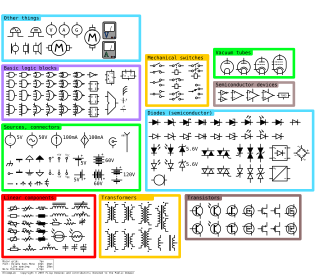
The graphic representation of electrical components takes place in the form of circuit diagrams in an abstract way. If, in the context of modeling, electrical circuits are reduced to their essential components and parameters for easier investigation, one speaks of an equivalent circuit . The extent of the reduction is determined by the respective application, taking into account that the error in the modeling must not become too large.
If the relationships between the voltages and currents occurring in a network are linear, one speaks of linear (electrical) networks. The time-invariant networks, also referred to as linear time-invariant systems , allow a further simplification . In this case, the parameters are not subject to any time dependency; among other things, the superposition theorem applies . This means that further systematic methods can be used for analysis, such as the mesh current method and the node potential method .
Examples of different types of simple networks include resistor networks , voltage and current dividers or networks in the form of different types of filter topologies , electrical lines . If the specific internal structure of a network is not of interest, but only the behavior at its connections to the outside, the connections are also referred to as gateways in this context , the description is based on the behavior at these connections. The so - called two - port is an important form of description .
Models
There are different network models depending on the requirements. In the following, the two models, with concentrated components and with distributed components, are shown.
Network model with concentrated elements
The network model with concentrated elements, English lumped element model , describes electrical circuits with individual elements in which the determining parameters are concentrated. The connecting lines are assumed to be ideal, i.e. without losses or any other influence. Field variables such as electrical or magnetic flux density do not occur directly. The physical properties of the network are approximated by the properties and parameters in the individual components, which simplifies the model description of this network model and is used, among other things, within the framework of Kirchhoff's rules ( e.g. mesh rule and knot rule ). Examples of lumped elements include ideal resistors , capacitors , coils, and voltage and current sources .
In mathematical terms, this simplification allows the state space representation to be reduced to a finite number of parameters. The partial differential equations are transferred to ordinary differential equations with a finite number of parameters.
The approximation of the validity of this model and the simplification is given if the condition
is satisfied. describes the characteristic spatial expansion of the network, the wavelengths occurring in the network . Another possibility to check the validity of the model is to consider the signal propagation times within the network: If these signal propagation times can be neglected in an application, the network model can be used with concentrated elements.
If the characteristic spatial expansion of the network comes in the order of magnitude of the wavelength occurring in it , the transition is fluid and characterized by increasing errors in the model, the network model with distributed elements must be switched over.
Network model with distributed elements
The network model with distributed elements, english distributed element model , or as a transmission line model referred to, describes electrical circuits in infinitesimally small and spatially quasi "smeared" components in the form of pipe linings . The deposits that occur are the resistance layer R ', the capacitance layer C', the inductance layer L 'and the dissipation layer G'. The connecting lines within the network are also modeled from these spatially distributed surfaces and lines are no longer assumed to be ideal. In contrast to the simpler network model with concentrated elements, the methods based on the simplification, such as Kirchhoff's rules, can no longer be used; instead, the system description is based on partial differential equations. A graphic representation in circuit diagrams with concentrated components is generally no longer possible.
This model is used, among other things, in line theory, as it is expressed, among other things, in the context of the telegraph equation . The use of this network model can also be necessary for small spatial structures with the characteristic extent if the wavelengths occurring are approximately of the same order of magnitude or less. This case is synonymous with the occurrence of high frequencies . For this reason, the network model with distributed elements is used in the field of high-frequency technology , such as the modeling of striplines .
context
In addition to the various network models, the physical relationships in electrical networks can also be described with the help of field theory , based on Maxwell's equations and material equations of electrodynamics and with field variables such as the electric field or the magnetic flux density . The partial differential equations that arise can usually no longer be solved analytically, apart from a few problems. Numerical solution methods such as the finite element method are used.
literature
- Karl Küpfmüller, Wolfgang Mathis, Albrecht Reibiger: Theoretical electrical engineering and electronics . 18th edition. Springer, 2008, ISBN 978-3-540-78589-7 , 4th chapter.


