
Beet harvester
A beet harvester is an agricultural machine for harvesting of sugar beets . While the first machines were pulled by a tractor and could only lift one row, modern self-propelled beet harvesters mostly have 6-row lifting devices. The beets are lifted out of the earth by lifting shares. The beets are separated from the adhering earth by cleaning rollers and sieve belts and transported to the machine's storage bunker. The beets are on the sidelines in rent saved or overloaded during Rodens onto a transport vehicle. The leaves of the beets are removed. They remain on the field for fertilization or serve as fodder for cattle and can be fed fresh or as silage .


Work steps
- Remove leaves from the beet (flail)
- Remove leaf stems
- Pulling (clearing) the whole turnip out of the earth
- Clean the beet from sticking earth
- Transport of beets to the edge of the field and to the rent or
- Overloaded onto a means of transport
Harvesting process
Deductible ("2-phase") procedure
- 2-phase process
1st part,
front attachment: leaf
flail rear attachment: harvester
2nd part,
self-propelled beet collecting bunker
.JPG)

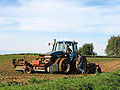
In the settling or two-phase process, the beets are harvested in two operations. First the leaves are cut off and in some systems the beets are pulled out of the ground and deposited at the same time. This work step is primarily carried out by implements attached to tractors. It is driven by the tractor's front or rear PTO shaft . In the case of pushed systems, the reversing tractor equipped with a reversing device drives over soil that has already been completely harvested. More common are systems in which a haulm topper is attached to the front of the tractor and a lifting unit is attached to the rear. Since the tractor drives through the rows of beets that have not yet been cleared, it is equipped with thinner, so-called maintenance tires in this case. These tires are so narrow that they can drive through the rows without damaging the beets. Then a so-called loading bunker collects the deposited beets, thereby removing coarse dirt deposits. After cleaning, the beets remain in the bunker until it is full. The harvested crop is emptied either onto a pile or onto a trailer via a conveyor belt . In addition to towed systems, there are also loading bunkers that are self-propelled (an independent machine, i.e. without an external drive). Weaning systems have largely been replaced by self-propelled harvesters in Germany. In other sugar beet growing countries, particularly in Belgium, the “2-phase” system is the most common harvesting method for sugar beet.
Harvester
With the full harvester, all operations necessary for harvesting are carried out. This means that the topping, lifting and cleaning of the beets as well as emptying the bunker is done by one machine. There are also towed and self-propelled machines for this harvesting method. The machines pulled by a tractor are even more common, but are increasingly being replaced by self-propelled vehicles. Systems that harvest up to 3 rows at the same time are common in Germany, but there are e.g. B. in the USA also drawn 12-line herons.

With modern self-propelled full harvesters, 6 rows are usually harvested at the same time. Lately there are also 9- or 12-row harvesters, but these are more intended for locations with large pitch lengths or sizes. Like current combine harvesters , these machines have a removable lifting device. In Germany, these systems are rarely used because of their excessive width and length, with the lifting unit attached to the rear.
Self-propelled 6-row beet harvesters work around 74% of the cultivation area in Germany. 1-row harvesters only harvest less than 4%, and 2-row harvesters bring in around 9% of the sugar beet crops. The rest is distributed among other systems.
Assemblies
Schlegler

Example of a rotating flail shaft

... and at a standstill


The beet leaf is removed with the topper (also called a chopper). It consists of a topper shaft rotating transversely to the direction of travel and the associated topper housing. The flail knives, mostly made of bent flat iron, are mounted on the flail shaft in a pendulum manner in the direction of travel.
The cut leaves are thrown up in the topper housing, caught in a trough, conveyed to the side (e.g. by a leaf auger) and distributed there by a leaf spinner away from the beet crop. This design is called leaf flail.
In another version, the leaf is cut very finely by special knives and placed between the beet rows by means of guide and baffle plates. It should stay there and not affect the further lifting process. The technical term for this is: Integral Schlegler.
The coupling of both types is also used. The structure is like a normal leaf flail, only there are additional guide plates, as with the integral flail, and a flap to close the leaf auger trough. When the flap is open, it is a leaf flail with side ejection; when the flap is closed, the leaf is thrown between the rows.
Decapper
Removing the beet heads is the job of the topper. The re-topper, sometimes just called "topper", is again available in several designs. What they all have in common are the height-adjustable scalping knives, which are mounted at an angle to the direction of travel and are spring-loaded. The knife shapes (e.g. sickle knife) and the angle of attack are different. Guide springs are arranged behind the knives. They ensure that the cut beet heads are guided between the rows. Sometimes grinding combs and sometimes wheels are used for height guidance. In addition to the height adjustment, there is usually a device for adjusting the slice thickness. The Exaktköpfer is a special design. Its serrated, driven jockey wheels ensure particularly precise scalping.
Defoliator

Leaf removers are used to get even more yield from the sugar beet. These can complement or completely replace the decopper. This technique tries to remove leaves and stems from the beet without leaving any residue. A second shaft with rubber or plastic flails is arranged behind the flail shaft. With the first wave, the leaves of the beets are cut higher than when using a topper. The rubbers of the second shaft "rub" on the beet head without damaging it significantly. The beet quality that can be achieved depends largely on the nature of the material and the wear and tear on the rubber flails. Equally important is an even crop of beets. If the beets are at different heights from the ground or if there is a large difference in size in the crop, leaf remnants can remain on the smaller sugar beets.
The operation of an additional defoliator shaft requires a higher drive power. This is due to more frictional losses in the bearing and drive of the leaf-removing shaft, the sliding friction of the rubber flails on the beets and the additional air resistance of the rubber flails.
Lifting shares
Lifting share 3D

Wheel harvester 3D


In the past, the tine share and the plate share were common types of lifting shares. Today the sugar beets are lifted out of the ground either by polder shares or wheel lift shares.
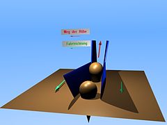
Polder shares, also known as vibrating or wing shares, are wing-shaped plates arranged in pairs. These are moved up and down simultaneously or in different phases. The pair of shares is arranged in an oblique V-shape, so to speak, with the tip pointing back and down. The beet is pushed upwards by the forward movement. The shaking should enable gentle clearing, while at the same time soil and leaves are prevented from sticking. The vibrating shares are driven by push rods on an eccentric shaft. A linear guide ensures that the vibrating shares can follow the row of beets to the side in a limited area.
Wheel shares, sometimes called Oppel wheels , are V-shaped wheels arranged in pairs. At least one of them is powered. During the rotation, the sugar beet is pinched and pulled out. Here, too, a suitable bearing ensures that the wheels can move sideways. A rigid coulter is sometimes used instead of the second wheel.
The coulters can reach different depths into the soil by means of a height adjustment and are guided parallel to the ground with a depth guide. (See Sections 3.9.2 and 4. ) Since 2009 there have been lifting units with individually height-adjustable vibrating shares for the first time. This even enables the height difference between individual rows (lanes or furrows) to be compensated.
cleaning

The cleaning process gently removes earth residues from the sugar beet. The beets often go through several stages of cleaning. The lifting shares pass to the first stage. This often consists of pick-up rollers or so-called lifting rollers rotating in the direction of travel. In the most popular designs, several of these rollers are operated in series. Our first mostly all Rodewalzen with spiral are round steel - coils fitted. Like an Archimedean screw , the beets are conveyed to the center of the lifting unit and through the direction of rotation backwards to the second stage. Some manufacturers put at the first stage instead Rodewalzen screen stars or so-called recording stars. The most important tasks of the first stage are sifting out coarse dirt and merging the beets into a stream. In most systems, this beet flow is directed through between the front wheels. With the 9 or 12-row harvester, this becomes a limiting factor because the passage and thus the efficiency is limited. The execution of the next stage of the main cleaning depends on the size of the beet harvester. The following systems are used individually or in combination:
- Sieve stars
- Nub rollers
- Pinch rollers
- Sieve belts (also called sieve chain)
With an elevator belt , the last stage, the sugar beets are continuously conveyed upwards and thrown into the bunker .
bunker
The storage bunker holds the harvested sugar beets. A large worm shaft ensures even distribution in the bunker. Horizontal conveyors on the floor of the bunker are scraper floors . These are paired chain strands that are connected several times by steel profiles. If the chains are pulled across the ground, the beets start moving.
With older systems, the beets are unloaded simply by tipping them. In order to enable overloading on trailers, it is preferable to use a sieve belt on a folding frame. This unloading belt is supplied with beets through the scraper floors in the bunker. The height of the unloading belt can be varied so that the sugar beet can either be placed on a pile or loaded onto a transport vehicle.

Beet harvester when bunking

Pulled harvester unloading
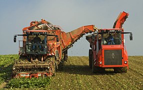
Harvester loading onto a Holmer system vehicle with beet bunker

Sugar beet rent


landing gear

The remote harvesters and trailed harvesters are simple, single-axle machines. All assemblies are driven by the pulling tractor via PTO shaft or hydraulics. Self-propelled beet harvesters are always designed with more than one axle. Large, wide wheels are used, often in odd numbers. The unpaired wheel runs between the tracks of the other wheels. The purpose of this construction is to reduce the pressure on the ground and to roll over the loose dirt that has been removed from the beets. For the larger working widths of the 9- and 12-row machines, telescopic axles are used to enlarge the area covered. Instead of an unpaired bike, other makes have the option of bending the frame. With the articulated frame and all-wheel steering, the beet harvester can roll over the field at an angle in the so-called crab or gentle gear.
The axles are connected to the frame without suspension. At least one axle is mounted oscillating about the vehicle's longitudinal axis in order to enable the axles to be crossed. If there are more than two axes, these must also allow height compensation. The harvesters are driven diesel-hydraulically . A diesel engine drives several hydraulic pumps. Hydraulic motors sometimes transmit the power directly, but primarily through gears, to the drive wheels. The steering is also operated hydraulically.
engine
Diesel engines are predominantly used in beet harvesters . Units are taken over from the shelves of commercial vehicle manufacturers unchanged or slightly modified. The motors are adapted to the power requirements of the different machines. Six-row self-propelled engines have engines with outputs between around 380 and 600 hp. Political pressure for economical and clean drives is causing more and more manufacturers to use electronically controlled motors. This CAN bus control allows the engine speed and the power provided to be adapted to the actual drive power. This means that the lowest possible speed is always cleared to save costs. This type of motor control is known as automotive control. Another advantage of electronic engine management is the ability to diagnose errors "on board".
A trend that is becoming increasingly evident is the use of bio-fuels such as biodiesel or rapeseed oil . While operation with bio-diesel is approved by most manufacturers and is unproblematic, there are some difficulties when using pure rapeseed oil. For example, for operation with rapeseed oil, the engine must be equipped with a fuel heater, other filters and possibly an additional tank. In addition, the oil change intervals are shortened in order to prevent the rapeseed oil from entering the engine oil too much. Failure to comply could result in engine damage.
Aid and support systems
Monitoring and regulation

Electronic and optical systems are used in modern beet harvesters to monitor the lifting process. The machines are electronically monitored with a large number of sensors and potentiometers. z. B. Hall sensors, pressure, speed and temperature sensors. The data recorded in this way are processed by the machine's control units and at the same time displayed to the driver via a data terminal . The terminal not only shows the position of relevant assemblies (e.g. lifting share height) and the chassis (e.g. with all-wheel steering), but settings can also be made. The use of more and more sensors and control devices enables manufacturers to implement automatic controls such as depth control of the lifting unit or speed adjustment of the screening stars. For example, the following control devices are installed in a HOLMER Terra Dos T4:
- 5 computers for machine control
- 1 travel drive control unit
- 1 Level compensation control unit for 2nd rear axle
- 2 computers for harvesters and toppers
- 1 vehicle management computer
- 1 engine control unit (diesel engine)
Certain areas of the machine have to be monitored optically with cameras. This includes the rear view when reversing and the cleaning process during the lifting operation. With one or more video monitors in the cab, the driver always has everything in view. Dangers and problems can be recognized in good time and the machine set correctly.
Automatic row guidance
While the beet rows were followed by hand in older systems, this is done by a parallel driving device in modern beet harvesters . The beets (using lifting shares) and the leaves (using leaf sensors) are scanned. The movements are converted into electrical signals by potentiometers . The electronics use it to control the hydraulic steering.
Depth guidance
In order to be able to clear clear, the coulters must always have a certain height to the ground. This is ensured by the depth guidance. The profile of the floor is scanned using grinding skids or feeler wheels. The lifting and lowering of the lifting unit is controlled hydraulically or electronically. The two sides are regulated independently of each other. With particularly wide lifting units (e.g. 9-row units) it becomes more difficult to maintain continuous contact with the ground (lanes, bumps in the direction of travel). To prevent this, the units are shared by some manufacturers.
Slope compensation
So-called slope disks are used on trailed beet harvesters in order to stay in lane on a transverse slope . This is a rotating steel disc that is hydraulically pressed into the ground behind the lifter. Like a boat with a keel, this prevents drifting. Counter-steering with the steering is also a method of avoiding drifting on a slope. The latter method is achieved by steering the rear axle (s) for self-propelled vehicles and by swiveling a wheel for pulled harvesters. It is the driver's responsibility to steer against the slope, depending on the ground conditions and slope.
Slope support
Due to their high structure, the center of gravity of full beet harvesters (especially fully loaded self-propelled) is unfavorably high. In order to enable clearing on the slope, the pivoting axles are supported with hydraulic cylinders.
Adjustment of the beet harvester
Harvest losses occur due to incorrect heading, breaking off of beet parts or due to the beets not grasped by the lifting unit. A beet harvester must therefore be adjusted depending on the beet population and the soil conditions.
- The flail should separate the beet leaves 1–3 cm above the beet body. Ideally, the sugar beet is decapitated directly below the leaf base. Just 1 cm more means a harvest mass loss of 7 to 9%.
- The lifting shares may only be led as deep as necessary. Deep lifting conveys an unnecessary amount of soil into the harvester and has to be cleaned up again. If, on the other hand, the beet is cleared too shallowly, the tips of the beet remain in the ground or the coulters cut the beets. If the soil is loose, the beets can tip over and are no longer caught.
- The lifting speed is to be adjusted depending on the throughput and cleaning ability of the harvester as well as the quality of the lifted beets.
- During cleaning, beet damage and root breakage are avoided by the low speed of the sieve units. The speeds are to be selected so low that perfect further transport is just possible. In order to remove more adhering earth, however, higher speeds should be aimed for. This setting is also dependent on the beet and the nature of the soil. The best compromise is reached by trying.
Procedure for clearing
The procedure for clearing a beet field is shown below. It is important whether it is a pulled or a pushed harvester (lifting unit in front of the first axle), or whether the system used picks up the beets on both sides or only on one side. The beet field is enclosed by the headland . This has already been measured when drilling on the harvester used and normally comprises between 24 and 48 beet rows.
In the case of harvesting, it is not the track lying at the edge of the field that is cleared first, but the second or third tramline first, so that all beets can be picked up at the edge with one-sided clearing systems. This procedure is sometimes unnecessary with systems that are grubbed up or pushed on both sides. Sliding and bilateral systems have a clear advantage when it comes to anroding, as there is no need to drive over the beet crop and therefore there are no losses in this regard. In the headland, an area is cleared initially in order to unload the harvested beets. If necessary, if there is insufficient space or the bunker volume is too small, the first beets can be loaded onto a trailer.
Harvesters harvesting one side only dig once or several times through the middle of the field and back on the outside of the field to expose the headland there as well. Now it is driven alternately around the beds created in this way . This prevents beets from being driven over again. Depending on the size and shape of the field, several beds are carved out. Beet harvesters working on both sides, on the other hand, can dig up and down the rows as desired after clearing the headland. In long fields, dividing into beds is also common. In this way, the farmer avoids long empty journeys between the beet crop and the edge of the field by creating separate heaps. In this context, beets are also loaded onto removal vehicles (e.g. tractors with trailers). You save the beet harvesters having to hire them. The pile itself is formed during the bunkering , depending on the later loading process (e.g. beet cleaning loader ).
history
In the early days of sugar beet cultivation, a lot of work was done by hand. The beets were lifted out of the ground with various beet forks, then decapitated by hand and thrown into piles, from where they were transported away in horse carts.
In the course of advancing industrialization in the last century, it became possible to facilitate agricultural work through the use of technology. Until the 1920s, several machines were built that either did the topping or were used for clearing. These were first drawn by horses or oxen.
Otto Wilke , a farmer from Harber in Lower Saxony, had the idea of building a machine to harvest the sugar beet. The beet leaves should be separated exactly, the sugar beets cleared and both be deposited separately on the field. In cooperation with master electrician Heinrich Meisoll and master locksmith Friedrich Bote, Otto Wilke built the first prototype of a beet harvester in 1927. A wheel fitted with tines (hedgehog button) ensured that the height of the beet head could be felt and that the leaf was cut precisely. A beet lifting device, patented in 1928, pulled the beets out of the ground and then laid them in a row on swaths . The rotary motion of the serrated wheels was used to drive the sieve chains and conveyors.
The Krupp company took over the series production and put the first advanced machine up for sale in 1936. At the end of 1936, Lanz took over the continuation of production in Mannheim. With the invention of the power take-off shaft, the work of the beet harvester could be significantly improved by eliminating the failure-prone drive via the wheel.
After the Second World War , the Allies took over the patent and sold it to the Wilhelm Stoll company in Broistedt . This continuously developed the beet harvester. So the bunker for the beets became larger and a flail took over the separation of the leaf, while the decapper was only responsible for the heads of the beets. The cleaning of the beets was refined and the number of rows increased to three.
The TIM company put its first “lift-up sugar beet harvester” up for sale in 1961 and was able to assert itself on the market for some time with its two-row and three-row lifting units. But it was pushed into an outsider role by the growing competition of the six-row lifting units.
At the end of the 1960s, the agricultural machinery mechanic Duquenne from Belgium built a six-row, self-propelled one-man head bunker on the initiative of the Tirlemontoise sugar factory . The sugar factories were already waiting for such innovations to drive forward further rationalization of sugar beet cultivation. In 1971, the Duquenne machines were also used for Südzucker AG in Germany. The construction with the lifting unit between the axles had serious problems in wet weather. The front wheels compacted the soil around the beets so much that they could only be cleared poorly and with a high proportion of soil. Südzucker therefore decided to set up a project team to build a 6-row self-propelled vehicle itself. The team, led by Dr. Hans Irion, consisted of farmers and mechanical engineers and was scientifically supported.
The pioneers in the development of 6-row harvesters were the companies Holmer and Ropa . Hermann Paintner, a young farmer from Bavaria, had built a self-propelled sugar beet harvester from old components and parts as early as 1972. The company of Alfons Holmer from Eggmühl received the order for a small series in 1973. The harvesters became known under the name Holmer, System Paintner .

In 1974, Südzucker AG presented the betaking 3000 head bunker to the public. Series production begins in 1976 and ends in 1977 with the sale of the production license to the Stoll company. Stoll, for a long time the market leader in Germany, continued to trust in its drawn products. A mistake, as it turned out later. When developing the 6-row beet harvesters, Stoll overslept the development and has been pushed out of the market.
In 1986, H. Paintner founded his own company in Sittelsdorf called Ropa. From 1988 the harvesters slowly took on today's basic features. Frame with large wheels for low ground pressure, a voluminous bunker, all-wheel steering and the effective cleaning of the beets ensured the breakthrough on the market. Today, these machines, which are occasionally referred to as head bunkers, are standard and an indispensable part of the sugar beet industry.

Timetable
- 1927: Otto Wilke builds the first whole beet harvester
- 1936: first Krupp company, later Lanz in Mannheim, first series production of a whole beet harvester
- from 1945: Stoll takes over the beet harvester production after purchasing the patent rights
- 1961: Tim Thyregod A / S from Denmark add a beet harvester to their range
- 1971: Use of the Duquenne harvester in Germany
- 1972: Paintner builds a 6-row self-propelled harvester
- from 1974: first series production of a self-propelled 6-row lifting bunker. Type: Holmer, System Paintner
- 1974: Südzucker AG builds the betaking 3000
- 1974: Frans and Richard Vervaet build a harvester with a bunker in Biervliet (Netherlands)
- 1986: H. Paintner founds Ropa Fahrzeug und Maschinenbau GmbH
- 1992: three-axle harvester from Ropa
- 1995: three-axle harvester from Ropa with articulated frame
- 1996: Holmer Terra Dos with articulated frame
- 1996: Electronics find their way into beet harvesting technology
- 1998: Euro Tiger from Ropa
- 2004: The Grimme company builds a harvester with crawler tracks
- 2006: Gilles company (Belgium) builds an eight-row, 2-phase harvesting system
- 2006: Ropa builds 9-row lifting unit with quick coupling
- 2007: Agrifac company builds a 12-row self-propelled sugar beet harvester
- 2007: The Terra Dos T3plus from Holmer is equipped with a telescopic, steerable rear axle
- 2008: The Grimme company builds a so-called "defoliator" based on US machines and a towed transfer harvester with an intermediate bunker (2-phase harvesting technology)
- 2009: Holmer Maschinenbau presents the HR harvester with individually height-adjustable vibrating shares and hydraulic stone protection
- 2012: In July 2012, Holmer delivers the 3,000 sugar beet harvester. In December the prototype of the Terra Dos T4-40, a three-axle harvester, will be tested in the field
Manufacturer
Current and former manufacturers are listed alphabetically here.
- Agrifac Machinery BV ( Netherlands ) - Brands: Agrifac, formerly also Riecam and WKM - in the Exel Industries portfolio since 2012
- DeWulf ( Belgium )
- Ets Franquet SA ( France )
- Gilles SA (Belgium)
- Gomselmash ( Belarus )
- Grimme Landmaschinenfabrik GmbH & Co. KG (Germany)
- Holmer Maschinenbau GmbH (Germany) - in the Exel Industries portfolio since 2013
- MATROT Equipements (France) - in the Exel Industries portfolio since 2001, production until approx. 2012
- Moreau-Agriculture (France) - in the Exel Industries portfolio since 2007, production until approx. 2012
- Ropa Fahrzeug- und Maschinenbau GmbH (Germany)
- Salzkottener Maschinenbau GmbH (Germany) - production until 2012, takeover by the Grimme Group
- Wilhelm Stoll Maschinenfabrik (Germany) - production stopped
- Thyregod A / S ( Denmark )
- Frans Vervaet BV (Netherlands)
Number of machines sold by manufacturer
2012 :
- Grimme 80 pieces (Rexor, Maxtron and Rootster)
- Holmer: 141 pieces (T2 and T3)
- Ropa: 180 pieces
- Vervaet: 28 pieces (Beeteater 26 T and Beeteater 17 T)
Web links
- GDR beet harvesters
- Interesting pictures about agricultural engineering in the years 2001–2007
- Aerial view of a beet harvester during harvest
- Video of a self-propelled beet harvester during the harvest
Individual evidence
- ↑ a b DLG press release No. 34, September 14, 2005.
- ↑ a b Agriculture, specialist level farmer. 7th edition. BLV Verlagsgesellschaft, 2004, ISBN 3-405-16403-6 .
- ↑ a b Food Forum , magazine for employees of the Südzucker Group, issue 53.
- ↑ ropa-maschinenbau.de - History of Hermann Paintner, section 1986 (last accessed on July 4, 2017)
- ↑ a b c d exel-industries.com - Anual Report 2015. P. 4 (timeline), accessed on July 31, 2017 (PDF; 9.66 MB)
- ↑ a b c d manufacturer's own information