
Escapement (clock)

The escapement (formerly also gear ; French échappement ; English escapement ) is the assembly in gear clocks that establishes the connection between the gear train and the regulator (such as the pendulum ). As an anchor escapement , it usually consists of the escapement wheel ( gear wheel , steering wheel or escape wheel ) and the escapement piece ( anchor , rest piece ). The gear regulator brings about the periodic stopping ("inhibiting") of the gear train via the inhibitor engaging in the escape wheel and thus the regular running of the watch. In the opposite direction, he receives energy ( lifting , impulse ) in order not to stop. A pendulum is "lifted" periodically.
This article only describes escapements that are based on classic oscillation systems, i.e. pendulum, balance or foliot (Waag). The conversion of vibrations from other oscillators such as tuning forks , quartz crystals or vibratory silicon elements into the clocked movement of a clockwork is not considered here.
English watchmakers invented three methods of escapement between around 1685 and 1720. In China, an lever escapement was already found in an astronomical clock by Su Song (from 1086).
Types
About 250 different constructions are known, which can be classified into three types according to their function, which at the same time also reflect the chronology of their development with increasing accuracy of the clocks. It is a matter of
- Regressive inhibitions,
- Resting inhibitions and
- Free inhibitions
of which the most important solutions are described.
Another classification distinguishes between escapements for pendulum clocks and those for clocks with a balance-wheel-spiral oscillation system.
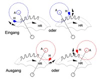
Returning inhibition
With the retracting escapement, the escapement wheel is not only stopped periodically, but, like the rest of the gear train, each time it undergoes a small reverse rotation caused by the regulator (oscillator) (hence the term "retracting" escapement). Energy is withdrawn from the oscillating system (pendulum, balance wheel) (braking), since it has to do some work for the reverse rotation against the driven gear train. This disrupts the vibration. This does not take place during the entire oscillation, but only in the return phases during the movement to the respective reversal point of the oscillator (see animation above). The deceleration depends on the torque driving the gear train and the resulting drive force for the oscillator. In this way, the period of oscillation is influenced by the driving force. If this is not constant (due to a fault in the gear train, a relaxation spring, etc.), there is a gait error .
Spindle escapement

Verge escapement with balance wheel and spring as speed regulator
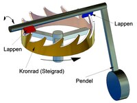
Spindle escapement (principle)

Spindle lock (function)

The first wheel clocks with a spindle escapement used a Foliot (balance, beam balance) as an oscillator. Later the pendulum and balance wheel were used as regulators.
The two sheets ( escapement tabs , spindle tabs ) attached to the shaft ( spindle ) and offset at an angle to each other intervene in the escapement wheel (here crown wheel ) in such a way that it rotates one tooth further with every oscillation of the gear regulator. It rotates by half a tooth pitch with every half oscillation and has an odd number of teeth: 180 ° opposite a tooth there is a tooth gap. For further explanations of the function, see the introduction under "Retracting inhibitions".
The foliot was replaced by the pendulum in the last third of the 17th century after preliminary theoretical work by Huygens . The spindle escapement requires large deflections due to the short lever arm of the tabs (however, a maximum of approx. 100 ° is possible). It is therefore only suitable for light and short pendulums, which are more susceptible to failure than heavy, long pendulums that do not swing much.
At the beginning of the 17th century , however, the combination of the verge escapement with the balance wheel supported by a spiral spring was of great importance . With this, watches became finally mobile, they could be worn on the body ( pocket watches ).
The greater its deflection, the more stable a balance is. The maximum possible oscillation range of approx. 100 ° with the spindle escapement thus represented an obstacle to the production of more precise clocks with a balance-wheel-spiral oscillation system. On the other hand, precise pendulum clocks required very small oscillation amplitudes (approx. 5 ° and below), which, as above described, was not possible with a spindle escapement. As a result, the dormant escapements (Graham escapement for pendulum clocks, cylinder escapement, etc. for balance clocks) were developed.
The spindle escapement was used in pocket watches until the first third of the 19th century, and in stationary watches (e.g. Comtoise watches ) until around 1860.
For his famous H4 watch, John Harrison used a high-quality spindle escapement with diamond pallets.
Cross-flap escapement

Principle of the cross flip escapement H escapement element, A axis of rotation, K coupling element, HR escapement wheel, P pendulum

Ordinary flip escapement with only one pendulum A rotation axis, HR escape wheel, H escapement element, K coupling element, P pendulum
Possible trajectories of the escapement elements with the cross flip escapement A axis of rotation, H escapement element, HR escapement wheel

Cross-flip escapement according to Bürgi (principle) H escapement element, HR escape wheel, K coupling element, W Waag
Principle of an ordinary lay prevention with linkage coupling (one of the two pendulums can be omitted)

A characteristic of this escapement is that the two retarding elements H (sheet metal tabs, claws, pallets, etc.) engaging in the escapement wheel HR driven by the drive are not rigidly connected to each other, but can rotate in opposite directions synchronously around different points A (axes) (hence the Designation ordinary lay). This is achieved by a suitable coupling element K, which can be designed in a variety of ways (sliding joint, tooth engagement, etc.), which enforces the forced operation. The inhibiting elements are usually rigidly connected to a respective oscillator P (Waag / Foliot, pendulum, balance wheel) so that they also move in opposite directions synchronously. But also escapements in which only one escapement element is provided with an oscillator are referred to as cross-lay escapements. In this case, the other inhibiting element is moved by the coupling piece. Watches with a cross-flap escapement are (incorrectly) also those that B. have an armature escapement (or other) cooperating with only one oscillator (usually a pendulum), a second oscillator being driven via a coupling element that only connects both oscillators. The reason for this is probably the aesthetics of two pendulums moving in opposite directions, as the more stable period of oscillation of a cross-flapping pendulum compared to a simple pendulum can at least be questioned. In his watch H1, John Harrison used two tension-spring-coupled, cross-beat balance bars (see grasshopper escapement).
Because of the large number of possible designs, the cross-flap escapement cannot be clearly assigned to the three types of escapement (return, dormant, free). The regular lay principle offers more design options for the escapement than the anchor principle due to the circular trajectories of the escapement elements around two axes of rotation. However, the coupling element (friction) is a disadvantage. Only returning cross-hit inhibitions have become known.
The cross-lay escapement was invented by Jost Bürgi in 1584 . He achieved better gait results than they were possible with spindle escapements. As a coupling element he used two interlocking gears, each provided with a balance beam W (the pendulum was only introduced later by Galileo and Huygens). The escape wheel was very large compared to the coupling gears (not taken into account in the schematic diagram). It is not entirely clear what the better accuracy of this construction was based on. Probably it was less the ordinary stroke principle implemented in this way than the higher quality execution of all watch parts by Bürgi that led to this result. An animation can be found under.
Hook escapement or fallback anchor escapement
Lever escapement with solid anchor

Hook escapement (principle)
Hook escapement (function)

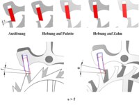
The hook escapement was invented by Robert Hooke in 1676 and introduced into watch technology by William Clement around 1680 . Instead of tabs on the spindle (spindle escapement, see above), a hook anchor made of bent sheet metal is used, which is firmly connected to the transducer (usually a pendulum) via a shaft. The hooks engage radially (the tabs axially) in the escape wheel (here escape wheel ). Their mutual distance corresponds to an odd multiple of half a tooth pitch of the escape wheel, which continues to turn by half a tooth pitch with every half oscillation of the gear regulator. The first hook hit by a particular tooth is the entry hook and the other is the exit hook . The hooks are further from their axis of rotation than the lobes and are shaped to create an uplift (see Resting Escapement ). As a result, the necessary rotary deflection is smaller, and longer pendulums can be used, which are less prone to failure due to their weight. The hook shapes used are similar to one another, but differ in detail. Gear clocks with an armature can also be made flatter, as the axis of rotation of the armature (and thus that of the rate regulator) is no longer rotated by 90 ° against all other shafts of the clockwork like the spindle. The hook escapement replaced the spindle escapement on pendulum clocks at the beginning of the 19th century . The hook escapement has been used since that time, especially for inexpensive watches (e.g. Black Forest watches ).
The fallback anchor works according to the same principle (see animation above), a workpiece made from solid, which is attached to the shaft of the pendulum or the balance wheel. With pendulum clocks it can have its own shaft if the pendulum is suspended from a thread or a thin leaf spring and is connected to the armature with a bracket attached to the armature shaft.
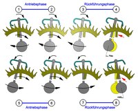
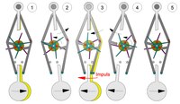
Grasshopper inhibition
Principle of the H1 clock from John Harrison

Grasshopper inhibition (principle) H1, H2 inhibiting elements; G1, G2 weights; D armature and pendulum axis of rotation; A1, A2 stops; AN anchor; D1, D2 axes of rotation of the inhibiting elements; HR escape wheel; P pendulum

Grasshopper inhibition (engagement) H inhibiting element; HR escape wheel; S pivot point

Grasshopper inhibition (undercut) D1 Rotation axis of the inhibiting element

Grasshopper escapement from 1820
Grasshopper escapement with pendulum swing


The grasshopper escapement ( English grasshopper escapement was) 1722-1737 by John Harrison developed and in its marine chronometers H2 and H3 used H1, with whom he the length problem solved. The pallets (restraining elements) are housed on separate arms which are hinged to a balance beam (or pendulum) or an anchor and alternately grip the escape wheel.
Harrison was apparently inspired by the cross-flap escapement of Bürgis, whereby both proceeded from the assumption that two coupled balance bars (foliots) represented a more precise time standard than just one. He modified the cross-flap escapement so that he did not rigidly connect the escapement elements to the coupled arms of this escapement, but instead arranged them rotatably on the arms. Small weights ensured that the pallets were moved into positions determined by stops after engaging the escape wheel. The animation on the right illustrates this for the original version of the grasshopper escapement used in the H1 clock. The balance beams were also coupled with two tension springs (video below), which is not taken into account in the illustration.
Harrison could not use coupled pendulums for his marine chronometers, as their oscillation would have been influenced by the ship's movements in waves (rolling, yawing, etc.), whereas this is not the case for the balance beam (or a balance wheel in the clock H4).
Later developments, which were not limited to the construction of marine chronometers, dispensed with the modified regular lay principle and only used a balance beam or a pendulum, as is explained in the following functional description using a schematic diagram. Only then did the grasshopper inhibition become an independent inhibition.
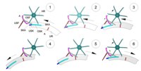
Two inhibiting elements H1 and H2 are movable on circular paths about two axes of rotation D1 and D2 arranged on an armature AN, these axes of rotation in turn moving on circular paths around the axis of rotation D of the armature (see picture). A pendulum P (or balance beam) is firmly connected to the anchor. The blocking elements consist of elongated arms and have the weights G1 and G2, which ensure that the blocking elements are rotated (mostly resiliently) against the flexible stops A1 and A2 fastened on the armature. The stops limit the movement caused by the weights (small forces). When returning (see below), however, the stops must yield slightly, as otherwise the escapement would be blocked. The HR escape wheel is driven by a drive. The arresting elements are prism-shaped at their ends that come into contact with the teeth of the escapement wheel.
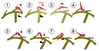
The function of the inhibition can be divided into six phases. In phase 1, the inhibiting element H1 has accelerated the armature and thus the pendulum clockwise, with H1 being moved away from its stop. Both check elements are in engagement with the escape wheel. H2, resting against its stop, was swiveled into the escape wheel on a circular path around D. The escape wheel now exerts a force on the armature via H2, which tries to turn it counterclockwise. However, this is not possible because the pendulum still has kinetic energy. It swings a little further clockwise, so that the escape wheel is turned back a little (return escapement). The work to be done by the pendulum against the force of the escape wheel deprives it of the remaining kinetic energy. It is braked and reaches its turning point. So the pendulum cannot swing freely. That is the main disadvantage of the grasshopper inhibition. Due to the slight reverse rotation of the escape wheel, H1 loses contact with the tooth of the escape wheel and, accelerated by the weight G1, swings against its stop (phase 2). This movement takes place very quickly ("hopping"), which has led to the term grasshopper inhibition. In phase 3, H2 accelerates the armature (pendulum) counter-clockwise and releases itself from its stop. Phase 4 corresponds to phase 1, but for the pendulum swing in the opposite direction. H1, in contact with its stop, has come into engagement with the escape wheel on a circular path around D. In phase 5, H1 turns the escape wheel back a small amount. H2 disengages and the pendulum reaches its reversal point. In phase 6, H1 accelerates the armature clockwise, which means that phase 1 is reached again at the end. The escape wheel is advanced by one tooth.
The contact of a tooth of the escape wheel with the prismatic end of the escapement element can be regarded as a cutting edge bearing (see picture). During the procedure, both twist against each other by S. One with losses due to friction due to mutually shifting movements (such as anchor locks during return or lifting) does not occur. All functions of the escapement are realized by advantageous rotary movements.
The weights G1 and G2 cause torques which try to loosen the locking elements from the respective tooth and try to rotate against their stops. So that the locking elements cannot disengage as a result, one of the two prismatic surfaces of each locking element is inclined at an angle α to the tangent to the circular path by D1 or D2 (see picture). The angle and the prism dimensions are kept small, since otherwise a large return of the escapement wheel would be necessary in order to ensure that the escapement element swings out safely at the end of the engagement phase. Of course, G1 and G2 may only be chosen so large that they do not cause the escape wheel to rotate backwards by the escape elements.
The escapement can be designed pushing, pulling or pulling-pushing or pushing-pulling, depending on whether the escape wheel pulls or pushes the escapement elements. A push-pull version is shown in the adjacent “silhouette image”. Constructions in which the two escapement elements act on escapement wheels of different sizes are also known. A video can be found at.
The use of the escapement in watchmaking remained limited, as the Graham escapement, which was introduced around the same time, had advantages (largely free pendulum oscillation, only dampened by uniform static friction).
Resting inhibition
With the dormant escapement, the escapement wheel is only stopped periodically by the gear regulator. It does not experience any reverse rotation while the gear regulator continues to swing on the supplementary arc , its remaining path until it is reversed. The escape wheel is in almost constant contact with the oscillating system and is only released briefly when it is turned further. This contact is referred to in the technical language as "calming". This means that when the escape wheel is not moving (rest) a tooth of this wheel is constantly in contact with a certain force on a (cylindrical) rest surface of an element (anchor claw in pendulum clocks, balance shaft in balance clocks) of the moving oscillation system and thus exerts a frictional force. It should be noted that in pendulum clocks with dormant escapement, the anchor and pendulum form a firmly connected unit, i.e. the anchor is part of the oscillating system. In principle, this also applies to pendulums that are suspended from a pendulum spring (leaf spring) and z. B. are coupled to the armature with a fork, since they move together during the entire oscillation.
The even rest friction that exists almost during the entire oscillation has proven to be an advantage over the return inhibition, in which the friction only acts in certain oscillation phases, namely during the return (other causes of friction such as bearing friction etc. naturally have more or less effect on all inhibitions and are not characteristic of one). As with the feedback escapement, torque fluctuations of the gear train affect the accuracy, as this changes the contact force acting on the oscillator and thus the static friction, which affects the period of oscillation.
Precise pendulum clocks require long, heavy pendulums with a small oscillation range (approx. 5 ° and below), while on the other hand, large oscillation ranges (approx. 220 ° and above) are necessary for precise balance clocks. These requirements, which cannot be met by returning inhibitions, can be realized with dormant inhibitions.
Uniform (low) friction and optimally adapted oscillation amplitudes are therefore advantages of the static escapement.
The resting surfaces are part of a cylindrical surface whose axis is identical to that of the shaft of the gear regulator (or the armature). The contact surfaces are extremely hard (steel, precious stone pallets) and are usually oiled.
With the reverse escapement, the escapement wheel drives the gear regulator after reversing from reverse rotation to forward rotation until the end of the engagement. This possibility of transferring energy to the regulator, which is not possible with the dormant escapement, is taken over by the so-called lift . After the end of contact between the tooth and the resting surface, the tooth tip slides over an inclined surface ( lifting surface ) of an element of the oscillating system (e.g. anchor claw or pallet) or an edge of the oscillating system (e.g. pallet edge) glides over an inclined surface on the tooth . According to the principle of the inclined plane, the oscillator is given a drive impulse. For more information, see the corresponding escapements.
Graham escapement

Graham escapement

Graham escapement (principle)

Graham escapement (construction)

Graham escapement (function)

Graham escapement (drive impulses)

The Graham escapement is a rubbing, resting escapement. It was developed by George Graham in the early 18th century on the basis of the idea of the same uplift . Major preparatory work is attributed to Thomas Tompion and Richard Towneley .
This inhibition will perform the necessary functions
- Periodic interruption of the escape wheel movement
- Periodic drive of the oscillator
In contrast to return escapements, clearly separated and taken over by different surfaces of two arresting elements ( pallets ) which alternately engage in the escapement wheel driven by the drive and are attached to an armature connected to the pendulum. The obstructing stop surfaces are called resting surfaces, the surfaces that convey the drive impulse are the lifting surfaces (see picture). The lifting surfaces can be understood as inclined planes that can be rotated about the anchor axis. When an escape wheel tooth slides on a lifting surface, a force is applied to the armature. The process is called uplift . The rest surfaces are designed as cylindrical surfaces whose axis coincides with the armature axis.
The radius of the input resting area Re is larger by the width of the pallet (the same for both pallets) than the radius of the exit resting area Ra (entrance and exit result from the direction of rotation of the escape wheel). This defines the position of the pallets on the anchor (apart from the adjusting shift). The centers of the lifting surfaces thus lie on a common circular arc around the anchor axis. The anchor is therefore referred to as having equal arms. If the armature (with pendulum) moves when the escape wheel is stationary (i.e. inhibited), a tooth edge rubs on the resting surface. This removes energy from the oscillating system. The angle through which the pendulum (with armature) moves when the escape wheel is inhibited is called the supplementary arc. With a symmetrical swing of the pendulum, the energy withdrawal is greater at the input resting area than at the output resting area, since the torque exerted on the armature by the friction (force times lever arm; Re and Ra are the lever arms) is greater.
The energy withdrawn from the oscillation system must be returned to it so that the oscillation is maintained. This happens as the escape wheel teeth slide over the lifting surfaces. With the Graham escapement, the concept of the same lift at the entrance and exit is implemented. The inclination of the lifting surfaces is chosen so that the lifting of each lifting surface acts on the armature during an equally large angle of rotation. This angle is called the angle of elevation γ. However, the same lift does not mean, as is usually assumed, that the drive pulse is then also the same (for more information, see the example below).
The pendulums used for Graham escapements, in contrast to those used for return escapements, are relatively long and heavy. The pendulum swing is very small (5 ° and below). The escape wheel and the armature are mostly made of brass. The wheel teeth are pointed and undercut. The pallets are made of hardened steel or ruby and are clamped to the anchor with straps and screws. They can thus be adjusted.
The function of the escapement can be seen in the picture opposite. In phases 1 and 6 the pendulum is at its reversal point after completing the supplementary arc and then swings back with a steady friction. This is followed by the uplift. At the end of the lift, one tooth is released from one pallet and another one strikes the other pallet. This escape wheel movement is called a fall . After the fall, the pendulum swings in the supplementary arc again, still friction, up to the turning point.
The process of lifting is briefly explained using an example. The escapement wheel driven by the drive acts with a force F (tangential to the wheel) during the lifting on the lifting surface (see picture) and generates the driving torque Fa ∙ a (force component times lever arm). Fa and a change during lifting. The energy supplied to the armature (drive pulse) results (in simplified form) by multiplying the drive torque by the lifting angle γ, because the torque acts during this angular movement of the armature. The diagrams show the course of the moments Me (input) and Ma (output). The areas Ie and Ia thus represent the respective size of the drive pulse. It can be seen that with the same increase, the pulses at the input and output are not the same size. The input pulse exceeds the output pulse by 1.14 times. This would result in an asymmetrical oscillation. But now (in this example) the radii of the pallets are Re = 1.1 Ra. The energy loss at the input is 1.1 times greater than at the output. The higher input pulse practically compensates for this difference, so that a symmetrical oscillation can be achieved. The escapement therefore offers optimization options through a suitable choice of parameters.
The development of the Graham escapement was one of the greatest innovations in the history of mechanical watches. All escapements for precise pendulum clocks (with the exception of tower clocks) are based on Graham's principle and are consequently very similar in structure. Free escapements (Riefler, Strasser) were only used for watches with extreme requirements.
Amant escapement (also: pin escapement, scissor escapement, Mannhardtgang)

Amant escapement

With the Amant escapement , the pivot point of the armature is relatively far from the pivot point of the escape wheel. As a result, the anchor arms are elongated and have a small opening angle. The hooks engage in axially parallel pins on the toothless escape wheel. The input hook acts radially from the inside out on the pins, the output hook from the outside in. The Amant escapement enables a very precise rate and was often used in tower clocks .
Cylinder escapement

Cylinder escapement


The cylinder inhibition in a cylinder plant has, instead of an anchor and an anchor wheel a cylinder with cut-outs, the so-called passages , which engage, and a cylindrical gear (escape) with set high, specifically shaped teeth directly in the designed as a hollow cylinder balance staff. The cut-out cylinder only engages over one tooth (half tooth pitch) of the escape wheel and therefore has a very small diameter. This escapement was invented in 1695 by the English watchmaker Thomas Tompion and decisively improved by George Graham in 1720. Because of the extraordinarily high demands on manufacturing accuracy, it was only manufactured in large numbers about 100 years later. It replaced the verge escapement in portable watches.
The balance shaft is composed of a hollow cylinder (tube) and two tampons (with bearing journals) pressed into it. In the area of the escape wheel, the tube is cut to a little more than half of its circumference. The escape wheel has a crown-like shape, its functional elements for inhibiting and lifting - the shoes - are on a second level. The toe of the shoe rests against the inner or outer surface of the cylinder in the resting phases (escape wheel does not move). The outer side of the shoe is designed as a lifting surface. There is space for a tooth shoe in the pipe. The inner surface of the cylinder acts as an exit stop. When the partial tube (channel) connected to the speed regulator is turned back, the toe of the shoe is released, the escape wheel continues to rotate, whereby the lifting surface of the shoe acts on the exit edge of the channel. After the lift , the tip of the next shoe falls onto the outer surface of the channel (entrance stop).
The cylinder escapement is intended for portable watches with a balance. Cylinder escapement watches are not as accurate as those with anchor escapement, but they can work satisfactorily with adequate lubrication. In order to allow a particularly large swing range of the balance, the escapement only acts on a single escape wheel tooth (shoe). This is lifted from the wheel plane with the help of a supporting shaft in the second plane ( tooth carrier ). So that the cylinder does not hit the wheel mandrel, the cylinder is trimmed again at the level of the wheel plane. To prevent the tooth and cylinder from getting stuck , a bounce pin is attached to the balance tire which, if the oscillation range is too large, hits a stop pin (often springy) on the plate. Phases 1 and 4 shown in the picture represent the end positions (reversal points) of the balance oscillation.
The two functional surfaces for lifting - lifting surface and opposite edge - are distributed the other way around compared to the Graham escapement.
The original form of the escapement had no passage for the wheel mandrel. Because of the similarity of the gutter with a trough used to feed pigs, it was called the sautry inhibitor .
The cylinder escapement in wristwatches was mainly used for cheaper models from around 1920 to 1940, after which it was abandoned in favor of the lever escapement because of the poorer accuracy .
Duplex escapement

Duplex escapement

Duplex escapement (principle)

Duplex escapement (function)

It is an escapement for small watches with a balance-spring system. The escapement wheel of the duplex escapement has two rows of teeth in two planes, the first for escaping ( resting teeth ), the second for lifting ( tusks ). Inhibiting and lifting do not take place twice, but only once for each oscillation of the balance wheel (see pictures, balance wheel not shown). The advantage is that the lift is favorable, namely in the middle position of the balance, that is, at the moment of its greatest kinetic energy. There is no anchor. During the rest, the escapement teeth rest against a cylinder ( roller ) that is coaxial with the balance wheel, which they can pass through a slot on the cylinder, whereby the escape wheel can continue to turn. During the fall (further movement of the escape wheel) a lifting tooth hits the lifting arm ( lever stone , drive stone ) on the balance and accelerates it. When the balance wheel swings back, there is a slight return when the rest tooth passes the roller incision (phase 6).
The duplex escapement was invented by Jean-Baptiste Dutertre around 1730 and , according to other sources, by Pierre Le Roy in 1758 . It was used in pocket watches, but this was soon abandoned because the jamming teeth passed through the roller slot, which was difficult to control in practice.
Comma inhibition

Comma inhibition (structure)
Comma inhibition (function)
The comma escapement was designed by Jean Antoine Lépine in the middle of the 18th century for small watches with a balance- wheel -spiral oscillation system. As with the cylinder and the duplex escapement, the intention was to let the escape wheel and oscillation system work together directly without an intermediary additional part (armature). This was already the case with the verge escapement, but cylinder, duplex and comma escapement allowed large oscillation ranges of the balance and thus better accuracy. Of the three escapements mentioned, the cylinder escapement prevailed, which was industrially manufactured in large numbers in the 19th century. For more precise watches, however, Glashütte and Swiss lever escapements were used from the middle of the 19th century.
The serious disadvantage of the decimal point escapement is the unavoidable friction with this construction, which led to great wear, so that the escapement was hardly used.
The structure of the escapement can be seen in the picture opposite. The escapement wheel HR, which is driven by the drive (not shown), has flattened cylindrical pins ST (usually twelve) attached to support arms TA. When the escape wheel is turned, these pins (their axes) move on a circular path that runs through the axis of the balance shaft. The balance shaft therefore has an incision in the area of the escape wheel, so that only a circular segment-shaped cross section KS remains. If the balance shaft is in a suitable position, it does not constitute an obstacle to the rotation of the escape wheel.
The comma-shaped impulse finger IF, which gives the escapement, is attached to the balance wheel in the area of the circular segment cross-section. The pulse finger has a recess with the inner cylindrical surface RFI, the axis of which coincides with the axis of the balance shaft. The diameter of this area is slightly larger than the diameter of the escape wheel pins. RFI is the inner of the two resting surfaces of the pulse finger. The outer one is the RFA area. During certain phases of the balance oscillation, a pin on the escape wheel rests against one of the two, preventing it from turning, which is known as rest. Since the balance wheel and thus the impulse finger also rotate during the rest, the pen rubs on the respective rest surface (the technical term is "restraibend"). The HF surface of the impulse finger can be understood as a curved, inclined “plane” through which a drive impulse is given to the balance when an escape wheel pin slides along. This is called the lift and the area is called the lift area.
The function of the escapement is shown in the picture opposite. In phase 1 the balance wheel swings counter-clockwise. One pin of the escape wheel is released from the inner resting surface of the pulse finger. The lifting occurs when the escape wheel moves in phase 2, when the pin slides on the lifting surface (when the balance is swung back, there is no lifting, ie the balance is given a one-sided drive impulse). In phase 3, the escape wheel has rotated so far that the following pin comes to rest against the outer resting surface. The balance wheel swings in phase 4 up to its reversal point and moves backwards in phase 5 in a clockwise direction. The dimensions of the escape wheel and impulse finger are chosen so that the end of the impulse finger can swing past the pen without touching it. In phase 6, the pen leaves the outer resting surface and moves into the inner resting surface (slight movement of the escape wheel). When the pen plane slides on the edge of an impulse finger, a very small lift is effective (inclined plane). During the rest of the movement of the balance, the pin rests on the inner resting surface (phase 7), whereby the turning point of the balance is reached in phase 8. This is followed by phase 1 again. During a balance oscillation, the escape wheel is advanced by a pin (“tooth”). As a comparison of phases 4 and 8 shows, oscillation ranges of almost 360 ° can be achieved. The limiting conditions are that the pin at the turning points of the balance must on the one hand still be in contact with the outer resting surface (phase 4) and on the other hand the circular segment of the balance shaft must not touch the support arm of the pin (phase 8).
Free escapement
With a free escapement, there is another part that rotates back and forth around its own axis between the escape wheel and the gear regulator. This part is the anchor or a similar part with a different name. In the rest phase of the escape wheel, it is decoupled from the regulator and together with the escape wheel at rest. The friction between the inhibiting parts that is present in the static escapement in this phase is eliminated, the oscillation of the gear regulator is less disturbed, it swings "freely". The necessary coupling with the gear regulator is only present in the phases of uplift and the next fall of a locking tooth against a locking hook. There are also minor frictional losses, so that the avoided friction between the inhibiting parts cannot be fully used.
English lever escapement or pointed lever escapement

Pointed anchor escapement
Pointed-tooth anchor escapement (principle)

It is an escapement for small watches with a balance-spring system. It was invented by Thomas Mudge in 1757 as the first free escapement and for a long time it was the best escapement for portable watches.
The function of the escapement is the same as that of the Swiss lever escapement and is described there.
The anchor A originally consisted of one part, but later of two metal parts, the massive anchor body AK and the anchor fork AG. The blocking elements H (pallets) were an integral part of the anchor body and had stop surfaces RF (resting surfaces) and inclined planes HF (lifting surfaces). The HR escapement wheel had sharp teeth. Steel and brass were used as materials (see picture).
Later versions were provided with precious stone pallets embedded in the anchor body (concealed in horizontal slots, as was later also the case with the Glashütte anchor escapement, but with flat lifting surfaces). This material was then also used for the lever stone.
The straight lines connecting the pivot points (axes) of the escape wheel and lever as well as of balance and lever are perpendicular to each other (in contrast to the Glashütte and Swiss lever escapement).
During the assembly of the escapement, the anchor fork and anchor body could be rotated relative to one another around the anchor axis DA in order to establish the correct meshing relationships with the escape wheel and the balance. Both parts were then firmly connected to one another by pinning (pin VS).
When the escapement wheel driven by the drive is turned, the tooth tips slide on the inclined planes (the lift) of the pallets and thus transmit a drive pulse to the armature or the balance wheel. It is said in technical jargon that the lifting of this escapement is on the pallets.
The two major disadvantages of the escapement were that, on the one hand, the pointed teeth could be easily deformed in the event of vibrations, but also during normal function and, on the other hand, there were only limited possibilities for adjustment. The lubrication of the escapement (permanent lubrication) was also inadequate. The escapement was therefore no longer competitive with the Glashütte lever escapement and later with the Swiss lever escapement from the middle of the 19th century.
Glashütte lever escapement

Glashütte anchor escapement (principle)

Glashütte lever escapement (oil problem)

Glashütte lever escapement (piston tooth)
It is an escapement for small watches (portable watches) with a balance-wheel-spiral oscillation system. Since the shafts of the escape wheel, lever and balance are in a straight line, one speaks of an escapement in a straight line.
The escapement was developed in the middle of the 19th century by Ferdinand Adolf Lange in Glashütte / Saxony. For the first time, it has all the features that make an escapement suitable for portable watches with high accuracy. These features, as well as the function, which is the same as that of the later developed Swiss lever escapement, are explained in the description of the latter. Only a few special features of the escapement are described here (see picture).
Armature A, whose center of gravity lies in its axis of rotation DA, and escape wheel HR are made from a gold alloy that has been made wear-resistant through a special process (hammering). In addition, this alloy did not chemically attack the oil required to lubricate the escapement.
The armature movement is limited by a limiting pin BS attached to the armature, which protrudes into a hole in the base plate (plate) and rests against the wall of the hole in the end positions. The gemstone escapement elements H (pallets) are embedded in horizontal slots in the anchor so that they are barely visible from above (i.e. when the escapement is installed). The pallets have a cylindrically curved surface on which the teeth of the escape wheel slide. Only the curved surface protrudes from the anchor socket. The escape wheel carries piston teeth. Like the pallets, these have an inclined plane. Depending on whether the edge of the pallet slides on the tooth plane or the edge (or rounding) of the tooth slides on the pallet plane, it is said that the lift is on the pallet or on the tooth of the escape wheel. The advantage of piston teeth is that, on the one hand, the risk of deformation of the teeth (as in the case of pointed tooth escapement) is counteracted and, on the other hand, the lifting of the armature is increased. The energy supplied to the armature or the balance wheel is increased (with the same drive torque) (or the drive must deliver a lower torque with a certain required drive pulse).
The designation piston teeth goes back to the similarity of these (in the first versions rounded) teeth with a club, formerly also called piston (see picture).
During the lifting (sliding of a tooth on the curved inclined "plane" of the pallet) a very small (variable) angle α arises between the oiled pallet and a tooth of the escape wheel (see picture), which even passes through the value zero on the output side during this process . On the one hand, this angle is desirable because the capillary action of this wedge transports oil to the contact point (point of friction) between the pallet and the tooth. If the pallet surfaces were not arched, there would be two flat surfaces facing each other, which tend to stick to one another (adhesion). This would have a negative effect, especially if the viscosity of the oil changes over time (at least that is what is feared). The curvature of the pallets effectively suppresses adhesion.
It is not entirely clear why the pallet arch is flush with the anchor socket. In principle, the pallets could also protrude a little. Possibly. the oil problem played a role again. The area between the end of the bulge and the armature socket could act as an oil depot and the oil in turn could be transported to the friction point by the wedge capillary action (shown schematically in the picture).
The great disadvantage of the escapement was that it could not be adjusted when installed (moving the pallets; limitation) and only a few adjustment options were available. In order to carry out the adjustment, it was necessary to remove the escapement and reinstall it to check the adjustment. This work also required great skill (e.g. setting the limiting pin , taring the anchor). This subsequently led to the development of the Swiss lever escapement, which offered a significantly simplified adjustment and thus the prerequisites for series production.
Swiss lever escapement

Swiss lever escapement (principle)
Swiss lever escapement with escape wheel and anchor with fork and armature shaft, safety knife not shown
Swiss lever escapement (function)

Swiss lever escapement (anchor arms)

Swiss lever escapement (lifting)

Swiss anchor escapement (safety)

Swiss lever escapement (piston tooth)
The Swiss lever escapement is characterized by the special shape of the anchor and gear wheel, which means that the drive is distributed between the anchor stones (pallets) and the lifting surfaces of the escape wheel teeth, thus enabling the manufacture of high-precision wristwatches. It developed at the end of the 19th / beginning of the 20th century in Germany from the Glashütte lever escapement. The original name was piston tooth escapement. In Switzerland, watches with this escapement were then mass-produced, so that the name Swiss lever escapement prevailed.
Apart from very cheap watches, this escapement is used in most portable mechanical watches (wristwatches, pocket watches) with a balance-wheel-spiral oscillation system, but is also used for larger ones, such as alarm clocks, table clocks, etc.
The escapement wheel, lever and balance wheel shafts lie in a straight line. This is why one speaks of an escapement in a straight arrangement.
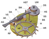
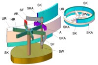
In a hardened steel piston-tooth escapement wheel HR (see picture), which is driven by the drive, two escapement elements (pallets) H, preferably made of synthetic ruby, engage alternately. These have a stop surface (rest) RF and an inclined plane (elevation) HF. The pallets are attached to an anchor A, which can move around the axis of rotation DA. The anchor is usually also made of steel, but other materials are also used. The movement of the armature is limited by two limit pins BS. Other limitations are also occasionally encountered. Fixed to the balance shaft UW is a double disk DS, which consists of the lever disk HS and the safety disk SS (or safety roller ). The lever block (ellipse) HST is attached to the lever disc. This is also mostly made of synthetic ruby. When the balance wheel moves around its axis of rotation, the lever stone can engage in an incision GE in the lever fork, so that the movements of the balance wheel and the armature can influence one another. The safety knife (safety pin) SM has a function that secures the rest position of the anchor.
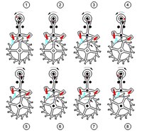
The inhibition function can be seen in the picture opposite. In phase 1 the balance (not shown), swinging back from its reversal point, moves counterclockwise. One tooth of the escape wheel rests on the resting surface of the entrance pallet so that the wheel is prevented from moving. A limiting pin prevents the armature from moving counterclockwise about its axis of rotation. The safety knife is very close to the safety disc, but does not touch it. In phase 2, the lever block moves into the cutout of the anchor fork and thereby rotates the anchor. The safety knife does not hinder this movement because the safety disc is provided with a recess. The armature moves away from the limit pin and raises the entry pallet (first anchor pallet in the direction of rotation of the escape wheel). Since the escape wheel, driven by the drive, exerts a force on the pallet, a frictional force acts. This has to be overcome and the balance must do the so-called release work. The release action is a disturbance of the free oscillation of the balance and should therefore be as small as possible. The path w that the pallet has to cover on the tooth when it is triggered is therefore kept very small. At the end of the release, the escape wheel rotates, one edge of the tooth reaches the lift of the pallet and slides on it, whereby the armature is moved further and gives a drive impulse to the balance wheel via the lever stone. In phase 3 the tooth leaves the pallet and the escape wheel moves until another tooth strikes the resting surface of the output pallet. The armature rests on the now other limiting pin, the lever stone leaves the fork cut and the balance swings freely to its reversal point (phase 4). The safety knife is located near the safety disc, but does not touch it. In phase 5, the balance wheel now swings clockwise and the lever block causes the release on the output pallet, whereby the release work has to be done again by the balance wheel. Starting with phase 6, the escape wheel rotates and a tooth again slides on the lifting surface, but now on the one on the starting pallet. The balance wheel is given a clockwise drive pulse. In phase 7 the process is finished, the lever block leaves the fork and in phase 8 a tooth hits the entrance pallet again. The anchor comes to rest on the limiting pin. This means that phase 1 is reached again. The escape wheel has turned one tooth further.
So that the escapement could be used for portable watches, it had to be designed to be largely vibration-resistant. This is achieved through three design features that were already present in the pointed lever escapement and the Glashütte lever escapement.
- Draw angle (see picture)
The pallets are inclined at a certain angle (pulling angle). This causes torques during rest due to the forces F1 and F2 of the escape wheel and the perpendicular distances between these forces a and b to the anchor pivot point, which pull the anchor against the limiting pins during the free oscillation of the balance. Possibly. In order to cause a disturbance, vibrations acting on the watch would have to be so great that they overcome these torques (i.e. loosen the armature from the respective limiting pin).
- Safety knife
Should the anchor move away from the delimitation pin due to vibrations during the rest, despite the pulling angle, the safety knife SM rests against the locking washer. Although this briefly disrupts the balance oscillation due to the resulting frictional forces and thus leads to a gear deviation, a serious malfunction does not occur.
- Fork horns
The so-called fork horns GH of the armature prevent undefined movement of the armature in the phase because the safety knife moves in the cutout of the safety disc and is therefore not effective. If the watch is jolted, they rest against the lever block, which causes a rate deviation but no malfunction.
For the structural design of the escapement it would be ideal if the drive impulses and the release work in both directions of oscillation of the balance wheel were the same. However, this is not simply possible. The sizes depend on the length of the anchor arms. If the release work is to be the same, the lever arms c of the armature for the resting surfaces must be of the same length (see picture). The balance must then work against the same torque when triggered. If, on the other hand, an equally large drive pulse is required, the lever arms to the center of the lifting surfaces are decisive. The same torque is then given to the balance by the lifting. The release resistance disturbs the isochronism more than unequal drive impulses. A compromise is usually chosen in terms of construction (unequal arm anchor). In principle, it would be possible to balance the release work and the drive pulse with an escapement. For this purpose, the release path w would have to be adjusted unequally in the case of an armature with symmetrical lifting, B. different widths of pallets and / or different gradients of the elevation bring about the desired result.
The escape wheel has piston teeth. Like the pallets, these have an inclined plane. Depending on whether the edge of the pallet slides on the tooth level or the edge (or rounding) of the tooth on the pallet level, one speaks of the fact that the lift is on the tooth or the pallet of the escape wheel (see picture). The entire lifting process consists of both, with the greater part lying on the pallet.
The advantage of piston teeth is that, on the one hand, the risk of deformation of the teeth (as with pointed tooth escapement) is counteracted and, on the other hand, the lifting of the armature is increased (e> f). The energy supplied to the armature or the balance wheel is increased (with the same drive torque) (or the drive must deliver a lower torque with a certain required drive pulse).
The shape of the piston teeth was created by gradually modifying the pointed teeth by means of an inclined plane, rounding and clearance for the pallets immersed in the escape wheel (see picture). The rest edge is not rounded because the release path can be better adjusted under visual control and the release is more precise. The name piston tooth is based on the resemblance to a club, formerly also known as a piston.
The escapement must be oiled. To do this, a small amount of oil is placed on the lifting surfaces of the pallets (other methods are also known), which sticks there due to the adhesion. The negative influence of the adhesion feared with the Glashütte anchor escapement is negligible, since the amount of oil applied is extremely small. Attempts have been made and continue to be made to operate the escapement without oil by means of suitable material combinations.
The suitability of the escapement for series production is due in particular to the fact that it is much easier to adjust than the Glashütte lever escapement. With a built-in anchor, the pallets can be moved with simple tools in the anchor slots and the aisle can be set up. The anchor is then removed only once and the pallets are secured in position with shellac. The limiting pins are also z. B. adjustable by minimal bending (there are also known as eccentric pins rotatable about an axis). These advantages, as well as the use of steel instead of a gold alloy, led to the Swiss lever escapement becoming the standard for precisely portable watches.
For watch professionals:
The Swiss lever escapement runs, divided into parts, as follows:
- Double roller / lever disc : supplementary arc rising, then falling (approx. 220 ° to 270 °) - release (approx. 8 °) - impulse before and after the dead point (approx. 30 °) - supplementary arc rising, then falling (approx. 220 ° to 270 °) etc.
- Anchor : rest - release (2 ° to 4 °) - impulse (approx. 10 °) - lost path (safety from falling of the wheel to the limiting pin) (30 ′ to 1 °) - rest
- Wheel : rest - geometric return (0 ° 15 ′) and dynamic return (0 ° 0′15 ″) - impulse (approx. 10 ° 30 ′) - outer or inner fall (1 ° to 2 °) - rest
Pin lever escapement

Pin lever escapement, functional model

Pin lever escapement (principle)

Pin anchor escapement (rest, lifting, securing)

With the pin lever escapement , there are no anchor stones, but hardened, vertical steel pins engage in an uncomplicated escape wheel. The pin lever escapement was developed by Louis Perron in 1798 . Georg Friedrich Roskopf modified them and produced the pin lever movement in his company from 1868 for his Roskopf clocks in series. That is why it is often referred to as the Roskopf escapement, even though the respective construction may not correspond to the changes introduced by Roskopf.
The escapement was used for simple portable watches (wristwatches, pocket watches) with a balance-wheel-spiral oscillation system and often replaced the clocks with cylinder movements. The pin lever mechanism was also used for larger ones, such as alarm clocks and table clocks.
Both the straight arrangement (the escapement wheel, anchor and balance wheel are on a straight line) and right-angled designs (as with the pointed escapement) were common.
An escapement wheel HR (see picture), which is mostly made of brass and is driven by the drive, alternates between two hardened cylindrical steel pins pressed into an armature A (mostly brass), which act as restraint elements H. The armature can rotate around the axis DA. The movement of the armature is limited by two limit pins BS. A double disk DS, which consists of the lever disk HS and the safety disk SS, is permanently connected to the balance shaft UW. The semicircular lever stone (ellipse) HST is attached to the lever disc. This is also mostly made of steel. When the balance wheel moves around its axis of rotation, the lever stone can engage in an incision GE in the lever fork, so that the movements of the balance wheel and the armature can influence one another. The safety knife (safety pin) SM has a function that secures the rest position of the anchor.
The teeth of the escape wheel are provided with inclined planes, so that when one of the two steel pins glides on one of these planes, a drive pulse is transmitted to the balance wheel by the armature movement (lifting) caused by this. In technical terminology, this is referred to as on-tooth lift. However, since the tooth edge also briefly slides on the steel pin at the beginning (lifting on the pin), one speaks of the fact that with the pin anchor escapement, the lifting is predominantly on the tooth (see picture).
The function of the escapement is the same as that of the Swiss lever escapement and is described there. It should only be noted that instead of pallets there are steel pins and the respective inclined plane is not on the pallet, but on the escape wheel tooth.
The shock resistance required for portable watches is also achieved with the same means as described for the Swiss lever escapement. The angle α (here called the angle of repose), through which a torque F ∙ a arises around the armature axis, which pulls the armature against a limiting pin during the free oscillation of the balance, is, however, shifted from the arresting element to the escape wheel tooth (see picture).
In addition to the simple structure (stamped and turned parts) and the inexpensive materials, the escapement was also suitable for the series production of watches, which were not subject to high quality requirements, thanks to the simple adjustment. The adjustment could be carried out with the escapement installed and was limited to the fact that the release path w (rest) and the drive pulse were approximately symmetrized by minimal bending of the limiting pins or the fork neck on the armature. Often the limiting pins were also left out. The armature movement was then limited by placing the pins on the tooth base (e.g. with Roskopf). In the case of watches that are less sensitive to vibration (e.g. alarm clocks), the safety knife (safety pin) was also omitted and the function was ensured by a suitably shaped fork horn GH, which was placed on the balance shaft UW. Instead of the lever, a simple steel pin SST pressed into one arm of the balance U was used. The balance shaft was semicircular in the area of the horn (see picture).
Roskopf used balance shafts on which the safety disc was not pressed, but was rotated together with the balance shaft and carried an FI finger attached to it (instead of a lever stone). There was no lever disk.
Pin lever escapements were used in the most varied of versions and in large numbers until well into the last third of the twentieth century for inexpensive watches, which were often underestimated in their accuracy and lifespan from around 1970 onwards. Only the mass production of quartz watches put an end to this.
Chronometer escapement

Le Roy chronometer
Le Roy chronometer escapement (principle)
Le Roy chronometer escapement (function)

Le Roy chronometer escapement (engagement)


Earnshaw chronometer escapement (principle)

Chronometer escapement


It is an escapement for small watches with a balance-spring system. Because of its sensitivity to shock, it was only of greater importance for (gimbal-mounted) marine chronometers, with the help of which the geographical longitude could be determined on the high seas. Pocket watches were also built with this escapement. However, the disturbances caused by the movement of the watch led to the more robust Swiss lever escapement becoming established for portable watches. With the introduction of quartz watches and GPS navigation, the need for mechanical chronometers came to an end.
The chronometer escapement was invented by Pierre Le Roy in the middle of the 18th century. Together with Ferdinand Berthoud , he completed the first marine chronometer ( length watch , later chronometer ) in France in 1761 . In England, John Arnold and Thomas Earnshaw worked on similar concepts. Around 1790 Earnshaw brought the escapement into the forms that were used until the end.
While John Harrison equipped his marine chronometers H1 (1735) to H4 (1759) with return escapements (grasshopper escapement, spindle escapement) at about the same time, the chronometer escapement as a free escapement represented the much more modern concept from today's point of view. that the first efforts to use the lever escapement known from large clocks for small watches with a balance-wheel-spiral oscillation system revealed some difficulties (Thomas Mudge did not invent the pointed lever escapement for portable clocks until 1760). In the case of anchor escapements, a drive pulse is fed to the transducer via inclined planes (elevation) (cf. Swiss anchor escapement). The rubbing movement during this process and the necessary lubrication (with the rapidly aging oils available at the time) was recognized as a hindrance to the manufacture of precise small watches. Therefore, a search was made for ways to transmit the drive impulse to the balance wheel with little friction and without lubricants.
The solution to this problem chosen by Le Roy can be seen in the picture opposite. An escape wheel HR driven by the drive can be brought into engagement with a stop block AK and an armature A. The stop block, like two control cams SK provided with rounded switching edges SKA, is arranged directly on the balance tire UR or on a second tire that is firmly connected to the balance shaft UW (above or below the balance). A switching shaft SW carries the armature and two control fingers SF, which work together with the control cams. The control fingers and the armature are firmly connected to the shaft in a certain angular arrangement.
The functional sequence is as follows (see picture). The balance wheel has passed its turning point in the clockwise direction and is swinging in the opposite direction, so that the stop block moves towards the escape wheel (phase 1). One tooth of the escape wheel rests on the front anchor claw and generates a (very small) torque which presses the upper shift finger OSF with little force against the upper shift cam OSK. The tire UR (the balance wheel) continues to move and the switching edge SKA of the lower switching curve rotates the lower switching finger USF, so that the upper switching finger and armature A also move clockwise (phases 2 and 3). The balance wheel has to do the release work because the armature has to be turned against the frictional resistance of the tooth pressing on the armature pawl so that the tooth is released. The stop block is located in the area of a tooth of the now rotating escape wheel, which strikes the rear anchor claw at the end of this process. The tooth in engagement with the stop block gives the balance a drive pulse. In phase 4 the balance wheel swings to its reversal point. During the backswing (phase 5), the stop block moves past the tooth without touching it. The switching edge of the upper switching curve reaches the upper stop finger and turns it. Again, the balance has to do release work, since a tooth has to be loosened from the rear anchor claw. The escape wheel moves and hits the front anchor claw. After the balance has passed the turning point again, phase 1 is reached again when swinging back.
The balance wheel receives only one drive pulse during one oscillation, but has to do the triggering work twice. Meanwhile, the escapement wheel moves one tooth further in two steps. While the drive pulse is being issued, the tooth moves on the stop block in a shifting manner (twice by the amount v, see picture) and rolling, which has proven to be useful for the further development of the escapement (usually no lubrication required). In contrast, the release mechanism was changed in later versions. The reason for this was that the shift fingers dragging the control cams (even if only slightly) and the triggering work that was necessary twice hindered the free balance oscillation. The complicated structure and the lack of adjustment options also spoke against this design.
Earnshaw and Arnold solved the release problem with an extremely filigree leaf spring F (called a gold spring), which is held in a so-called resting piece RS and clamped at a (not rotatable) (see picture). In area b the spring is called the rest spring and in area c the release spring. The rest piece has a stop RST for the escape wheel teeth, which was later designed as a half-round stone (hearth stone). The rest piece itself rests against the stop pin AS by a slight bias of the spring, which was replaced by an adjusting screw in subsequent designs. A disk HS (lifting disk), which has a recess with the stop surface HST, is attached to the balance shaft. The escape wheel tooth transmits the drive impulse to the balance wheel via this surface (analogous to Le Roy). Later a precious stone was used instead of the stop surface (the so-called lifting stone or impulse stone). In addition, the release disc ASB with the release stone AST is attached to the balance shaft. When the balance vibrates counter-clockwise, it triggers the release by deflecting the spring and thus the rest piece. Although the spring is filigree, it can transfer the force required for triggering to the rest piece, since it protrudes very little over the rest piece. When triggered, the spring bends only in area b. The rest piece lifts off the stop pin and releases the escape wheel. When the balance wheel swings back, the release stone lifts the spring off the rest piece resting on the stop pin and bends it in area c. The disturbance of the balance oscillation caused by this is negligible, since an extremely small force is required because of the large spring length that is now effective.
The balance wheel receives only one trigger impulse per oscillation and (in contrast to Le Roy) only has to do the triggering work once.
Denison gravity check (Westminstergang)
Denison escapement, 6-armed

Denison inhibition (principle)
Denison inhibition (function)

With the Denison gravity escapement , which is used exclusively for tower clocks , two levers on the side temporarily and alternately lock the escape wheel. One of the levers is deflected (lifted) a little when the escape wheel is turned further. The lever, driven by its own weight, falls back into its starting position, pushing the pendulum in front of it and transferring kinetic energy to it.
The Denisongang is common in tower clocks in England, among other things a "double three-armed Denisongang" is used in the tower clock of Big Ben of the Palace of Westminster .
The structure of the escapement can be seen in the picture opposite (other designs are also known).
The shafts or axes D (for the pendulum P), DH (for the lever arms HA) and the main shaft HW are mounted in the frame (not shown). The AS stop pins are attached to the frame. Fixed to the main shaft are two three-armed switch stars SST and a flange that carries three switch cams SN offset by 120 °. The two switching stars are offset from one another by 60 °. The main shaft with its components corresponds to the escape wheel in other escapements, i.e. the last wheel of a drive that should move in simultaneous steps. The lever arms each have a switch nose SNA with stop surfaces (acting as an inclined plane) for the switch cams and a lever pin HS. A stop H (restraining element) is attached to each lever arm, this being located on the front side of one arm and the rear side of the other. The two switching stars are arranged on the main shaft in such a way that they can be blocked by the stops if they are rotated. The movement of the lever arms is limited by two stop pins AS. Often a vestibule W is attached to the main shaft to dampen the rotation of the main shaft (possibly also on a second shaft driven by the main shaft via gear wheels). Ideally, the pendulum and lever arms rotate around a common axis of rotation. For structural reasons, however, there are usually separate axes of rotation. As a result, when the pendulum swings, there is a (small) relative movement between the lever pin and the pendulum arm, which results in low friction losses.
In phase 1 (see picture) the pendulum moves through its central position counterclockwise. The main shaft has rotated so far that one arm of the front switch star is in contact with the stop on the right lever arm. During this movement, a switching cam lifted the right lever from its stop pin via the stop surface of the switching nose (supply of potential energy). The pendulum can initially swing to the position marked in yellow without having to lift the lever arm and then swings with the lever on it to the reversal point (phase 2). One arm of the front star switch is released from the stop and the main shaft driven by the drive rotates until one arm of the rear star switch rests against the rear stop (not visible) of the left lever. The left lever arm is raised by a switch cam. The pendulum carries out the so-called release work, since a force is required to move the stop on the star arm because of the friction that occurs. Energy is thus withdrawn from the pendulum. Since further losses occur (e.g. bearing friction), the pendulum must be periodically supplied with energy in order to maintain the oscillation amplitude. This takes place during the back swing (phase 3) after the pendulum has passed its turning point. The pendulum again reaches the position marked in yellow, up to which the pendulum could swing without a lever resting on it. The lever arm is now still on the pendulum, since the switching cam no longer hampers the lever movement and accelerates it due to its weight (therefore gravity inhibition) in a clockwise direction until it hits the stop pin. A drive impulse (kinetic energy) is given to the pendulum.
In phase 4, the pendulum does the release work at the left stop. When swinging back, it receives a counterclockwise drive impulse. Phase 5 corresponds again to phase 1. After each pendulum oscillation, the main shaft (the escape wheel) has rotated a further 120 °.
A video and animation can be found at.
(see for this escapement also: intermediate lift )
Free spring escapement from Riefler

Free spring escapement by Riefler (principle)

Riefler's free spring-force escapement (function)

Free spring escapement by Riefler for balance-wheel oscillators (principle)

Free spring escapement from Riefler

This escapement was developed by Sigmund Riefler for precision pendulum clocks in 1889 .
The escapement principle can be used for pendulum clocks as well as for clocks with a balance-wheel-spiral oscillation system. The escapement only became important for pendulum clocks.
The escapement ensures a largely interference-free oscillation of the oscillator.
The structure of the escapement for pendulum clocks can be seen in the schematic diagram opposite. A pendulum P swings about the axis of rotation D. The axis of rotation is formed by a cutter bearing, consisting of two prisms PR attached to the frame G and a cutter SN. The prisms are very flat (for example, keyways scored in agate slabs). To prevent the cutting edges (and thus the anchor) from slipping, delimiting side plates are attached to the prisms at one end of the groove (not shown in the picture). An anchor A, which carries two semicircular restraint elements (pallets) H, is firmly connected to the cutting edge. These engage alternately in two escapement wheels RR (resting wheel) and HR (lifting wheel), which are attached to a common shaft. The escape wheels are driven by the drive. The arrangement of the toothing of the escapement wheels to one another results in a resulting contour RK, which is decisive for the interaction with the escapement elements. Only one escape wheel could have been used and given this contour, but would probably have been more difficult in terms of production than using two wheels. Only partial areas of the toothing of both wheels are effective, namely the inclined planes HF (lifting surfaces) and the stops RF (resting surfaces). The pendulum P is connected to the cutting edge via two pendulum springs PF (leaf springs). In general, the ends of leaf springs move approximately on a circular path with small deflections, the center of which, however, is not located at the clamping point, but a little in front of it. The springs are therefore clamped in the cutting edge in such a way that this so-called bending point (bending axis) coincides with axis D of the cutting edge bearing and thus also of the armature. Apart from the springs there is no other connection between the pendulum and the anchor. The energy necessary to maintain the oscillation is transmitted exclusively via the springs. The feathers are approx. 0.1 mm thick.
In phase 1 (see picture) the pendulum swings clockwise and is close to its central position. The inhibiting element on the input side has left the rest surface of the escape wheel. The exit-side locking element is at the beginning of the lifting surface. The escape wheel moves and displaces the output-side inhibiting element, which comes to rest on the resting surface at the end of this rapid movement (phase 2). The armature was rotated counterclockwise and has thus tensioned the pendulum spring so that it exerts a counterclockwise driving force on the pendulum. The pendulum now continues to swing to its reversal point (phase 3). This tensions the leaf spring even more and removes kinetic energy from the pendulum. When the pendulum swings back, this energy is returned to the pendulum by the leaf spring. In phase 4 the withdrawn and returned energy are equal. So no resulting energy was fed to the pendulum between phase 2 and phase 4. However, the leaf spring is still under the tension that was brought to it by the lifting. This now drives the pendulum further counterclockwise and thus now gives it a drive impulse. Between phase 4 and phase 5 the spring has relaxed (end of the energy supply), but is now tensioned slightly in the opposite direction by the pendulum (not by the armature), which leads to an armature movement counterclockwise and thus to the detachment of the locking element from the tooth (Release work). In order to keep this as low as possible (disruptive factor), the resting areas are very small. The entry-side locking element now moves on the lifting surface. The spring is tensioned in the direction that drives the pendulum back (phase 6). The pendulum swings to the point of reversal (phase 7) and in phase 8 it reaches the beginning of the output of the drive pulse in the opposite direction to the pendulum. Phase 1 now follows again. In reality, the oscillation amplitude of the pendulum is much smaller than shown here for clarity (approx. 3 °).
The watches manufactured with this escapement by the Clemens Riefler company are said to have achieved mean rate deviations of approx. 0.01 seconds per day.
In the execution of the escapement for a balance-spring-oscillation system (see picture), the armature is rotatably mounted and can turn around axis D like the balance. Instead of a spiral, a helical spring F is provided. The outer end of the spring is attached to a block K, which is moved on a circular path by the armature, while the inner spring end (as usual) is connected to the balance shaft. The function is the same as with the pendulum variant. The block is moved by the armature against the direction of rotation of the balance wheel during lifting and gives the balance wheel a drive impulse, as described for the pendulum.
Contrary to a widespread assumption, the free spring suspension does not guarantee a constant oscillation amplitude of the oscillator when the torque of the drive changes. To do this, the oscillator would have to be supplied with constant power, ie the lifting would always have to take place in exactly the same time. However, this is not the case with varying drive torque.
(see for this escapement also: intermediate lift )
Free spring escapement from Strasser
Free spring escapement from Strasser

Flow inhibition (principle) H inhibiting element; HR escape wheel; P pendulum; A anchor; F mainspring; HF lifting platform; RF resting area; D axis of rotation of P, F, A; B engagement armature spring

Road resistance (details) R frame; SP steel tip; LS perforated brick; F drive springs; PF pendulum springs, P pendulum; D anchor axis; G frame; E1, E2 fixtures

Road barrier (double pallets)

The free spring escapement was developed by Ludwig Strasser in 1900 (patent DRGM 258 167) and has double pallet blocks on the anchor on each arm, one for the escapement ( resting claw ) and one for the lifting (lifting claw ). The lifting claw and the teeth of the gear wheel are shaped like the Graham escapement.
This pendulum clock escapement ensures a largely interference-free oscillation of the pendulum.
The function of the escapement can be seen in the diagram opposite. A pendulum P swings around the axis of rotation D. The armature A carries two inhibiting elements H (pallets), which have lifting surfaces HF (inclined planes) and resting surfaces RF (stops) and alternately engage in the escape wheel HR. At pivot point D, a leaf spring F (drive spring) is clamped into the pendulum (slightly offset in real terms, see below), which at B is connected to the armature via an armature arm. There is no other connection between the pendulum and the anchor. The energy required to maintain the vibration is transmitted exclusively via the drive spring.
In phase 1 the pendulum swings clockwise and is close to its central position. The leaf spring is stretched, i.e. without tension. One tooth of the escapement wheel is located at the beginning of the lifting surface of the escapement element on the output side. The input-side inhibiting element is disengaged. The tooth of the locking element now acts on the lifting surface, whereby the armature is twisted and the leaf spring is tensioned against the pendulum. This process, at the end of which the tooth rests on the resting surface, takes place very quickly, so that the pendulum only moves a little further (phase 2). The pendulum now continues to swing to its turning point. The leaf spring is tensioned even more and withdraws kinetic energy from the pendulum (phase 3). When the pendulum swings back, this energy is returned to the pendulum by the leaf spring. In phase 4 the withdrawn and returned energy are equal. So no resulting energy was fed to the pendulum between phase 2 and phase 4. However, the leaf spring is still under tension and now drives the pendulum further counterclockwise and thus now gives it a drive pulse. Between phase 4 and phase 5 the spring has relaxed (end of the energy supply), but is now slightly tensioned in the opposite direction by the pendulum (not by the anchor), which leads to the detachment of the locking element from the tooth (release work). After releasing, the spring is briefly relaxed again (phase 6), but is immediately tensioned again by the inhibiting element on the input side (phase 7). The pendulum now has to work against the spring up to the point of reversal (phase 8), then swings back with the assistance of the spring (phase 9), receives a drive pulse in the opposite direction and releases the inhibiting element from the tooth in phase 10. In reality, the oscillation amplitude of the pendulum is much smaller than shown here for clarity (approx. 3 °).
For the constructive implementation of the principle, see the adjacent picture. As is usually the case with precise pendulum clocks, a double leaf spring suspension PF was used. In general, the ends of leaf springs move approximately on a circular path with small deflections, the center of which, however, is not located at the clamping point, but a little in front of it. The springs are therefore clamped in the frame G in such a way that this so-called bending point (bending axis) coincides with the axis D of the armature. The same applies to the two drive springs F, which are arranged outside next to the pendulum springs and clamped in the pendulum. The lengths from the anchor axis to the respective clamping points are therefore different. The clamping pieces E1 (pendulum) and E2 (drive spring) move on circular paths around D. The armature transfers its movement via a frame R to a steel point SP, which engages in a perforated brick LS fixed on the clamping piece E1 without play (in the schematic diagram the point B). This solution was chosen in order to be able to compensate for small differences in the circular path of the armature and the (approximate) circular path of the clamping piece of the drive spring by a wobbling movement or vertical movement of the tip in the stone without any major effect on the spring deflection. In later versions, a ball engagement was used instead. The frame was used for adjustment. Both the attachment of the frame to the anchor jib and the steel point could be moved with great care. In this way, the drive pulse could be precisely balanced. The slotted screw visible in the historical depiction of the escapement was only used as a transport lock. The leaf springs were about 0.1 mm thick.
For the most free pendulum oscillation possible, the release work of the pendulum (disturbance factor) had to be minimized. The resting areas of the pallets were therefore only approx. 0.2 mm wide (one reason for the inhibition's sensitivity to vibrations). It was practically impossible to manufacture such pallets from one piece, as the rear sight between the lifting and rudder surfaces had to be sharp-edged. For this reason, two pallets were arranged one behind the other, which resulted in the sharpness of the edges. This also made it possible to optimally adjust the width of the resting area by moving the pallets against each other (see picture).
The clocks manufactured by Strasser & Rohde in Glashütte (Saxony) (some with compensation pendulums from Riefler) are said to have achieved average rate deviations of 0.02 seconds per day.
Contrary to a widespread assumption, the free spring suspension does not guarantee a constant oscillation amplitude of the oscillator when the torque of the drive changes. To do this, the oscillator would have to be supplied with constant power, ie the lifting would always have to take place in exactly the same time. However, this is not the case with varying drive torque.
(see for this escapement also: intermediate lift )
Free gravity escapement from Riefler

Riefler's free gravity escapement (principle)

Free gravity inhibition by Riefler (cutting edge storage on flat agate plates)

Free gravity escapement from Riefler (double wheel)
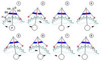
Riefler's free gravity escapement (function)

The escapement was patented in 1913 for the Clemens Riefler company. Sigmund Riefler had died a year earlier. He is not mentioned in the patent specification, but is said to have registered the invention as early as 1908.
It is a free escapement for pendulum clocks. The escapement ensures a largely interference-free oscillation of the oscillator.
The structure of the escapement can be seen in the diagram opposite. A pendulum P swings around the axis of rotation D. The axis of rotation is formed by a knife-edge bearing, consisting of two prisms PR attached to the frame G and the cutting edges SN (as with the Riefler spring-force escapement). In later versions, the cutting edges are mounted on flat agate plates and secured in position by two grain bearings located in the axis of rotation (see picture). A center punch bearing consists of an (adjustable) pin with a tapered point, which engages in a tapered socket with a larger taper angle. The two grain bearings have practically no influence on the free pendulum oscillation, since the entire pendulum weight is stored on the cutting edges and the disturbances caused by the grain bearing are negligible. The grain bearings can also be arranged with their axis at right angles to the pendulum axis of rotation if the cone tips lie on the axis of rotation and the opening angle of the cone socket is so large that the pendulum oscillation is not hindered.
Two independently movable lever arms HA also have an axis of rotation that coincides with D. The weight of the levers causes them to fall on the double escape wheel, which consists of the resting wheel RR and the lifting wheel HR, which are both mounted on a common shaft and driven by the drive. The arrangement of the toothing of the escapement wheels to one another results in a resulting contour RK (see picture), which is decisive for the interaction with the escapement elements. Only partial areas of the toothing of both wheels are effective, namely the inclined planes HF (lifting surfaces) and the stops RF (resting surfaces). Each lever arm is provided with a locking element H (pallet) engaging in both wheels, which is cylindrical in the area of the lifting wheel, while it is semicircular in the area of the resting wheel. A bar-shaped release pin AS is connected to an intermediate piece Z that is firmly inserted in the cutter holder SH, but can be rotated about the axis C for adjustment purposes if required, and extends as far as the two lever arms. The pendulum is attached to the intermediate piece. Each lever arm is provided with an actuating pin BS which can be adjusted by displacement in its longitudinal axis, against which the release pin can rest and, in the event of a pendulum movement, lift the lever arms from the double escapement wheel. With the adjusting arm JA, the intermediate piece and thus the release pin can be sensitively adjusted around the C axis using an adjusting screw JS. The adjustment options mentioned serve to balance the drive pulse and to set the engagement of the escapement elements in the escapement wheels.
The construction described can be varied in many ways in terms of design (e.g. cutting edge bearing with a flat counter surface, release pin above the axis of rotation D, use of only one escape wheel, etc.). However, the function described below is fundamental.
In phase 1 (see picture) the pendulum swings clockwise and is close to its central position. The retarding element on the input side, lifted by the release pin, has left the rest surface of the escape wheel. The retarding element on the output side accelerated the pendulum clockwise until it came into contact with the lifting surface. The escape wheel now turns and lifts the lever arm on the output side via the lifting surface until the retarding element has reached the resting surface (phase 2). Potential energy is thus supplied to the lever arm. This process has no effect on the pendulum (the actuation pin does not touch the release pin). It does not always have to take place in exactly the same time. Fluctuations in the drive torque therefore do not change the value of the energy supplied. The pendulum swings to its reversal point and when it swings back lifts the output-side inhibiting element from the resting surface. The release work to be performed should be very low (disturbance of the free oscillation). Therefore the resting areas are very small. The locking element on the input side has now again reached the height to which it was raised by the lifting surface during the previous rotation of the escapement wheel. The weight of the lever on the input side now accelerates the pendulum (actuation pin rests against the release pin) until the arresting element has reached the beginning of the lifting surface (phase 4). The potential energy that was supplied when the escape wheel was turned is transferred to the pendulum. This always has exactly the same value, as it only depends on the elevation and the unchangeable gravity. The pendulum now swings again to the point of reversal (phase 5), it is lifted (phase 6) and in phase 7 it is triggered again by the pendulum swinging back. Between phase 7 and phase 8, the lever on the output side now gives the pendulum the drive impulse, whereby the initial situation of phase 1 is reached again. In reality, the oscillation amplitude of the pendulum is much smaller than shown here for clarity (approx. 3 °).
The escapement was the most precise mechanical escapement ever designed, so it was used for astronomical precision clocks. With these watches, mean rate deviations of less than 0.01 s per day should have been achieved. From 1940, the Riefler company pendulum clocks were only manufactured with a gravity escapement. Production was stopped in the 1960s.
In contrast to the free spring locks by Riefler and Strasser, the gravity lock ensures a constant oscillation amplitude of the oscillator even when the torque of the drive changes. It can therefore be viewed as a constant impulse inhibition.
(see for this escapement also: intermediate lift )
Modern developments
With the mass production of quartz watches, there was no longer any need to improve mechanical escapements or to develop new ones in order to achieve a more accurate time display. However, high-quality mechanical wristwatches are enjoying increasing popularity and are being produced in increasing numbers again. In the case of wristwatches with manual winding, however, the power reserve also plays a role in addition to the accuracy. In addition to the classic Swiss lever escapement, new developments based on other principles as well as modern materials and manufacturing techniques are used. There are also corresponding efforts for pendulum clocks. Certainly, these escapements will not find wide application or become more important for time measurement technology. But they are very interesting from a technical point of view. Some of the concepts that have been put into practice are listed below.
Coaxial escapement ( Co-Axial escapement )

Coaxial escapement (principle)
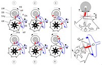
Coaxial escapement (function)

Animated coaxial escapement

The coaxial escapement is an escapement designed for small watches (wristwatches) with a balance-wheel-spiral oscillation system. The watch was developed by George Daniels in the 1970s and patented in 1980.
In this escapement, a lateral arm is added to the anchor, the end of which is essentially designed like the anchor of the Swiss anchor escapement.
The driving is not carried out by the jamming pallets. There are two more pallets for this. One of the two drive pallets is on the armature (between the jamming pallets), the other on the balance shaft (above the slot in the safety roll). The escape wheel consists of two differently sized, coaxially arranged gears. The release (release of the blocking pallet from the tooth) and the driving happens in favorable moments, namely in the middle position of the gear regulator, that is, in moments of its greatest kinetic energy. The drive pulse is alternately transferred from the small and large escape wheel to the drive pallets when driving. An uplift (movement on an inclined plane) does not take place.
The escapement has been mass-produced by Omega since 1999 . It has replaced the Swiss lever escapement and is used for all of the company's portable mechanical watches.
The principle of the escapement can be seen in the adjacent pictures (balance and armature safety knife not shown). The two escapement wheels (coaxial wheel KR) that are firmly connected to each other (and therefore move synchronously) are driven by the drive. The drive pallet TPA of the armature engages in the small escapement wheel, while the lower mounted drive pallet TPU attached to the double disk DS of the balance acts on the large wheel. The double disc is firmly connected to the balance shaft UW. Both HP jamming pallets (stops) work together with the large wheel. The armature A, which is movable about the axis DA, is limited in its movement by limiting pins BS. The lever block HS attached to the double disc engages in the fork of the anchor. In phase 1 the balance wheel swings clockwise and the lever block moves the armature, which loosens from the limiter pin. The escapement pallet on the output side leaves the escapement wheel tooth, whereby the release work has to be done by the balance. The balance drive pallet can move past the escape wheel tooth (very small distance). The escape wheel now turns and a tooth of the small wheel hits the drive pallet of the armature, so that it is moved and, via the fork, gives the lever stone and thus the balance wheel a drive impulse (phase 2). The relative movement s between tooth and drive pallet is very small (similar to the chronometer escapement), as this process takes place near the point of contact between the two circular paths (engagement area e).
This is an advantage compared to the Swiss lever escapement, where the tooth moves on the (mostly oiled) lifting surface (inclined plane). The friction conditions, which change over time, result in changes in the drive pulse and thus gear deviations.
In phase 3 the balance wheel swings to the point of reversal, the armature has touched the limiting pin and the escape wheel has moved until a tooth of the large escape wheel has touched the entry-side escapement pallet. The tooth of the small escape wheel has left the armature's range of impulses. The balance now swings back counterclockwise and does the release work on the blocking pallet on the entrance side (phase 4). The drive range of the balance is now given a drive impulse by the tooth of the large moving escape wheel (phase 5). The balance swings to its reversal point and a tooth on the escape wheel rests against the escape pallet on the output side. With the backswing phase 1 is reached again.
Constant pulse inhibition

Constant pulse inhibition
Constant impulse escapement IA Impulse anchor SA Tension anchor L Drive H Escapement wheel AZ Stop tooth SF Rise surface F Silicon spring U Balance S Spiral P Rotation axis of both anchors

The constant force escapement is designed for small watches with a mainspring drive and a balance-spring system. It was developed by Nicolas Déhon at Girard-Perregaux (patent application 2008; EP 2105806). The escapement ensures that drive pulses of constant magnitude are fed to the oscillation system, which leads to a constant oscillation amplitude of the balance and thus to high accuracy. The relaxed state of the tension spring has no (negative) influence on the drive pulses.
The escapement consists of two escapement wheels driven by a common impeller. You can therefore only move in the same direction and synchronously. The escape wheels are designed as cams with stop teeth. An anchor carries two anchor stones, which are alternately engaged with one of the two escapement wheels and has the usual anchor fork with safety knife. The armature is connected to an extremely thin rod spring made of silicon via two symmetrical cantilever arms. The bar spring is clamped in such a way that it has two S-shaped stable (mirror-image) states. It can be transferred from one to the other state ("break through") by a bending moment supplied by the armature via the extension arms. Energy is supplied to the spring up to the point of impact, which is released again when it is through. The energy released depends on the properties of the spring and is of constant magnitude.
When the lever stone of the balance wheel swings into the lever fork, the movement of the drive is blocked by an anchor stone resting against a stop tooth of an escape wheel. The silicon spring is tensioned by the armature until just before the point of breakdown. The balance wheel now has to do the (very small) release work by the lever stone slightly pivoting the armature, which on the one hand detaches the anchor stone from the stop tooth of the escape wheel and on the other hand causes the silicon spring to break through. The energy of the silicon spring delivered to the armature accelerates the armature and sends a drive impulse to the lever stone of the balance wheel via the fork. During this process, the drive is unlocked and can move until a stop tooth of the now other escape wheel comes into engagement with the corresponding anchor stone of the anchor. During this movement, the silicon spring is now tensioned in the opposite direction via a curve of the escape wheel until just before the breakdown point and the process described is repeated.
As long as the torque delivered by the drive to the escapement wheels is sufficient to tension the silicon spring, the drive impulse remains constant, so that the balance's optimal oscillation range is maintained even when the mainspring is relaxed.
To minimize the release work of the balance, it is useful to subdivide the armature into an impulse armature and a tension armature.
(see for this escapement also: intermediate lift )
Genequand inhibition
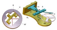
Genequand inhibition (components)

Gene quantum inhibition
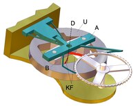
Gene quantum inhibition (structure)

Gene quantum inhibition (function)

Genequand inhibition (compensator)
This escapement was designed for wrist watches. It represents a miniaturized variant of the grasshopper inhibition using materials (silicon) and manufacturing processes (lithography, etching, lasers, etc.) of micromechanics. The joints (hinges) and rotating elements have been replaced by solid joints (spring joints). A modified balance wheel is used instead of a pendulum or balance. The patent was applied for in 2005, but watches with this escapement have so far (2016) not got beyond the prototype stage ( Vaucher Manufacture Fleurier ).
The escapement was developed by the Swiss physicist Pierre Genequand. It has low friction losses and therefore has a power reserve of more than 30 days. The oscillator (modified balance) works with an oscillation range of only approx. 5 ° (with the Swiss lever escapement it is approx. 220 °) and a frequency of 16 Hz (Schw. A. max. 4 Hz). Due to the silicon parts used, this escapement is not magnetic and does not require lubrication. The escapement consists of part A, which is attached to the board PL and made from one piece (see picture). It has the two grasshopper inhibiting elements H engaging in the escape wheel HR and the two springs F1. The latter allow a slight rotation (approximately) about the axis D (cf. FIG. 39 there). Part B is connected to the balance wheel U via a so-called cross-spring joint. This joint has the property that when part B is held, the balance can rotate (approximately) around the axis of intersection of the springs, whereby the springs exert a restoring force (analogous to the balance spring with other escapements). The crossing point is expediently on the central axis of the balance wheel. Part B can be permanently mounted on part A. The axis of rotation of the balance then coincides with axis D (see picture).
The function of the inhibition is the same as that of the grasshopper inhibition (see there). The picture shows how the balance, until then driven by the entry-side arresting element via part A and the universal spring joint, swings in a clockwise direction. The escapement element on the output side has come into engagement with the escapement wheel driven in clockwise direction by the drive and the balance wheel exerts a force on the escapement wheel via the universal spring joint together with the springs F1, which pushes it back a little. As a result, the spring action of the input-side inhibiting element can leave the tooth of the escape wheel and disengage. The escapement wheel now continues to move clockwise and the output-side retarding element exerts a torque on the balance wheel via A and the cross-spring element, which then turns part A by D and brings the input-side retarding element back into engagement with a following tooth.
The balance wheel equipped with the universal spring joint has the property that its period of oscillation depends heavily on the oscillation amplitude. Torque fluctuations in the drive lead to gear deviations. A so-called isochronism compensator is therefore provided. Via a mechanism that is not of interest here, the spring length L of two springs F2, which act on part A via pins ST, is changed with a slide S depending on the drive torque. The variable torque transmitted from the escapement wheel to the escapement elements and thus part A is always offset by a (variable) counter-torque generated by F1 and F2, which compensates for the fluctuations and guarantees the uniform oscillation range of the balance. This is shown schematically in the picture. Parts S, C and F3 (springs) are again made from one piece. S is led in C and held by F3. C is attached to the circuit board.
Haldimann inhibition

Haldimann inhibition

Haldimann escapement (detail)
It is an escapement for pendulum clocks. In the patent specification from 1999 reference is made to the road inhibition, but the spring force inhibition by Riefler can also be used for comparison. Both work with drive springs for the pendulum (see descriptions of the Riefler and Strasser spring escapement).
Traditional watchmaking assumed a so-called bending point (bending axis) for leaf springs for pendulum suspension or drive springs, the position of which should remain unchanged at around a third of the spring length. In reality, however, this point changes its position when the pendulum deflects (i.e. when the springs are bent), even if only minimally. With Strasser (pendulum suspended from a spring), the pendulum and mainspring move around different pivot points which move against each other during the pendulum oscillation and which also change their position relative to the fixed anchor pivot point. At Riefler, the pendulum or the armature is held in a knife-edge bearing so that the pivot point of the drive spring is shifted relative to the fixed pendulum or armature axis. The problem described is negligible for Riefler, since it occurs in an identically repeating form with every pendulum oscillation. Strasser, on the other hand, was forced to find a functioning but not very elegant solution for the transmission of power from the armature to the mainspring (steel point in perforated stone, later ball engagement). This is where the Haldimann inhibition comes in.
The power transmission from the armature to the drive springs is realized here by repelling permanent magnets. This supposedly simple solution is likely to have some pitfalls when it comes to implementation, since the adjustment of magnet systems is not trivial.
The function of the escapement can be seen in the adjacent picture. As with the Graham escapement, two retarding elements H (pallets) attached to armature A, which have stop surfaces RF (resting surfaces) and inclined planes HF (lifting surfaces), alternately engage in an escapement wheel HR driven by the drive. The pendulum P is suspended from the frame G via two pendulum springs PF. The two drive springs AF are also clamped on the pendulum and hold a magnet carrier MT at their other end (analogous to the flow inhibition; see there). Pendulum, magnet carrier (both approximately) and armature rotate around the axis D. Permanent magnets AM1, AM2 and PM polarized to repel are embedded in the armature fork AG and the magnet carrier. Armature shaft AW and escape wheel shaft HRW are, like two adjusting screws JS, mounted in the frame.
The pendulum swings counterclockwise. The two drive springs are relaxed (i.e. not bent). The anchor rests against an adjusting screw. The pendulum magnet PM approaches the armature magnet AM1. The closer the two magnets come, the greater their repulsive force (non-linear). This rotates the armature (the drive springs briefly bend slightly under the action of the repulsive force). The escape wheel releases from the exit pallet and rotates. The pendulum has to do the so-called release work because of the frictional force of the escape wheel tooth on the pallet. This represents a disturbance of the free pendulum oscillation and should be as small as possible (low engagement depth of the pallet in the escape wheel). One tooth of the escape wheel reaches the inclined plane of the pallet and thus accelerates the armature until it strikes the other adjusting screw. One tooth of the escape wheel comes to rest on the entrance pallet, so that its rotation is stopped. The escape wheel has twisted one tooth. During this rapid movement (the pendulum only moves slightly further) the armature magnet AM2 has approached the pendulum magnet and now uses the repulsive force to tension the drive springs, which give the pendulum a drive impulse in its direction of movement. The reason for this impulse is the rotation of the escape wheel, because it accelerated the armature by lifting the pallet and thus brought the magnets closer together. The pendulum swings up to its reversal point, whereby it is braked by the approach of the pendulum magnet to the armature magnet AM1 (tension of the drive springs in the opposite direction). After the pendulum has come close to its central position again (drive springs relaxed), the pendulum magnet and armature magnet AM2 are so close that the triggering on the input pallet and then the drive pulse takes place in a clockwise direction.
It is not known whether watches were built with this escapement and which rate results were achieved.
See also
- Gear regulator for constant sequence (brake regulator): Simple mechanical timers often do not work with inhibitions (inhibitor regulators), but use friction brakes (e.g. centrifugal brake regulators in gramophones , telephone dials ) or aerodynamic brakes ( e.g. windscreen in the striking mechanism of a clock or in a music box ) .
- Isochronism
- Technology in the Renaissance
literature
- Urban Jürgensen: General principles of precise time measurement using clocks or a summary of the principles of clock making for the most careful time measurement . - Leipzig, publisher by Ludwig Schumann, 1840.
- Bassermann-Jordan, Bertele: clocks . Klinkhardt & Biermann publishing house, Braunschweig 1969.
- GO Weiland, Ballwey (ed.): Bruckmann's watch lexicon . Verlag Bruckmann, Munich 1980, ISBN 3-7654-1825-0 .
- Rudi Koch (Hrsg.): BI-Lexicon - clocks and time measurement . Verlag VEB Bibliographisches Institut, Leipzig 1989, ISBN 3-323-00100-1 .
- Helmut Kahlert , Richard Mühe , Gisbert L. Brunner : Wristwatches: 100 years of development history. Callwey, Munich 1983; 5th edition ibid 1996, ISBN 3-7667-1241-1 , pp. 52 f., 58 f. and 505 f.
- Gerhard Claußen & Karl-Hermann Ströde: The Great Clock ABC, Vol . 1 . Verlag Ebner, 1999, ISBN 3-9803675-0-9 .
- Klaus Menny: The clock and its mechanics . Verlag Schäfer, Hannover 2003, ISBN 3-87870-687-1
- Charles-Andre Reymondin, Georges Monnier, Didier Jeanneret, Umberto Peraratti: Theory of watchmaking. Publisher: FET (Federation des Ecoles Techniques) 2001, ISBN 2-940025-11-8 (German), ISBN 2-940025-10-X (French), ISBN 2-940025-12-6 (English)
Individual evidence
Attention! With DEPATISnet information, an error message often appears the first time it is clicked. The second time the link works.
- ↑ Technical terms when mentioned for the first time in italics and in brackets, mostly from Klaus Menny: Die Funktion der Uhr , Callwey, 1994
- ^ Klaus Menny: The function of the clock. Callwey, Munich 1994, ISBN 3-7667-1095-8 , p. 37ff.
- ^ Klaus Menny: The function of the clock. Callwey, Munich 1994, ISBN 3-7667-1095-8 . Pp. 37-40.
- ↑ John Harrison: The principles of Mr. Harrison's timekeeper, with plates of the same . W. Richardson, January 1, 1767 ( Google Books [accessed June 1, 2016]).
- ↑ Jonathan Hird, Jonathan Betts, Derek Pratt: The Diamond Pallets of John Harrison's Fourth Longitude Timekeeper — H4 . Annals of Science. tape 65 , No. 2, April 1, 2008.
- ↑ H.Jendritzki: writings of the Friends of old clocks . Vol XVII. German Society for Chronometry, Nuremberg 1985.
- ↑ Krug u. a .: BI lexicon clocks and time measurement . Ed .: Rudi Koch. Bibliographisches Institut, Leipzig 1989, ISBN 978-3-323-00100-8 .
- ↑ 300th Anniversary of the Longitude Act. Archived from the original on June 11, 2016 ; accessed on June 11, 2016 .
- ^ Museum landscape Hessen Kassel. In: www.museum-kassel.de. Archived from the original on May 27, 2016 ; accessed on May 27, 2016 .
- ↑ Ken Kuo: Cross-Beat Escapement (or Double Balance Escapement). December 25, 2013, accessed September 2, 2016 .
- ^ Richard Mühe: The historical clock collection Furtwangen . Furtwangen 1967.
- ↑ Volker Vyskocil: Black Forest hook escapement . UhrenTechnik, accessed on August 30, 2013 (animated).
- ↑ Gooii Ltd. [email protected]: H1 - National Maritime Museum. Retrieved February 14, 2017 .
- ↑ Marlene Halliday: Harrison Clock - H1. July 14, 2009. Retrieved February 16, 2017 .
- ^ Valentin: Physics of Harrison's H1 clock. In: The Sugar High. October 13, 2012, accessed February 14, 2017 .
- ↑ Ruxu you, Longhan Xie: The Mechanics of Mechanical Watches and Clocks . Springer Science & Business Media, 2012, ISBN 978-3-642-29308-5 ( Google Books [accessed June 11, 2016]).
- ↑ bshallard: Grasshopper escapement. May 3, 2007, accessed June 11, 2016 .
- ↑ Volker Vyskocil: Graham escapement. UhrenTechnik, accessed on August 30, 2013 (animated).
- ↑ Fritz von Osterhausen: Callweys lexicon. Munich 1999, ISBN 3-7667-1353-1 , p. 125
- ↑ Theory of watchmaking. CADEV, Lausanne 2001, ISBN 2-940025-11-8 , p. 312.
- ↑ Volker Vyskocil: cylinder escapement . UhrenTechnik, accessed on August 30, 2013 (animated).
- ^ Helmut Kahlert , Richard Mühe , Gisbert L. Brunner : Wristwatches: 100 years of development history. Callwey, Munich 1983; 5th edition ibid 1996, ISBN 3-7667-1241-1 , pp. 59 and 506.
- ↑ Fritz von Osterhausen: Callweys lexicon. Munich 1999, ISBN 3-7667-1353-1 , p. 369f
- ^ Helmut Kahlert, Richard Mühe, Gisbert L. Brunner, Christian Pfeiffer-Belli: wrist watches: 100 years of development history. 1996, p. 506.
- ^ Helmut Kahlert , Richard Mühe , Gisbert L. Brunner : Wristwatches: 100 years of development history. Callwey, Munich 1983; 5th edition ibid 1996, ISBN 3-7667-1241-1 , pp. 59 and 506.
- ↑ Volker Vyskocil: Duplex escapement . UhrenTechnik, accessed on August 30, 2013 (animated).
- ↑ GA Berner: Illustrated specialist lexicon of watchmaking , keyword Dutertre . Electronic version. Retrieved February 17, 2013.
- ^ Klaus Menny: The function of the clock. Callwey, 1994, pp. 42-43.
- ↑ Krug u. a .: BI Lexicon Clocks and Time Measurement . Ed .: Rudi Koch. Bibliographisches Institut, Leipzig 1989, ISBN 978-3-323-00100-8 .
- ↑ Ruxu you, Longhan Xie: The Mechanics of Mechanical Watches and Clocks . Springer Science & Business Media, 2012, ISBN 978-3-642-29307-8 ( Google Books [accessed July 5, 2016]).
- ↑ Moritz Großmann: The free anchor passage for clocks. Retrieved July 5, 2016 .
- ↑ Volker Vyskocil: Glashütte anchor passage. UhrenTechnik, accessed on August 30, 2013 (animated).
- ↑ Lexicon - watch manufacturers and movements from Glashuette. In: www.glashuetteuhren.de. Retrieved July 2, 2016 .
- ↑ A. Preslmayer: Templates for the watchmaker's technical drawing. Retrieved June 2, 2016 .
- ↑ Volker Vyskocil: Swiss lever escapement. UhrenTechnik, accessed on August 30, 2013 (animated).
- ^ Helmut Kahlert , Richard Mühe , Gisbert L. Brunner , Christian Pfeiffer-Belli: wrist watches: 100 years of development history. Callwey, Munich 1983; 5th edition, ibid 1996, ISBN 3-7667-1241-1 , p. 505.
- ^ Zdenek Martinek, Jaroslav Rehor: Mechanical watches . VEB Verlag Technik Berlin, ISBN 3-341-00022-4 .
- ↑ Sinn watches: DIAPAL. In: www.sinn.de. Retrieved July 2, 2016 .
- ↑ Theory of watchmaking. CADEV, Lausanne 2001, ISBN 2-940025-11-8 , pp. 101-122.
- ↑ Volker Vyskocil: pin anchor passage . UhrenTechnik, accessed on August 30, 2013 (animated).
- ↑ Helmut Kahlert u. a .: wristwatches. 100 years of development history. 1996, p. 505.
- ↑ Klaus Menny: The clock and its mechanics: for collectors and enthusiasts . HolzWerken, 2003, ISBN 978-3-87870-687-8 ( Google Books [accessed July 5, 2016]).
- ↑ Zdenek Martinek; Jaroslav Rehor: Mechanical watches . VEB Verlag Technik Berlin, ISBN 3-341-00022-4 .
- ↑ Helmut Kahlert u. a .: wristwatches. 100 years of development history. 1996, p. 506.
- ↑ Fritz von Osterhausen: Callweys lexicon. Munich 1999, ISBN 3-7667-1353-1 , p. 55
- ↑ Rudi Koch u. a .: BI lexicon clocks and time measurement . Ed .: Rudi Koch. VEB Bibliographisches Institut Leipzig, ISBN 3-323-00100-1 .
- ↑ Volker Vyskocil: Chronometer escapement with spring. UhrenTechnik, accessed on August 30, 2013 (animated).
- ↑ Volker Vyskocil: Chronometer escapement with rocker. UhrenTechnik, accessed on August 30, 2013 (animated).
- ↑ Curt Dietzschold: The tower clocks, including the so-called art clocks. ; Bernhard Friedrich Voigt; Weimar 1894; P. 99 ff.
- ↑ The Gravity Escapement. In: www.bmumford.com. Retrieved July 14, 2016 .
- ↑ Double wheel escapement for chronometers with completely free balance and for pendulum clocks with free pendulum. Retrieved June 20, 2016 .
- ↑ Dieter Riefler: Riefler precision clocks: 1890-1965 ; Callwey Verlag; Munich 1991; ISBN 3-7667-1003-6 .
- ↑ Escapement with absolutely free balance for all types of chronometers, including pocket watches. In: depatisnet.dpma.de. Retrieved June 20, 2016 .
- ^ Jürgen Ermert: Precision pendulum clocks. Retrieved June 16, 2019 .
- ↑ Sigmund scoring Jewelers precision pendulum clocks - German Clock Museum. In: www.deutsches-uhrenmuseum.de. Retrieved June 19, 2016 .
- ^ Wilhelm Schultz: L. Strasser's free escapement for precision pendulum clocks. In: Deutsche Uhrmacher-Zeitung (1900), No. 17, pp. 19-21.
- ↑ Jendritzki: From the road inhibition. (PDF) Retrieved June 11, 2016 .
- ↑ Strasser & Rohde from 1875–1917 - watch manufacturers and movements from Glashuette. In: www.glashuetteuhren.de. Retrieved June 11, 2016 .
- ↑ Gravity escapement with two drive levers. In: depatisnet.dpma.de. Retrieved June 20, 2016 .
- ↑ The genius Dr. phil. hc. Sigmund Riefler. (PDF) Retrieved June 20, 2016 .
- ↑ George Daniels: Watches, clocks an chronometers and escapements therefor. Retrieved June 25, 1016 .
- ↑ Volker Vyskocil: "Extra Flat Co-Axial" escapement. UhrenTechnik, accessed on August 30, 2013 (animated).
- ↑ DEPATISnet document DE602005005465T2. In: depatisnet.dpma.de. Retrieved July 17, 2016 .
- ↑ CSEMtechnologies: Innovation in the watch market: This watch is only wound once a month. September 15, 2014, accessed July 20, 2016 .
- ↑ Smooth revolution. June 3, 2016. Retrieved July 20, 2016 .
- ↑ DEPATISnet document US020140363217A1. In: depatisnet.dpma.de. Retrieved July 27, 2016 .
- ↑ DEPATISnet document US020150234354A1. In: depatisnet.dpma.de. Retrieved July 27, 2016 .
- ↑ DEPATISnet document US000008672536B2. In: depatisnet.dpma.de. Retrieved July 27, 2016 .
- ↑ DEPATISnet | Document CH000000690046A. In: depatisnet.dpma.de. Retrieved July 20, 2016 .
- ^ Siegfried Hildebrand : Feinmechanische Bauelemente. Carl Hanser, 1968, pp. 773-785.
Web links
- Volker Vyskocil: Inhibitions . UhrenTechnik, accessed on August 30, 2013 .
- Inhibition. Watch Wiki, accessed August 8, 2013 .