
Telecommunication connection unit
The telecommunications connection unit ( TAE ) is a connection technology for end devices in telecommunications technology . In Germany and partly also in Liechtenstein and Luxembourg , TAE is used as a junction box for analog telephone connections ( a / b interface ) and ISDN connections for connecting the NTBA to the connection line.
TAE are also used in private telephone systems.

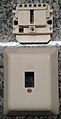
TAE type NFF flush-mounted

Type NFF without cover

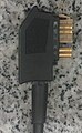
TAE plug
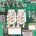
Individual TAE sockets in print assembly in a VoIP- enabled DSL router


The TAE was introduced in Germany in 1987 in preparation for the postal reform and the liberalization of the terminal equipment market on July 1, 1989. Since then, the user has been able to connect approved telephones and additional devices (answering machine, fax, modem) himself. The forerunner was the junction box (VDo, SvDo) with a fixed telephone connection. For additional equipment was a junction box (ADo) retrofitted as a pluggable connection.
First TAE as a network termination

The so-called 1st TAE (also monopoly socket ) is the first connection socket (from the point of view of the network operator) in the subscriber's premises and fulfills special tasks. It contains an invisible passive test termination (PPA) for measurement purposes and serves as a network termination . Therefore it must not be replaced by a normal TAE socket or a DSL splitter .
The 1st TAE is a special NFN socket (surface-mounted or flush-mounted) with the label " 1. " and a typical, beaded design. The connection is made using insulation displacement technology (LSA).
By mid-1994, the 1st TAE standard boxes were installed, to which a passive test termination (visible under the cover) was clamped and a telecom sticker was attached.
A line test is possible with IP-based telephony via a so-called signature cable between the TAE socket and the modem.
Occupancy

| 1 | 2 | (3) | (4) | 5 | 6th |
|---|---|---|---|---|---|
| La | Lb | (W) | (E) | b2 | a2 |
| 1 | 2 | 1' | 2 ' | 3 | 3 ' | 5 | 6th |
|---|---|---|---|---|---|---|---|
| La | Lb | La | Lb | W. | W. | b2 | a2 |
TAE sockets are made 6-pin and (rarely) 4-pin. In the 4-pole version, terminals 3 and 4 (W wire and earth) are saved because they are superfluous with today's end devices. The plug connections are compatible.
In the national ISDN (1TR6) of Deutsche Telekom (installed until 1994) 8-pin TAE sockets were used for the S 0 bus. An ISDN telephone with an 8-pin TAE plug does not work in today's Euro-ISDN.
| Clamp | meaning | Wire color | ||||
|---|---|---|---|---|---|---|
| At the plug | At the connection terminal *) , according to VDE 0815, when using the 1st twin wire | |||||
| DIN 47100 (LiYY) |
Americ. Color code | stranded in bundles, e.g. B. J-YY, J-2Y (St) Y |
stranded in layers, e.g. B. JY (St) Y |
|||
| 1 | La | a-wire ( a / b interface ) |
White | red | red | red |
| 2 | Lb | b-core | brown | green |
red with 1 ring (Distance 17 mm) |
black (2 × 2) blue (from 3 × 2) |
| 1' | La | Looped a-wire ( a / b interface ), connection for second alarm clock |
||||
| 2 ' | Lb | Looped b-wire, connection for second alarm clock | ||||
| 3 | W. | a-wire for second alarm clock ( second ring tone device ), no longer used today | green | |||
| 3 ' | W. | Connection for second alarm clock, no longer used today | ||||
| 4th | E. | Earth for outside line of the extension and DEV , no longer used today | yellow | |||
| 5 | b2 | Looped b-core (inserted F connector switches off b2) | Gray | yellow | ||
| 6th | a2 | Looped a-wire (inserted F- connector switches off a2) | pink | black | ||
*) The wire color when wiring TAE sockets depends on the cable laid and the pair of wires used in it. See also telephone cables and telephone connection cables .
Coding


TAE plugs and sockets each have either an F -, N or Z - coding .
- The F stands for F ernsprechen and is designed for phones provided. NTBA or DSL splitters are also plugged into the F socket.
- The encoding N stands for n maybe telephony (colloquially N just falls) and thus for all devices other than telephones, and include, for example, answering machines , fax machines , modems and fees Gazette , but also for. B. Telephone-fax combination devices.
- The code Z stands for additional devices and was used for serial data interfaces (modem, also on leased lines).
- To telephone systems and terminal adapters , there are occasionally U -encoded sockets ( " u niversal"), in which one optionally an N - or F may introduce plug, however, is contrary to the sense of the TAE principle.
- E- coded sockets with staggered cutouts look similar but have nothing to do with telephone connections. They can be found on Ethernet connection sockets (EAD) that were developed from the TAE system.
Executions
| execution | description | |
|---|---|---|
| F. | 1 socket | for F ernsprechen (eg telephone) |
| N | 1 socket | for n maybe telephony (for example, voice mail, modem, fax, dialer) |
| NF | 2 sockets | for two associated N and F devices |
| FF | 2 sockets | Two a / b connections for two independently wired F devices |
| NF / F | 3 sockets | Two a / b connections, for two independently wired F devices, an N socket is connected in front of the middle (F) socket |
| NFN | 3 sockets | Most common variant. Both N sockets are connected in front of the middle socket (F). |
| Z | 1 socket | not in use today, it is used to connect serial data interfaces. |
| Z / F | 2 sockets | not in use today, it is used to connect serial data interfaces and a galvanically isolated telephone to two terminal blocks. |
| HS / F | 1 socket | Not in use today, it is used to connect a telephone as the last socket in a socket system with a hold circuit in order to be able to plug a telephone during a phone call and to be able to continue the call at another socket in the same system. |
| IAE / TAE | Newer composite can. For example for ISDN / analog or DSL / analog applications. Wired independently of each other. | |
| U | not coded for u niversal use | |
| D. | 1 socket | same as N-coding, for data set 756D |
Several devices on a TAE
Depending on the use and the corresponding switching of the communication terminal, several devices connected to an NFN socket can either be used simultaneously, but dependent on one another, or only one device can be used at the same time.
Simultaneous use is given, for example, when connecting an answering machine and a telephone. Technically speaking, the answering machine is looped in in front of the telephone.
This means that a call accepted by the answering machine can be taken over by lifting the telephone receiver; the recording of the call by the answering machine is ended.
It is similar when connecting an answering machine, fax machine and telephone to an NFN socket. Here fax machine and answering machine are looped in in front of the telephone. If the fax machine has a passive fax switch and the two communication terminals are plugged in in the correct order, the incoming faxes will be answered by the answering machine, but the fax signals will still be received by the fax machine and the answering machine will not record them at all.
Separate use, however, is given when connecting a modem and a telephone to an NFN socket. For example, if a modem plugged into the left N socket is activated, it disconnects the devices behind it from the line, the right N socket and the F socket are then switched off.
The above also applies to the left and middle socket of an NF / F socket ; an answering machine (N socket) can be interrupted by the telephone (middle F socket); a modem (N socket) can switch off the telephone (middle F socket). The right F socket, however, is electrically independent of the other two sockets.
Two devices connected to one FF socket do not interfere, here too both slots are independent of each other.
Without an inserted plug, the contact tongues in the socket lie against one another in pairs. This means that there is electrical contact between connections 1 and 6 and between connections 2 and 5. In this way, with the common NFN socket, the connection line that first arrives at the left N socket is switched through to the right N socket and from there to the F socket in the middle. The internal technical interconnection of an NFN socket therefore differs from the plan view.
When a plug is inserted into one of the sockets, the contact tongues are pushed apart by the plug and at the same time the device concerned is looped into the connection line. In order for this to work properly, the connection cable of an N device must have four wires and be connected. In the inactive state, the device in question must bridge the outward and reverse direction, which is usually done by relay . Only then is another device connected to the connection line in a socket connected downstream. The use of an automatic changeover switch ( AMS , formerly AWADo ) can help here, for example .
As an alternative, inexpensive devices often use two wire bridges in the TAE plug, which lead the interrupted connection line through in the plug. This contradicts the meaning of the TAE principle, but it is an increasingly common procedure.
Modems
With older modems (usually with ZZF / BZT / BAPT approval number) the connection line was bridged by means of a relay when inactive. You could hear this relay picking up (interruption of the connection line) when dialing in such a device.
With newer modems according to the European approval standard CTR21 (including all those built into notebooks) this relay is saved and they are only connected with two poles. In order for such a modem as an N device not to switch off the telephone behind it, a special bridged modem cable is required in which the interrupted line is bridged by two wire bridges in the TAE-N connector. Disadvantage: The parallel connected end devices, such as a telephone, can lead to disruptions or interruptions in the transmission due to the stub lines generated . This can be remedied by an automatic multiple switch (AMS, T2 / T3 switch, formerly AWaDo) or, as an emergency solution, a manual limitation of the modem connection speed using special, mostly poorly documented AT configuration commands .
Advantages and disadvantages

In contrast to the RJ-XX plug connection common in some countries , TAE sockets have integrated openers, which are made up of two pairs of opposing contact springs. This enables mechanical switching tasks that, when the plug is not inserted, connect a subsequent connection device to the network.
The NC contacts of the N sockets are connected upstream of the F socket. They can oxidize or become dirty through penetration of moisture, wall paint etc. and cause contact problems (noise and crackling) up to total failure.
The "RJ-XX" plugs ( Registered Jack ) ( UAE connection sockets) commonly used on ISDN devices in the USA generally for telephone connections and in the USA have no normally closed contacts and in this regard offer greater reliability.
Compared to the RJ-XX plug connection, the mechanical parts of the TAE plug connection are larger, but also made more stable. With RJ plugs, the catch often breaks off.
Norms and standards

The TAE connection is standardized in DIN 41715. However, the pin assignment of the RJ-11 connector on the other side of the cable is not uniform. The TAE plug can therefore have a different pin assignment if the TAE cable is not connected to the device via an RJ-11 plug. The use of an incompatible cable can lead to corresponding malfunctions. For historical reasons, older devices from Siemens, Telekom and from abroad have different RJ-11 assignments. There are suitable adapter sets on the market (see illustration) or TAE-RJ-11 cables with suitable connections.
TAE 8, TAE 8 + 4, TAE 16
The above-mentioned TAE 6 were supplemented by the TAE 8, the extended TAE 8 + 4 and the TAE 16. The TAE 8 (8 contacts) and the TAE 8 + 4 (12 contacts) were introduced for the S 0 bus to connect the ISDN terminals of the national ISDN (protocol variant FTZ 1 TR 6). The TAE 16 already existed as ADo 16 , it was simply renamed; it was used to connect analogue end devices that require more wires (16 maximum).
TAE 8

TAE 8 + 4
TAE 8 + 4 plug

TAE 16

TAE 16 plug


The TAE 8, TAE 8 + 4 and TAE 16 are no longer used.
See also
-
Telephone socket
- the Austrian telephone socket (TDO)
- the Reichle plug (and the corresponding T + T83 socket, Switzerland)
- RJ-XX - Western plug (US standard)
- Universal connection unit ( RJ-XX )
- Termination point line technique
literature
- Jürgen Lopez: The telecommunication connection unit (PDF; 1 MB) In: Deutsche Telekom AG (Hrsg.): Instruction sheets. Vol. 48, 7/1995, pp. 422-427
- ZVEI , BITKOM (Ed.): Forum 10 - Installation of terminal equipment in telecommunications (PDF; 2.2 MB) 6th edition, ZVEI, Frankfurt / Main and BITKOM, Berlin, May 2011
- Hans Joachim Geist: Large practical book of communication technology. 1st edition, Elektor-Verlag, Aachen, 2001, ISBN 3-89576-109-5
Individual evidence
- ↑ Deutsche Telekom instruction sheets. July 1995, p. 422.
- ↑ Wolfgang P. Riegelmayer: Wiring Concepts. Basics and practice. 1st edition, Vogel Buchverlag, Würzburg 1995, ISBN 3-8023-1539-1 , p. 175.
- ^ Mathias Herbers: TAE doses - telefonanleitungen.de. Retrieved February 1, 2018 .
- ^ ISDN - Die Technik, Andreas Kanbach & Andreas Körber, Hüthig, 2nd edition, 1991, p. 111ff