
UTM coordinate system

The UTM system (from English Universal Transverse Mercator ) is a global coordinate system. It divides the earth's surface (from 80 ° south to 84 ° north) in strips into 6 ° wide vertical zones, which are individually leveled with the most favorable transverse Mercator projection and covered with a Cartesian coordinate system .
The universal polar stereographic projection ( UPS ) is used to depict the polar ice caps .
Both in Germany and Austria, UTM coordinates are increasingly used with reference to the ETRS89 reference system with the GRS80 ellipsoid . These are also increasingly being used in land surveying in other countries. The Gauß-Krüger coordinate system , which is related to UTM, will thus lose its importance in the long term.
Military geographic institutes now exclusively use the Military Grid Reference System , in the German-speaking area also UTM reference system, short form UTMREF, a grid square- oriented geographic reporting system based on the UTM coordinate system.
history
One form of the UTM coordinate system was developed around 1942/1943 for the German Wehrmacht . It probably took place in the aerial photography and surveying department in the Reich Aviation Ministry . In 2014, maps from 1944 were found in the Bundesarchiv-Militärarchiv , which were created on the basis of the UTM projection and are labeled UTMREF . From 1947 onwards, the United States Armed Forces used a standard based on this. In the context of internationalization, it is intended to replace the individual national coordinate systems in the long term. In the official German topographic maps, the Gauß-Krüger coordinate system is increasingly being replaced by the UTM system based on the reference ellipsoid WGS84 .
The A rbeitsgemeinschaft d he V ermessungsverwaltungen the States of the Federal Republic of Germany (AdV) has in 1991 the introduction of ETRS89 which the WGS84 - date corresponds decided as a uniform official position reference system for the whole of Germany. For the epoch January 1, 1989, the coordinates from ETRS89 and WGS84 were less than a meter apart, which means that both systems can be regarded as identical within this positional accuracy. Furthermore, the AdV decided in 1995 to introduce the UTM system in connection with the ETRS89 date across the board. This means that all surveying administrations in Germany are now obliged to also transfer the real estate cadastre to the UTM / ETRS89. The Federal Agency for Cartography and Geodesy (BKG) provides the geographic information required for this in high accuracy via the geodata center . Today, the UTM / ETRS89 system in Germany is implemented by SAPOS , the satellite positioning service of the German national surveying service, with high precision, homogeneous and area-wide for all areas of surveying.
In Austria, too, the current federal notification procedure , as used by the authorities and aid organizations, is gradually being replaced by the UTM coordinate system. More and more new maps on paper (e.g. Auto Atlas) have drawn in this coordinate system, just as today's GPS navigation devices already have the UTM system based on WGS84 as an application standard.
construction
UTM uses a transverse Mercator projection . In contrast to the conventional Mercator projection, the projection cylinder does not touch the surface, but cuts it so that a strip-shaped part of the globe protrudes from the cylinder surface. This shortens the meridian in the middle between the penetration circles in the projection by a factor of 0.9996. Apart from that, it is reproduced undistorted.
Since the transverse Mercator projection on which the UTM projection is based strongly distorts areas that are far from the cutting line (see images below), UTM does not use a single projection to cover the entire surface of the earth, but divides the earth into 6 ° widths so-called zones . The middle meridian of the zone is then used as the reference meridian for the projection. For example, Zone 31 extends from 0 ° to 6 ° East. The reference meridian lies in the middle at 3 ° east.
The penetration circles are 360 km apart in the UTM projection, which corresponds to an angular distance of approx. 3 ° at the equator. Therefore, at low latitudes, the zone is wider than the cutting line. The areas outside of the penetration circles are stretched during projection, while inside they are slightly compressed.
It is important to distinguish between the constant 360 km wide cutting strips and the constant 6 ° wide zones. A zone defines a (curved) area in which a particular projection is to be used. This projection creates a planar image of the entire earth, which is covered with a Cartesian coordinate system or a grid. However, these coordinates are only used within the associated zone. Together, the strip cut zone and reference meridian and the Equator, (then the after projection into the plane as the axis of ordinate means Meridian called) or serve abscissa axis.
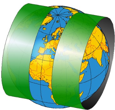
UTM cylinder projection, excessive stripe width (it is only 360 km)

Transverse Mercator projection for the prime meridian

Transverse Mercator projection for 45 ° E


Zoning
The earth is divided into zones 6 degrees wide between 180 degrees west and 180 degrees east. The reference meridians 3 °, 9 °, 15 °,… 177 ° run in the middle of the 60 zones formed in this way.
The zones are numbered from west to east. The zone from 180 ° to 174 ° west longitude receives the code number 1. The one from 174 ° to 168 ° the code number 2 etc. The German-speaking area is mostly in zones 32 (6 ° to 12 ° east longitude) and 33 (12 ° up to 18 ° E).
Zone fields according to UTMREF
The division into zone fields or a comprehensive grid is not part of the actual UTM system. See, for example, publications by the AdV and the NPS . This division is an extension and leads to the UTMREF system:
The zones are divided from 80th latitude south to 84th latitude north by circles of latitude at a distance of 8 ° into zone fields, which are labeled with letters. The southernmost zone field line has the letter C and the northernmost the letter X; only this northern edge line X is slightly higher at 12 °. The letters I and O are omitted to avoid confusion with the digits 1 and 0.
Only in Scandinavia there are fields with different latitudes (i.e. west-east extension): The zone field 32V is widened by 3 ° to 9 ° in the west, so that southern Norway only needs this zone field. The neighboring field 31V is correspondingly narrower here. At the northern edge of the strip zone belt (in the field row X, at 72 ° - 84 ° north) 4 widened zone fields (31X, 33X, 35X, 37X) with 9 °, 12 °, 12 ° and 9 ° latitude cover the area from the prime meridian to 42 ° East, which is regularly divided into 7 zone strips of 6 ° to the south. The right (east) value of locations in these 6 zone fields with a change in width is determined from the meridian (+500 km offset) that also serves as the central meridian in the zones with the same number and 6 ° standard width.
The North Pole and South Pole regions are mapped with their own map projection, the Universal Polar Stereographic Projection . The south pole region, anything more than 80 degrees south latitude, is divided into zones A (0 and 180 degrees west longitude) and B (0 to 180 degrees east longitude). The North Pole region, anything further north than 84 ° north latitude, is divided into Zones Y (western longitude) and Z (eastern longitude). No code numbers are used here, but the letter code of the zone fields is continued.
- The division of some continents into UTM zones

Europe
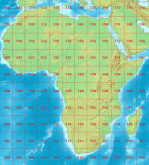
Africa

South America


Coordinates
In order to get to the coordinates of a point within a zone, the UTM projection belonging to the zone is used as described above in order to map the globe over the contacting cylinder and its rolling into the plane. The (projected) equator now forms the X-axis, the central meridian the Y-axis. The X and Y axes are perpendicular to one another and the X and Y values are read off as in a Cartesian coordinate system , i.e. parallel to the axes and not to the lines of longitude and latitude that are now curved. The use of the X-axis for the eastward value and the Y-axis for the high value is common in geographic information systems and also corresponds to the definition by the Working Group of the Surveying Administrations of the Federal Republic of Germany ( AdV ). In geodesy , the opposite interpretation of the coordinate axes is used.
Only on the central meridian does the Y-axis ( grid north ) coincide with geographic north . It is not the same as true north at coordinates away from the central meridian. Therefore, many maps based on the UTM system draw the difference between grid north and geographic north, the so-called meridian convergence , on the Y-axis. This makes orientation easier with the help of magnetic and gyro compasses or with the help of the stars .
By definition, the X value of the central meridian is set to 500,000 meters (“ false easting ”). This avoids the negative values west of the central meridian that would arise if the X value of the central meridian were 0 m. All permissible legal values are between 100,000 and 899,999 meters, so they are always six digits. Since the Y-values would also be negative in the southern hemisphere, the equator is set there by definition to the Y-value 10,000,000 m and thus also receives positive values. In the northern hemisphere, the equator has a Y value of 0 m.
The X and Y values are given in meters . The X (right) value is the distance to the central meridian, from the Y (high) value the distance to the equator can be calculated.
The X-value obtained in this way must be multiplied by the scale factor, which is a constant 0.9996 (this factor does not include other line distortions of the projection). This is how the easting of the UTM coordinate is obtained. The northing value is the Y value multiplied by the scale factor. It is important to specify the corresponding zone number, as otherwise the coordinate is ambiguous.
The Military Grid Reference System ( MGRS ) or UTM Reference System ( UTMREF) also divides the zones into squares measuring 100 km × 100 km parallel to the central meridian, regardless of the zone fields. The grid fields are given pairs of letters as names and are also used to limit coordinates.
If an area is to be worked on that extends over several zones, the coordinate system of a zone can also be used beyond the zone boundaries, provided that the increasing distortions still allow sensible use.
Coordinate example

-
Paradeplatz (Mannheim)
- Geographical coordinates in degrees according to WGS84
- 49 ° 29 '13.6 "N.
- 8 ° 27 '58.6 "E.
- UTM coordinates (WGS84)
- Zone 32-North (grid square 32U, irrelevant for the calculation of the numerical values)
- East / East 461344
- North value / high value 5481745
- this results in the geo-reference 32 N 461344 5481745
- The usual spelling is 32U 461344 5481745 ('U' stands for the Latitude Band of the corresponding UTM zone field)
- UTMREF / MGRS coordinate with grid
fields
- Zone 32U
- Grid square MV
- East / East 61344
- North value / high value 81745
- the complete georeference is therefore 32UMV 61344 81745
- Geographical coordinates in degrees according to WGS84
application
The UTM coordinate system or the UTM reference system is used in the armed forces , in disaster control , the fire brigade , the rescue service , the police and other aid organizations as well as in surveying . The UTM coordinate system is always used for courses on the topic of map studies . In Germany , such precise communication is e.g. B. possible between fire brigade and a rescue helicopter. Other private applications (e.g. gliding, geocaching, etc.) are provided with UTM cards on CD, which are available in stores under the collective term Top50 for Germany, Austria and Switzerland (DA-CH). Also, Google Maps and Google Earth are adjustable to the UTM coordinate system in the world and can z. They can be used, for example, for application-oriented GPS navigation devices in the oil and gas search if more precise maps are missing.
In Germany, the Land Surveying Offices made the transition to the UTM system with reference to the ETRS89 (system) with the GRS80 ellipsoid from the 1990s . In mid-2015, Saxony was one of the last federal states in which the changeover was carried out.
The UTM / MGRS coordinates are determined and transferred to topographic maps using a map pointer that is appropriate to the map scale .
Differences to the Gauss-Krüger system
The UTM coordinate system is similar to the Gauß-Krüger coordinate system . Both are a conformal mapping of the earth's ellipsoid into the plane and can be calculated using the same mapping equations. The main difference is that Gauß-Krüger coordinates in Germany refer to the Bessel or Krassowski ellipsoid and usually use 3 ° wide meridian strips, while UTM coordinates refer to the WGS84 or GRS80 ellipsoid and use 6 ° wide zones .
With this conformal type of imaging, the line distortions at the outer edge of the stripes increase considerably as the stripe width increases. To compensate for the stronger image distortions (enlargements) at the zone edges caused by the wider meridian strips, a scale factor of 0.9996 is applied to UTM . The central meridian is thus shown shortened by a factor of 0.9996 (40 cm / km). With increasing distance from the central meridian to the east or west, this shortening decreases due to the growing image distortion (1 / cos (y / R)) within the zone; at a distance of about 180 km, the image distortion reaches a factor of 1 (length fidelity). In the case of Gauss-Krüger coordinates, such a correction is usually dispensed with, but only zones 3 ° wide are used.
There are formal differences in the different approaches to naming the strips and the coordinates. Since UTM was originally introduced as a reporting system for the American military, the naming of UTM coordinates in the UTMREF / MGRS format is plan-square .
Remarks
- ↑ also Easting called
- ↑ also northing called
- ↑ a b Information checked with the digital Top50 of the Land Survey Office
- ↑ Information is usually given in meters
- ↑ The N stands for northern hemisphere
- ↑ a b Use of spaces optional
- ↑ to avoid confusion with coordinates in grid square 32N
- ↑ Information in meters, 5 digits
Individual evidence
- ↑ Manfred F. Buchroithner , René Pfahlbusch: Geodetic grids in authoritative maps - new findings about the origin of the UTM grid. Cartography and Geographic Information Science, 2016, p. 7
- ↑ Manfred F. Buchroithner , René Pfahlbusch: Geodetic grids in authoritative maps - new findings about the origin of the UTM grid. Cartography and Geographic Information Science, 2016, p. 11
- ↑ UTM mapping , on adv-online.de
- ↑ Using the UTM Grid System to Record Historic Sites ( Memento July 5, 2019 in the Internet Archive )
- ↑ New official situation reference system ETRS89_UTM33 (change since July 2015) ( Memento from April 4, 2019 in the Internet Archive )
literature
- Manfred Spata: How much Mercator is there in the UTM image? In: VDVmagazin , 1/2011, pp. 24–29
- Bernhard Heckmann: Introduction of the ETRS89 / UTM position reference system when switching to ALKIS . In: Communications of the DVW Hessen-Thüringen , 1/2005; P. 17ff.
- NIMA - National Imagery And Mapping Agency: Technical Report, TR 8350.2 ; Department of Defense World Geodetic System 1984, 3rd Edition 2000 PDF
- Defense Mapping Agency : The Universal Grids - Universal Transverse Mercator (UTM) and Universal Polar Stereographic (UPS) ; DMA Technical Manual, DMATM 8358.2; September 1989 PDF
- Ralf Strehmel: Official reference system for the situation - ETRS89 . Surveying Brandenburg, 1/1996; PDF .
- Walter Großmann: Geodetic calculations and images in the national survey . Stuttgart 1976
- Bernhard Heck: Calculation methods and evaluation models for national surveying . Karlsruhe 1987
- Witte / Sparla: surveying and the basics of statistics for the construction industry . Wichmann, ISBN 978-3-87907-497-6 ; 7th edition 2011
Web links
- UTM map and coordinates (PDF; 911 kB)
- Images, date and coordinates - Download the NGA conversion program GEOTRANS (Windows / Unix / Android)
- JavaScript tool for converting geographic coordinates into UTM coordinates and back
- Conversion of longitudes and latitudes into UTM coordinates (English)
- MapRef - European reference systems and map projections
- GIS MGRS Grid Data layers and UTM zones in GIS format
- UTM coordinates instructions ( Memento from March 19, 2016 in the Internet Archive )
- Coordinator - Google Maps modification for easy entry and display of UTM coordinates (and other systems)