
K-Jetronic
The K-Jetronic is an intake manifold injection system for gasoline engines . The development by Robert Bosch GmbH is a mechanically-hydraulically controlled, driveless single injection system in which the fuel is injected into the intake manifold (indirect injection). Regardless of the position of the inlet valves, the amount of fuel metered only depends on the amount of air drawn in and is carried out continuously (hence K -Jetronic).
history
The term "Jetronic" was registered as a word mark by Robert Bosch GmbH in 1967 and registered by the German Patent and Trademark Office . At first the brand was used for the D-Jetronic with electronic control. From 1970, Bosch then developed the mechanical K-Jetronic in close cooperation with Porsche KG, where the system was initially only used in the 1973 model year 911 (F series) intended for US export due to the stricter US emissions regulations . Outside the USA, the K-Jetronic was used in the new 911 “G models” (911, 911 S and Turbo ) from mid-1973 . Only the 911 Carrera RS 2.7 , which was built until mid-1975, retained the mechanical Bosch six-piston injection pump.
From the mid-1970s onwards, other manufacturers also used the system - 1975: Mercedes 450 SEL 6.9 , Saab 99 EMS and Audi 80 GTE , 1976: Ford Granada 2.8i, VW Scirocco GTi / GLi, VW Golf GTI and Audi 100 5E , 1978 Saab 99 Turbo. From the 1980s, Ford equipped many more of its vehicles with K-Jetronic, such as B. Ford Capri 2.8i, Ford Escort RS1600i , XR3i and RS Turbo . The Ferrari 512 BB was also equipped with K-Jetronic as a BBi from 1981 .
In the mid-1990s, the K-Jetronic gradually disappeared from series cars. Even the KE-Jetronic with its electronic control was no longer able to meet all of the current emission regulations at the time. The electronic injection systems had become cheaper, more reliable and, above all, much more efficient.
Properties of the K-Jetronic
- The basic system is purely mechanical.
- The fuel metering is realized by an ascending air flow meter via a flow divider (is one unit).
- A lambda control is possible (KA or KE Jetronic).
- The system is simple and therefore not very fragile.
- The fuel injection takes place continuously.
Structure and components of the K-Jetronic
Fuel pump
The fuel pump consists of an electric motor , a pressure relief valve, a check valve and the actual pump, a roller cell pump . The electric motor drives the roller cell pump, which sucks the fuel out of the tank . Due to the high speed and the resulting centrifugal force that acts on the rollers, the only guided rollers come into contact with the outer wall of the pump. The eccentric arrangement of the pump shaft increases the space between two rollers on the suction side of the pump, and fuel can flow in. The rollers deliver the fuel to the other side of the pump, where the space is reduced and the fuel is pumped out. Fuel flows through the electric motor to cool it. The pump's delivery rate is around 120 l / h against a system pressure of 5 bar. Pumps for racing have a delivery rate of up to 200 l / h at a counter pressure of 6 bar. The pressure relief valve protects the pump and the system and opens at a pressure of around 7 to 8 bar. Some of the fuel is then returned to the tank. The check valve has the task of preventing the fuel from flowing back out of the system. Since the pump should not deliver any fuel onto the road in the event of an accident and a fuel line damaged as a result, the fuel pump relay is provided with a safety circuit. Speed information from the motor is required within the relay or in the control unit, otherwise the relay will not switch through. The pump is usually installed near the tank and attached to the sub-floor.
Fuel storage

The fuel reservoir should:
- store a certain amount of fuel (approx. 20 cm³),
- Maintain the system pressure in the system after the engine has stopped, thus ensuring good hot start behavior and compensating natural leaks for a short time,
- delay the system pressure build-up in order to enable control pressure build-up,
- reduce the pumping noise of the fuel pump,
- Compensate for pressure fluctuations in the fuel system.
Fuel distributor

The fuel flow divider is used together with the baffle plate air flow meter to meter the required amount of fuel.
A pressure regulator with a relief valve is integrated in the flow divider, which keeps the system pressure constant between 4.7 and 5.6 bar, depending on the vehicle model. The excess fuel is fed back into the tank via a return line. The system pressure is also present in the lower chambers of the differential pressure valves. Together with the control slots, these serve to measure the amount of fuel and, together with the control piston, which more or less exposes the control slots, form the heart of the fuel flow divider.
For each cylinder of the gasoline engine there is a differential pressure valve and a control slot through which the fuel can flow from the lower to the upper chamber of the differential pressure valve. The two chambers are separated by a steel membrane that is loaded from above by a spring. In the upper chamber there is a discharge nipple through which the fuel flows to the injection nozzles. The further the membrane moves upwards, the smaller the outflow cross section at the nipple and the less fuel is injected. This regulates the pressure difference between the lower and upper chambers to 0.1 bar: if the upper chamber pressure is too high, the membrane moves down and allows more fuel to flow out, and vice versa.
This pressure difference of 0.1 bar is always present at the control slot. The amount of fuel flowing through the slot is also the amount that is injected, because the upper chamber has only one inlet (control slot) and one outlet (discharge nipple). The amount injected is controlled via the released cross section of the control slot and thus via the stroke of the control piston. Disturbance variables such as wear and tear on the injection valve (falling opening pressure) are corrected and have no effect on fuel metering.
A problem with older systems is often that over time the steel membrane works its way into the discharge nipple and leaves real marks. As a result, the differential pressure between the lower and upper chambers is no longer correct, and thus also the amount of fuel allocated to the relevant cylinder. Since this wear does not occur equally in all chambers, the flow divider does not distribute the same amount of fuel to all cylinders. This is particularly noticeable in poor idling, lack of performance and a CO value that can hardly be set correctly.
Air flow meter

The K-Jetronic is a so-called baffle plate air flow meter. It works on the float principle. This means that if the cone angle remains the same, the air volume and the baffle plate lift are always in the same ratio. This means: The height of the baffle plate is a measure of the amount of air drawn in.
The baffle plate is attached to a pivoted lever. The lever presses on the flow divider's control piston and transmits information about the amount of air drawn in. There are three different angles in the conical funnel of the air flow meter. The steeper the angle, the more fuel is metered when the throttle valve is opened further. These angles are used for correction in certain load ranges: the lower end of the funnel is slightly steeper (slightly enriched for smooth idling), the middle part slightly flatter (lean in the medium load range for optimal fuel consumption), and the upper part steeper again (enrichment below Full load, for internal cooling of the combustion chambers and for faster burning through of the mixture).
The baffle plate is able to overshoot a little when the throttle valve is opened quickly. This is similar to the idle existing vacuum and has the same effect as the accelerator pump at the carburetor: the mixture is enriched in the short term the gas surge.
The lever is lubricated by the oil vapors that arise in the engine. The crankcase ventilation is connected to the upper part of the air filter box. As required by law, the remaining vapors are sucked in and burned in the engine.
In systems with an electronic extension (KE-Jetronic), a baffle plate potentiometer is also built into the air flow meter; this measures the position of the baffle plate and sends the position of the disc to the control unit via a resistance value. It wears out as the engine runs longer and is usually no longer available as a spare part.
System pressure regulator with relief valve
The system pressure regulator regulates the system pressure of the K-Jetronic to 4.7 to 5.6 bar. A surge valve is integrated in it, which gives the control pressure the opportunity to relax into the tank.
Warm-up regulator

The warm-up regulator serves to enrich the mixture during the warm-up phase. When the engine is cold, the fuel condenses on the intake manifold walls and is lost to combustion, and the mixture becomes too lean. The warm-up regulator consists of a bimetal spring, which is heated by a heating wire. The bimetal spring acts on a membrane that influences the flow of the control pressure and thus also its level. If the control pressure now falls due to a widely opened diaphragm, the control piston can be raised further by the air flow meter and the amount of fuel increases.
In some vehicles, the warm-up regulator contains a full-load enrichment function, which, in addition to the steep angle of the air funnel in the air flow meter, further enriches the mixture. The warm-up regulator is divided into two chambers. The suction pipe negative pressure prevails in the upper chamber and normal atmospheric pressure in the lower chamber. If the throttle valve is now fully opened, the negative pressure collapses. The pressures in the warm-up regulator are now the same; the full-load diaphragm is moved downwards by a spring and thus acts on the cross-section of the control pressure line. The control pressure drops and more fuel is injected.
Mechanical injection valve

The injection valves of the K-Jetronic work purely mechanically. Depending on the version, their opening pressure is between 3.0 and 4.5 bar. Their spray cone angle is 35 °. They are installed at a distance of around 70 to 100 mm from the inlet valve. A metal screen is installed in the injection valve as a fuel filter . The valves have no metering function.
Some manufacturers also use air-enclosed fuel injectors. Some of the air drawn in is guided past the injection valve and the throttle valve via air ducts. The air flow pulls the fuel with it, which swirls it better, and the combustion is more favorable. Air-filled injectors reduce fuel consumption and pollutant emissions. This technology is primarily used to cool the injection valves and thus also prevents the formation of vapor bubbles in the fuel. Furthermore, the running behavior of the engine is positively influenced.
The service life of the injectors is around 100,000 km. Due to wear and tear, the opening pressure drops more and more, and a reliable seal is no longer given below 3 bar. Then the valve drips into the intake channel, and hot start difficulties are the result (since vapor bubbles form in the empty injection line). In addition, the spray pattern is usually negatively influenced by wear or contamination, which in turn is noticeable in poor idling, starting difficulties, re-diesel (the engine continues to turn after the ignition is switched off) or increased fuel consumption.
The injection valves of the KE-Jetronic have valve seats made of Viton , a wear-resistant fluororubber , in some vehicle types (e.g. Mercedes S-Class) . These injection valves have an almost unlimited service life, and also have a higher opening pressure of around 4.5 bar, so that dripping and changes in the spray pattern can hardly be observed.
Cold start valve

The cold start valve is used for cold start enrichment. This largely compensates for condensation losses in the fuel. It is operated electromechanically and supplied with power from the starter via terminal 50. The ground connection is made via the thermal timer. The cold start valve is installed in the manifold because it has to supply all cylinders with fuel.
Thermal timer
The thermal time switch consists of a heated bimetal switch. It is used to control the cold start valve depending on the temperature. The switch is heated with the start process. It then remains closed at −20 ° C for about 7 to 8 seconds. This temperature is engraved on the switch, as is the temperature at which it no longer closes. The injection duration must be limited, otherwise the engine would be over-greased and would stop. For this reason, the thermal timer is also installed near the motor so that it remains open due to the heat emanating from the warm motor.
Auxiliary air valve

The influence of the auxiliary air slide compensates for the increased internal friction of the engine during a cold start and thus ensures smooth idling. It bypasses the throttle valve and supplies the engine with additional air. This is also measured and the amount of fuel injected increases. The additional air slide is also controlled by a heated bimetal. Some older models are controlled by a wax expansion element (like a thermostat) that flows into the cooling water circuit. The cross-section is narrowed as the temperature rises.
The auxiliary air slide causes problems if it is very dirty or if the heating of the bimetal is defective (or the plug to it). Then either the cold or warm-up speed is incorrect, the engine dies when it is cold, or it turns too high when it is warm. Soiled slides can be cleaned very well in an ultrasonic bath .
KE-Jetronic

The KE-Jetronic is a K-Jetronic that has been expanded to include an electronic control unit. It was launched in 1982. The control unit enables z. B. to integrate a lambda probe into the system. It is one of the most insensitive injection systems there is. Thanks to the basic mechanical system, it is able to drive the vehicle even if the control unit fails.
In the event of technical defects, however, the repair of most additional devices is very expensive. KE-Jetronic can no longer comply with current emission standards , and so the injection system disappeared from series production in the 1990s. KE stands for continuous, electronic. Due to the electronic expansion, the KE-Jetronic was not only suitable for use in the first G-Kat vehicles of the 1980s and early 1990s, but also for turbocharged engines, as the amount of petrol could be precisely determined and adjusted with the appropriate control units, as well as the desired Enrichment could be achieved at any time. So were z. B. both series of the Escort RS Turbo equipped with a KE-Jetronic.
Differences to the K-Jetronic
- The mechanical structure is similar to that of the K-Jetronic, but the control housing is made of aluminum instead of cast iron.
- While the pressure control springs of the K-Jetronic are arranged in the upper chamber, the KE-Jetronic has the control springs in the lower chamber. The reason was that with the KA-Jetronic with lambda control, the lower chamber pressure was controlled by means of a clock valve. However, this has a very high power consumption because the full system pressure is applied to the clock valve. This problem is avoided with the KE because only a low, decoupled control pressure has to be regulated here.
- All additional functions required are electrically activated.
- The regulation of the differential pressure is possible.
- The electro-hydraulic pressure regulator has a low power consumption (150 mA maximum); this means that no power output stage is required in the electronic control unit. In the pressure plate, a baffle plate is controlled with the help of several overlapping magnetic fields (electrical, permanent). This baffle plate directly regulates the control pressure in the lower chambers.
- Lambda control is possible with the same hydraulic structure.
- The response times to accelerator pedal movements are shorter.
- There is no longer a classic warm-up regulator. The counter pressure on the control piston is the system pressure.
- There is no longer a piston pressure regulator with an opening valve. A diaphragm pressure regulator with a closing function and a sealing function is installed for this. This results in a greater difference between the opening and closing pressure (hot start improvement).
System pressure regulator
With the KE-Jetronic, a diaphragm pressure regulator is installed as a pressure regulator, which is no longer integrated in the flow divider, but is attached separately in the engine compartment. The pressure regulator has several functions.
- It regulates the system pressure from 5.2 to 5.4 bar (for some makes, e.g. Audi, 6.0 to 6.5 bar).
- It enables the fuel to flow back out of the lower chambers of the differential pressure valves.
- After the engine has been switched off, it quickly reduces the pressure to 2.5 to 2.7 bar (e.g. 3.0 to 3.4 bar for Audi) in order to prevent the engine from re-diesel. This pressure is below the opening pressure of the injection valves.
- It seals the system in the direction of the tank.
- It maintains a pressure of 2.5 to 2.7 bar (e.g. 3.0 to 3.4 bar in the case of an Audi) in order to prevent the formation of vapor bubbles.
In order not to let leaks out and to ventilate the chamber under the membrane, a hose is attached to the suction pipe in front of the throttle valve, or to the air filter box.
Electro-hydraulic pressure actuator
It is the actual control unit of the KE-Jetronic. It consists of a swinging baffle plate , a coil and a permanent magnet. When the engine is started, pressure is generated by the fuel pump. This pressure is limited by the pressure regulator to 5.2 to 5.4 bar (for some makes, e.g. Audi, to 6.0 to 6.5 bar). The pressure is available above the control piston as counter pressure for the air flow meter, but also as a reserve for measuring the injection quantity in the annular groove of the control piston. Furthermore, the pressure can reach the lower chambers of the differential pressure valves via a line through the pressure regulator. From the lower chambers, the fuel can flow back into the tank via a fixed throttle via the pressure regulator. The lower chambers are provided with a spring that presses against the steel membrane. At a system pressure of 5.4 bar, there is a pressure of 5.0 bar in the lower chambers due to the throttle. The spring force of 0.2 bar is added to this; the result is 5.2 bar. As already mentioned, there is a system pressure of 5.4 bar in the annular groove of the control piston; As soon as the control piston rises and releases the control slots, there is now system pressure in the upper chambers as well. As a result of the pressure difference between the upper and lower chambers, the membrane is curved downwards and the fuel can flow off to the injection valves.
A current flow through the coil of the electrohydraulic pressure regulator bends the baffle plate so far that it more or less releases the inlet. This happens as follows: The magnetic field lines constantly run around the permanent magnet. When a voltage is applied to the coil, it becomes magnetic and builds up a magnetic field. Because the coil is arranged in a ring, the magnetic field lines are opposite to each other at the top and bottom. This leads to the fact that the field lines strengthen on one side and cancel on the other side, which bends the baffle plate. The bending of the fuel will more or less restrict the flow of fuel. Due to the fixed throttle at the outlet of the lower chambers, only a certain amount of fuel can flow out. Therefore, the pressure in the sub-chambers either increases or decreases. Higher lower chamber pressure (differential pressure) means thinning, lower pressure means greasing.
In the warm-up phase, the mixture must be slightly enriched so that the engine does not choke and pull properly. The control unit sends a current of +11 to +30 mA to the pressure regulator. This low current is sufficient to magnetize the coil enough that it can bend the baffle plate. When the engine is at operating temperature, no current is sent out because no enrichment or leaning is necessary. However, the controls for VW and Audi also send a control current of 10 mA in this position. In the later version, the KE-III-Jetronic, the control current was then changed to 0 mA in the basic state. With the overrun cut-off , the direction of the current is reversed, so the baffle plate is bent in the other direction. The pressure regulator lets more fuel through, so much so that the sum of fuel pressure and spring pressure in the lower chamber exceeds the system pressure in the upper chamber. The membrane completely seals the outlet to the injection valve. The magnitude of the current is around −50 mA.
The air flow meter
The structure of the air flow meter is essentially the same as that of the K-Jetronic . However, there is a difference: A potentiometer is attached to the lever position of the baffle plate. In conjunction with the throttle valve switch, this serves to quickly identify an acceleration process or an overrun phase, as well as to identify idling. The throttle valve switch itself is limited in its function as a sensor due to its two switches (in the stop points) and only serves to detect the accelerator pedal positions idle and full load . The baffle plate, on the other hand, reacts very sensitively to changes in the throttle valve. The position is reported to the control unit via the potentiometer, which can respond to the driver's wishes much more quickly and either enrich or lean the mixture.
The control unit
As in all other electronically controlled systems, the control unit collects the signals received from the sensors, processes them and gives the so-called actuators a corresponding command that is specified in the stored software.
KE-Jetronic sensors are:
- Orifice plate potentiometer
- Throttle switch
- Distributor (speed information)
- Coolant temperature sensor
- Battery (supply voltage)
- Lambda probe (only for lambda- controlled systems)
KE-Jetronic actuators are:
- Electro-hydraulic pressure actuator
- Fuel pump
- Auxiliary air slide or idle control valve
- Cold start valve
The KE-Jetronic control unit has a fault memory that can be read out in diagnostic mode, as well as final control diagnosis with which the actuators can be checked.
Fault diagnosis
While the KE-Jetronic already has an error memory, the error diagnosis with the K-Jetronic is mainly mechanical. Thermal time switch, throttle valve switch and the function of the relay can e.g. B. can be measured very easily with a commercially available multimeter , the control of system pressure, control pressure, etc. is carried out by means of a pressure test device for fuel systems.
maintenance
Most of the components of the K and KE Jetronic do not provide for maintenance and must be replaced with new parts in the event of defects. These include u. a. the injection nozzles, the warm-up regulator, the cold start valve and the auxiliary air slide. For the fuel meter, Bosch offers an overhaul through Bosch Classic .
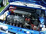
1982 Escort RS1600i with K-Jetronic

1985 Escort XR3i with K-Jetronic
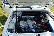
1985 Escort RS Turbo S1 with KE-Jetronic
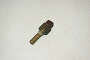
Thermal timer

Components of K-Jetronic


literature
- Gert Hack: This is how it gets faster, VW Tuning Golf-Scirocco-Jetta. 3rd edition, Motorbuchverlag, Stuttgart, 1981, ISBN 3-87943-790-4
- Bosch: Technical briefing K-Jetronic. 2nd edition, Robert Bosch GmbH, Stuttgart, 1978, VDT-U 3/1 De
Individual evidence
- ^ Register information from the German Patent and Trademark Office
- ↑ Bosch product identification list K-Jetronic injection valves ( Memento of the original from June 25, 2016 in the Internet Archive ) Info: The archive link has been inserted automatically and has not yet been checked. Please check the original and archive link according to the instructions and then remove this notice. (PDF)
- ↑ AutoBild classic 12/2013, p. 47
Web links
- Bosch K-Jetronic. (PDF) Robert Bosch GmbH, 1978, accessed on June 25, 2016 (wall chart).