
Phased array antenna

A phased array (from English phased array , phased array ') is a phased array antenna with high directivity , which reaches a concentration of the radiation energy by the arrangement and interconnection of individual radiators. If the individual radiators can be controlled differently, the antenna diagram of the antenna can be pivoted electronically ( electronic beam pivoting ). Phased array technology is often used in radar systems in the military sector.
commitment
In principle, all group antennas and panel antennas are also array antennas, but they have an invariably identical phase position of all radiators to one another. They are used for satellite reception ( weather and communication satellites ), mobile radio stations, radio transmitters ( VHF , VHF , UHF ) and radar systems. 4-square antennas, which are used in amateur radio, work with the transmission and reception direction, which can be selected to a limited extent by switching the phase position.
The greater the transverse extent of the antenna, the stronger the bundling. This is why antennas for mobile communications are stacked vertically, while radar antennas are stacked horizontally. By deliberately deviating the phase position, the directional diagram can be influenced asymmetrically in order to e.g. B. to provide a reconnaissance radar with a directional diagram extended diagonally upwards, but to limit it downwards.
In radars often electronically steerable phased array antennas are used. They allow a moving target to be tracked quickly and accurately. Examples are anti-aircraft missile systems like the American Patriot and the Russian S-300P and 9K330 Tor .
Phased array radars differ in two types. The above-described English Passive Electronically Scanned Array called (PESA), so passive electronic scanning. The second variant of the phased array radar is the Active Electronically Scanned Array (AESA) radar, in which each individual transmitting or receiving element has an HF source. It is mainly used in combat aircraft due to its reduced weight and size.
| advantages | disadvantage |
|---|---|
|
|
history
Yagi antennas arranged in groups and fed phase- synchronously were the first radar antennas, they were used for long-range radio reception and are also widespread among radio amateurs today ( 70 centimeter band ).
Vertical slot antenna arrays consisting of a waveguide were used on Soviet radars (1970s) at frequencies around 1 GHz next to the main antenna to receive the friend-foe identifier , as this could not be received by the strongly bundling, meanwhile further rotated main antenna due to its delay .
The first radar with electronic beam swiveling was the German remote search system FuMG 41/42 Mammut in 1944 .
technology
function
The group antenna uses the phase shift of the transmission elements arranged in a matrix in order to achieve bundling by means of interference . The transmission energy is amplified in the desired direction, while the undesired directions are canceled out by destructive interference. The individual transmission elements do not need any bundling devices.


In order to shift the angle of emission or reception upwards, only the phase angle of the lower elements has to start earlier, the phase angle of the upper elements accordingly later. Due to the difference in transit time, the energy of the lower radiator is no longer in the middle of the antenna, but is in phase with the energy of the upper radiator further up. As a result, the wavefront is angled in relation to the antenna surface and the radiation angle tilts upwards. The phase difference between the radiators (designated as x in the graphic) is constant between the antenna elements and any differences in transit time in the feed line must be taken into account.
If a different phase difference is set by, for example, advancing the phase angle of the outer elements and that of the inner elements, the bundling of the overall antenna is changed, that is, the antenna diagram shape changes. This method is used with a multimode radar to switch from a wider diagram for target search to a very narrow diagram for precise target accompaniment.
For a very narrow antenna diagram, a large number of individual radiators are required, the phase differences between the radiators adding up towards the edge of the antenna group. The phase shifters must therefore achieve a phase shift of almost 360 ° and this phase shift must be implemented extremely quickly. In practice, various detour lines are used, which are switched into the feed line in steps of 22.5 ° when a 4-bit phase shifter is switched with a 16- bit control word. (This control word must also contain information on addressing.)
The air defense radar RRP 117 uses a phased array antenna with 1584 individual radiators, which are combined horizontally in groups, as this radar rotates its antenna and only needs to electronically pan the antenna diagram in elevation.
Theoretically, the beam angle can be almost ± 90 °. In practice, however, only a maximum of ± 60 ° is achieved, since the bundling of the antenna pattern deteriorates rapidly as the radiation angle increases. For a search in a full circle around the antenna, three antenna groups are distributed in practice at an angle of 120 °. Four groups at a distance of 90 ° are more effective, as is used, for example, in the APAR , a marine radar device.

Arrangement options
Frequency-dependent beam swivel
The frequency-dependent beam pivoting is a special case of the phased array antenna, in which the beam pivoting is controlled by the transmission frequency without any phase shifter. The beam swivel is a function of frequency.
A vertical group of antennas is fed in series. At the fundamental frequency, all radiators receive an output of the same phase through structurally identical detour lines, which cause a phase shift of n · 360 ° . All emitters therefore emit the same phase at the same time. The resulting beam is thus perpendicular to the antenna plane.
If the transmission frequency is increased by a few percent, however, the length of the detour lines determined by the design is no longer correct. The detour line is now a little too long. A phase shift occurs from emitter to emitter. The first emitter emits this few percent earlier than the next adjacent emitter and so on. The resulting beam is swiveled upwards by the angle .
Although this type of beam swiveling is very simple, it is limited to a few permanently installed transmission frequencies. In addition to the susceptibility to interference, there are also more restrictions, for example this radar device cannot use pulse compression .
Linear arrays
.png)
Linear phased array antennas consist of rows that are jointly controlled by a phase shifter. A large number of linear arrays arranged vertically one above the other form a plane antenna.
- Advantage: simple arrangement
- Disadvantage: the beam can only be swiveled in one plane
Planar arrays
Planar phased array antennas consist entirely of individual elements with one phase shifter per element. The elements are arranged like in a matrix, the planar arrangement of all elements forms the entire antenna.
- Advantage: the beam can be pivoted in two planes
- Disadvantage: complicated arrangement and much more controlled phase shifters
Feeding the phased array antennas
Phased-array antennas can be line- fed , in which case the energy is conducted in series or in parallel to the antenna elements through coaxial cables or waveguides . Alternatively, the power can also be provided by a central radiator, i.e. with energy that has already been emitted: The antennas are then called "radiation-fed".
Series feed

When the phased array antennas are fed in series, the radiator elements are supplied with the transmission power one after the other. The increasing phase shift due to the longer supply line must be taken into account when setting the phase shifter. A frequency change is not easily possible with a series supply. If a frequency change should nevertheless be made, the computer must also recalculate the phase shift (or mostly in programming practice: use a different phase angle table).
Examples:
Parallel feed

When the phased array antennas are fed in parallel, the transmit power is split in phase at each node. Each radiator element has a lead of the same length and is therefore supplied in phase. This has the advantage that the computer can ignore the length of the supply lines when calculating the phase shift and that the phase shift is not additionally frequency-dependent.
Examples:
Radiation feed
In the case of radiation feed, the transmission energy is distributed to an antenna matrix via a central primary antenna. On the one hand, this can be done from behind and the antenna matrix with the phase shifters conducts the energy through (transmission type). Alternatively, the radiation can also be fed in from the front, then the energy is received by the elements of the antenna matrix, delayed with the phase shifter, reflected at a mismatch and emitted again (reflection type).
Examples:
- MIM-104 Patriot anti-aircraft missile system (transmission type)
- S-300P anti-aircraft missile system (reflection type)
Radars with phased array antennas
Phased array antennas are widely used primarily for military radar devices. This has historically been the case because initially the costs for a phased array antenna were extremely high and only military users could afford these costs. The advantages of an antenna not equipped with mechanical rotating elements played less of a role, because many phased array antennas can still be rotated mechanically. The greatest advantage from a military point of view is the high speed of the possible beam swings, which can favorably influence the time budget of an impulse radar. By using the technologies of digital beam swiveling, it is even possible to focus the antenna in several beam directions at the same time during the reception time. This results in a universally usable multifunctional radar , which replaces several older, highly specialized radar devices for air space reconnaissance , navigation and target accompaniment / target tracking . The disadvantage of a restricted observation sector is effectively compensated for by using several antennas. A so-called 3 antenna, which can simultaneously cover all directions within a hemisphere around the antenna (2 for 360 ° in the lateral angle and another for the 180 ° in the elevation angle), was developed by the Fraunhofer Institute for High Frequency Physics and Radar Technology under the name Crow's Nest - Antenna developed and patented.

Various phased array antennas with different degrees of agility in beam swiveling are now widespread. Electronically rigid antennas ( LVA antennas ) are used in air traffic control to generate a special antenna diagram. A form of frequency-dependent beam swiveling is used with slot antennas and the FMCW radar method in security technology as a barrier radar . Linear arrays that are electronically pivoted only in one direction ( e.g. PAR-80 , RRP 117 ) still use a turntable for the entire antenna. Planar arrays, which in some cases completely dispense with mechanical movement, are used, for example, in the APAR , AN / MPQ-53 and the Cobra Dane . It is particularly advantageous that planar arrays can electronically compensate for possible pitching , yawing and rolling of an airborne or maritime antenna carrier. The distribution of the individual radiator elements of a phased array antenna does not always have to take place in a flat surface. Antennas are already being built which, in terms of their geometrical shape, adapt precisely to the aerodynamic cross-section of the leading edge of an aircraft wing, for example .
Picture gallery
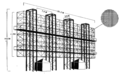
Drawing of the German remote search system FuMG 41/42 Mammut

Reconnaissance and surveillance radar of the Russian anti-aircraft missile complex S-300P

Installation of a phased array radar
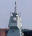
The APAR on the frigate "Sachsen"


Web links
literature
- Heinz Lueg : Experimental and theoretical investigations on laboratory models of phased array antennas . Documentation Center of the Bundeswehr , Bonn 1975.
Individual evidence
- ↑ Franz Kramer: 4-square antennas in theory and practice. In: RRDXA.org. Rhein Ruhr DX Association, June 2014, accessed on November 8, 2019 .
- ↑ http://www.100-jahre-radar.de/index.html?/gdr_5_deutschefunkmesstechnikim2wk.html
- ↑ see digital beamforming, described in the radar tutorial ( online )
- ↑ see crow's nest antenna, described in the radar tutorial ( online )