
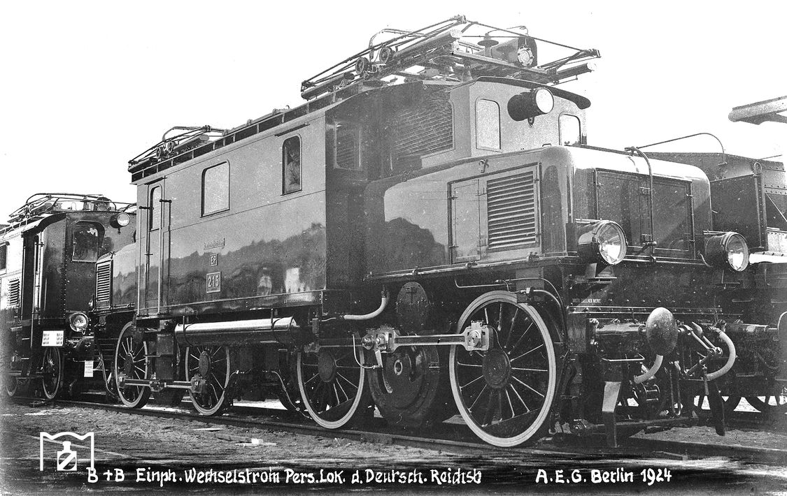
Prussian EP 213 to EP 219
| Prussian EP 213 to EP 214 DR series E 42 1 Prussian EP 215 to EP 219 DR series E 42 2 |
|
|---|---|
 EP 214
|
|
| Numbering: | pr. EP 213 - EP 214 E 42 13 - E 42 14 (DR) pr. EP 215 - EP 219 E 42 15 - E 42 19 |
| Number: | EP 213 - EP 214: 2 EP 215 - EP 219: 5 |
| Manufacturer: | EP 213 - EP 214: BMAG / MSW EP 215 - EP 219: AEG |
| Year of construction (s): | 1924 |
| Retirement: | 1960 |
| Axis formula : | B'B 'w2k |
| Gauge : | 1435 mm ( standard gauge ) |
| Length over buffers: | EP 213 - EP 214: 12,900 mm EP 215 - EP 219: 13,380 mm |
| Total wheelbase: | EP 213-214: 9,100 mm EP 215-219: 9,380 mm |
| Service mass: | EP 213 - EP 214: 76.0 t EP 215 - EP 219: 77.2 t |
| Top speed: | 70 km / h |
| Hourly output : | EP 213 - EP 214: 840 kW (at 45 km / h) EP 215 - EP 219: 780 kW (at 54 km / h) |
| Continuous output : | EP 213 - EP 214: 740 kW (at 65 km / h) EP 215 - EP 219: 595 kW (at 65 km / h) |
| Starting tractive effort: | 135 kN |
| Driving wheel diameter: | 1,500 mm |
| Power system : | 15 kV 16 2 / 3 Hz single-phase |
| Power transmission: | Overhead line |
| Number of traction motors: | 2 |
| Drive: | Connecting rods |
| Type of speed switch: | 15 steps |
The twin-engine electric locomotives with the initial designation EP 213 to EP 214 and the slightly different EP 215 to EP 219 of the Prussian State Railroad were from the Deutsche Reichsbahn from 1926 as the E 42 1 series with the numbers E 42 13 - E 42 14 or as a series E 42 2 classified with E 42 15 - E 42 19. Structurally, they were designed for passenger train service.
history

For the electrification of the Berlin light rail with 15,000 volts alternating current, the Prussian state parliament approved, in addition to other vehicle purchases, the procurement of four two-axle drive frames with electric motors that could be tensioned in front of a train. The power supply from the overhead line should come from a pantograph on the roof of the first train car. These were commissioned by the Central Railway Office in Berlin from Berliner Maschinenbau AG (BMAG; mechanical part) and Maffei-Schwartzkopff-Werken (MSW; electrical part). After 1914 on the Dessau-Bitterfeld test line it was already possible to determine whether they were successful, during the First World War all three motor bogies were also tested on the lines of the KED Breslau . In 1920, the State Railroad placed an order with BMAG (mechanical part) and Maffei-Schwartzkopff Werke in Berlin for the production of four and with AEG for the production of 11 further motorized frames at a speed of 70 km / h.
A little later, however, the newly founded Deutsche Reichsbahn decided to electrify the Berlin Stadtbahn for operation with 750 volts direct current over power rails . For the motor bogies commissioned, this was changed in 1922 so that the two locomotives EP 213 and EP 214 based on the design model of EG 511 ff. And from ten motor bogies from AEG the locomotives EP 215 were made from the four motor bogies that BMAG has now completed until EP 219 were produced. There is contradicting information about the existing motor bogies; on the one hand, two motor bogies are said to have been used for the construction of the EG 528 . The EB 3 is said to have gone back to the AEG company as a spare parts donor. This theory is supported by the fact that the EB 1-3 and the EG 528 have the same speed, namely 65 km / h. This theory has not yet been fully proven, only for EP 213 to EP 219 the existing motor bogies were not used, as can be read again and again in some sources.
The “improvisations” of 1924 proved to be very useful and robust and were also in service with light freight trains in passenger train service on the Silesian Mountain Railway and on lowland routes. Equipped with two electric motors, they were also superior to the E 30 in terms of performance , so that this series could be completely dispensed with. This also included the fact that all locomotives had the option of electric train heating from the start. In the strenuous mountain service, the engines of the locomotives were often loaded to the limit temperature, but this did not harm them due to their robust design. During the test service, passenger trains with a load of 401 t were transported at a 5 ‰ gradient at a speed of 63 km / h and at 10 ‰ at 58 km / h. With a gradient of 20 ‰, 273 t could be transported at a speed of 50 km / h. From 1927 the locomotives were designated as E 42.13 - E.42.19 . The E 42 13 retired due to an accident in 1941; furthermore the E 42.16 and 19 were lost due to war events . the remaining E 42 14, 15, 17 and 18 were brought to the USSR as reparations at the end of the war ; after their return, all four locomotives were in the Deutsche Reichsbahn's damaged park from 1953 until they were scrapped in 1960 .
Constructive features

Like their freight locomotive counterpart EG 511 ff. , Which appeared ten years earlier, the locomotives were a simple and robust construction, although technically out of date when they were built. Both motor bogies used for them were movably connected to one another by means of a coupling and carried a common bridge frame. The structure on top consisted of the engine room with the main transformer and the driver's cabs at the ends. The swiveling engine frames each carried a permanently mounted hood, which in the overall appearance formed a “front structure” in front of each machine room face. The respective traction motor and a compressor were located under this engine frame cover. Above this was another, recessed cover with ventilation grilles for the motor fan unit up to roof height. Two pantographs with bar separators and an exhaust air attachment were arranged on the roof, which was drawn over both ends of the engine room box.
The essential parts of the electrical equipment were an externally ventilated oil transformer , two externally ventilated 20-pole AC series motors with reversing poles, which essentially corresponded to those of EG 511 ff. , As well as a manually operated travel switch (series E 42 1 ) or an electromagnetic contactor control for each driver's cab (Series E 42 2 ) with 15 continuous speed levels each. The direction of travel was changed on the locomotives by four electromagnetic contactors. The transformer was cooled in a closed circuit using transformer oil .
The power transmission from the traction motors to the axles was carried out for each drive frame via spring-loaded helical-toothed motor pinions on both sides, a jackshaft and the rod drive with coupling rods analogous to the E 71.1 . The bogie frames were a complete cast part. The connection between the front end and the middle part of the locomotive was made by bellows. There was also a door in the driver's cab so that checks could be carried out in the front building after the machine system.
literature
- Dieter Bäzold, Günther Fiebig: Railway Vehicle Archive 4, Electric Locomotives, Transpress-Verlag Berlin, 1970.
- Glanert / Scherrans / Borbe / Lüderitz AC train operation in Germany, Volume 2, Electric in the Silesian Mountains , Oldenburg Industrieverlag Munich, 2011, ISBN 978-3-8356-3218-9 .
Web links
- Association of Silesian Mountain Railways, passenger train electric locomotive EP 213-214, with pictures
- Association of Silesian Mountain Railways, passenger train electric locomotive EP 215-219, with pictures
- EP 216 or E 42 15 as a model
- Photo of the E 42.15 1924 on the Joachim Schmidt Railway Foundation
Individual evidence
- ↑ a b Association of Silesian Mountain Railways, passenger train electric locomotive EP 213-214
- ↑ a b Association of Silesian Mountain Railways, passenger train electric locomotive EP 215-219
- ↑ Glanert / Scherrans / Borbe / Lüderitz AC train operation in Germany, Volume 2, Electric in the Silesian Mountains , Oldenburg Industrieverlag Munich, 2011, ISBN 978-3-8356-3218-9 , p. 110.
- ↑ Glanert / Scherrans / Borbe / Lüderitz AC train operation in Germany, Volume 2, Electric in the Silesian Mountains , Oldenburg Industrieverlag Munich, 2011, ISBN 978-3-8356-3218-9 , p. 120.
- ↑ a b Glanert / Scherrans / Borbe / Lüderitz alternating current train operation in Germany, Volume 2, Electric in the Silesian Mountains , Oldenburg Industrieverlag Munich, 2011, ISBN 978-3-8356-3218-9 , p. 141.
- ↑ a b c d Dieter Bäzold, Günther Fiebig: Railway Vehicle Archive 4, Electric Locomotives, Transpress-Verlag Berlin, 1970, p. 113.
- ↑ Dieter Bäzold et al. EP 213 and 214 Breslau , in: Preußen-Report Volume 10, page 66, Hermann Merker Verlag, Fürstenfeldbruck, 1997, ISBN 3-89610-005-X .
- ↑ Dieter Bäzold, Günther Fiebig: Railway Vehicle Archive 4, Electric Locomotives, Transpress-Verlag Berlin, 1970, p. 114.