
Prussian EP 202 to EP 208
| Prussian EP 202 to EP 208 DR series E 30 |
|
|---|---|
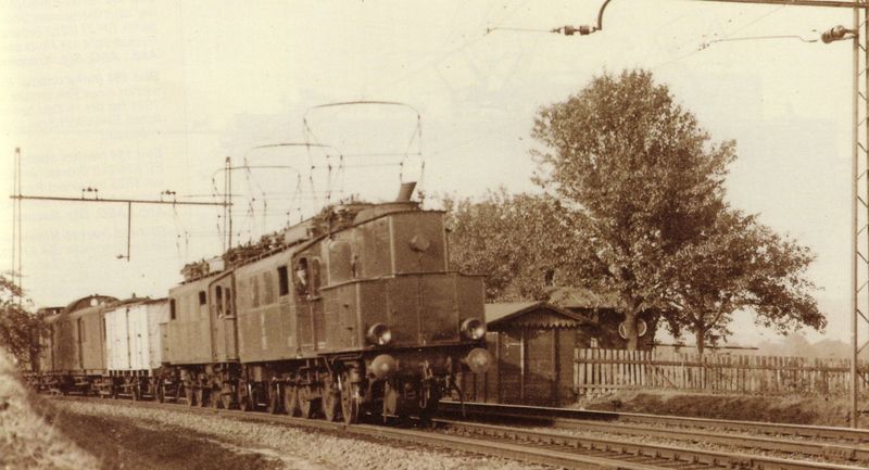
 Production photo of EP 202
|
|
| Numbering: | EP 202-208 DR: E 30 02-08 |
| Number: | 7th |
| Manufacturer: |
BMAG mech. Part Maffei - Schwartzkopff -Werke (MSW) electr. part |
| Year of construction (s): | 1914, 1920 (2 locomotives) |
| Axis formula : | 1'C1 ' |
| Gauge : | 1435 mm ( standard gauge ) |
| Length over buffers: | 12,950 mm |
| Total wheelbase: | 8,000 mm |
| Service mass: | 82.5 t |
| Friction mass: | 51.5 t |
| Wheel set mass : | 17.5 t |
| Top speed: | 90 km / h |
| Hourly output : | 598 kW |
| Continuous output : | 538 kW |
| Starting tractive effort: | 107.9 kN |
| Performance indicator: | 7.25 kW / t |
| Driving wheel diameter: | 1250 mm |
| Impeller diameter: | 1,000 mm |
| Power system : | 15 kV 16 2/3 Hz |
| Power transmission: | Overhead line |
| Number of traction motors: | 1 |
| Drive: | Connecting rods |
| Type of speed switch: | 16 continuous speed levels |
| Train brake: | Compressed air brake type Knorr |
| Control: | Load switch / cam switch control with additional transformer |
The EP 202 to EP 208 were electric locomotives of the Prussian State Railways for passenger train service in the Silesian network . At the Deutsche Reichsbahn they were classified in the class E 30 in 1925 .
history
The locomotives were built because not only electric multiple units were to be used on the Silesian branch lines to Liebau and Halbstadt . The Prussian State Railroad therefore ordered seven 1'C locomotives in 1913. However, these were carried out with a 1'C1 ' wheel arrangement so that the boiler for the steam-heated car sets could be added.
The first locomotive with the number EP 202 was put into operation in 1915. However, due to the First World War, the construction of the next copies could not progress quickly and so they only followed in 1917 (EP 203, EP 204), 1918 (EP 205), 1919 (EP 206), 1920 (EP 207) and 1921 (EP 208). At the beginning they ran on the Nieder Salzbrunn – Halbstadt line , but there they were replaced by the ET 507, later ET 88 , railcars from 1920 .
Then the locomotives carried the passenger trains on the Silesian Mountain Railway between Hirschberg and Königszelt , as the Prussian EP 236 to 246 intended for this purpose had not yet been delivered. However, the locomotives were not suitable for the heavy loads, which led to great wear and tear and many breakdowns.
After the delivery of EP 236 to 246 and EP 213 ff. (Later series E 42 1 + 2 ), EP 202-208 were handed over to the central German network in 1924, where they were located in the Bitterfeld and Rothensee depots. On the flat land routes there, they initially performed well until increasing train loads caused damage again through overuse. The installation of used parts from the decommissioned express train locomotives ES 9 to ES 19 (which had identical traction motors) now enabled inexpensive maintenance. To protect the locomotives, heavy trains were also driven with a leader locomotive.
In the years 1927 to 1930, the Deutsche Reichsbahn decommissioned the locomotives. None of them remained in the museum.
Constructive features

The frame of the locomotive was divided into three parts. It consisted of the middle engine support frame, which in addition to the engine accommodated the first and second drive axles and the jackshaft. A frame piece to support the front barrel axle and a frame piece to accommodate the rear drive axle and barrel axle were riveted to the rear. The frame was stiffened by the engine cross member, the buffer beam and other cross stiffeners. The axles were guided in it, of which the front barrel axle was a Bissel axle and the rear an Adam axle . The middle drive axle was laterally displaceable, the others were fixed in the frame. The locomotive body, riveted to the frame, was made from a sheet-metal-clad profile steel frame. The front driver's cab was designed as a final driver's cab, the rear one as a set back. The boiler was placed in the anteroom in front of him. The driver's cabs were lined with wood on the inside, the roof hoods were removable. The front of the boiler gave the locomotive its characteristic asymmetrical appearance.
The drive of the locomotive was designed with an inclined drive rod and a jackshaft , the structure was basically the same as that of the E 01 . The brake was designed as a block brake , with it each coupling axle could be braked on both sides. The locomotive also had a throw lever brake as a handbrake. The first two wheels in the direction of travel could be sanded.
The main transformer of the locomotive was designed as an oil-cooled one. It was manufactured in a core construction with separate windings. The electrical equipment also included the two pantographs , the roof cables mounted on insulators and the main switch stationed under the roof skin . The traction motor was designed as a single-phase series motor with reversible pole winding, it had an armature diameter of 2.4 meters, which is to be noted, two armature windings that are constantly connected in series, and subdivided commutators . The motor was controlled by a hand-operated cam switch mechanism , just as it was designed for the E 01 . It had a shift drum with 16 continuous speed levels. The direction of travel was reversed with an additional switch drum, with which the exciter winding of the drive motor was switched.
The auxiliaries were designed in the same way as for the E 01 , they consisted of the auxiliary transformer electrically and the boiler mechanically. The auxiliary transformer was responsible for various auxiliary elements and was fed from the main transformer during operation and from a control line when it was switched off. The boiler was a coke-fired steam boiler for heating the car. A passenger train could be heated for three hours at a pressure of 10 bar.
literature
- Andreas Wagner, Dieter Bäzold, Rainer Zschech, Ralph Lüderitz: Lokomotivarchiv Preußen, Vol. 4: Cogwheel and narrow-gauge steam locomotives, electric locomotives and railcars . transpress Verlagsgesellschaft, Berlin 1991, pp. 51-53, ISBN 3-344-70705-1 .
- Dieter Bäzold, Günther Fiebig: Railway Vehicle Archive 4, Electric Locomotives, Transpress-Verlag Berlin, 1970
Web links
- Data and photos - Silesian Mountain Railways Association
- Data sheet on lokodex.de
- Data sheet on lokomotive-online.com
- Website of the EP 202 as a model at BRAWA
Individual evidence
- ↑ Photo of the locomotive with the boiler in front.
- ↑ Dieter Bäzold, Günther Fiebig: Railway Vehicle Archive 4, Electric Locomotives, Transpress-Verlag Berlin, 1970, page 100