Hall sensor
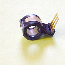
A Hall sensor [ 'hɔːl -] (also Hall probe or Hall sensor , according to Edwin Hall ) uses the Hall effect to measure magnetic fields .
Structure and functionality

Hall sensors consist of the thinnest possible crystalline doped semiconductor layers that usually have four electrodes on the sides. A current is fed in through the two opposing electrodes , the two orthogonal electrodes serve to decrease the Hall voltage. If such a Hall sensor is traversed by a magnetic field running perpendicular to the layer, it supplies an output voltage that is proportional to the (signed) amount of the vector product of magnetic flux density and current. The cause is the Lorentz force on the moving majority charge carriers in the layer. It is proportional to the current, to the charge carrier mobility and inversely proportional to the layer thickness (the thinner the layer, the greater the charge carrier speed and the greater the Lorentz force). The electric field established between the measuring electrodes is in equilibrium with the Hall voltage and prevents further charge carrier separation.
The Hall voltage is also temperature-dependent and can have an offset . Due to the proportionality of the Hall voltage to the charge carrier mobility and the concentration of the majority charge carriers, the Hall effect is an established method of determining these parameters in semiconductor technology.
A Hall sensor also delivers a signal when the magnetic field in which it is located is constant. This is the advantage compared to a simple coil as a magnetic field sensor (e.g. induction loop, Rogowski coil), which can only determine the derivative of the magnetic field over time. Another important advantage of Hall sensors is that no ferromagnetic or ferrimagnetic materials (such as nickel or iron) are required for their implementation. This means that the magnetic field to be measured is not changed just by bringing the sensor into it. Magnetoresistive sensors or fluxgate magnetometers do not have this property.
Designs and types
Analog or ratiometric Hall sensors deliver a signal proportional to the magnetic field or a digitized value.
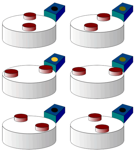
In Hall sensors as proximity switches , the signal from an analog Hall sensor is converted into a yes / no signal via a comparator .
Discrete Hall sensors
Uniaxial Hall sensors are made from thin semiconductor layers. In silicon (Si), with a charge carrier mobility of approx. 1500 cm / Vs, sensitivities of 0.2–0.25 V / T are achieved, with III-V semiconductors such as e.g. B. indium antimonide (InSb) with a charge carrier mobility of 80,000 cm / Vs even sensitivities of up to 16 V / T are achieved. Typical designs are:
- Rectangular shape
- Butterfly shape
- Cross shape
To compensate for the current dependence of the signal, the sensors are operated with constant current. An instrument amplifier (differential amplifier) is used to decrease the Hall voltage, so that the differential voltage can be measured with a high input resistance, which does not occur potential-free at the sensor at the level of half the operating voltage. It is related to ground by means of the differential amplifier for better further processing.
Integrated hall sensors
Hall elements are usually integrated in circuits in which signal amplification , analog-digital conversion , digital signal processing , offset and temperature compensation and sensitivity correction take place.
The disadvantage of the lower sensitivity of CMOS- integrated Hall sensors is more than compensated for by the integrated signal processing and sensor ICs are available in which the complete signal processing takes place automatically. The offset of the Hall sensors is reduced by a special operating mode of the sensor element, the so-called spinning current mode . Non-linearities are compensated by correction functions that are stored in the IC in the form of tables of values. The sensor only needs to be connected and provides a digital or analog output signal.
With integrated Hall sensors, between
- lateral Hall sensors (measurement of the magnetic flux density perpendicular to the chip surface) and
- vertical Hall sensors (measurement of the magnetic flux density parallel to the chip surface).
Lateral Hall sensors
The typical designs of the lateral Hall sensors correspond to those of the discrete Hall sensors.
Vertical hall sensors
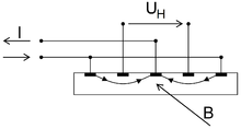
As the Hall elements can only be contacted on the surface in CMOS processes, vertical Hall sensors differ significantly from lateral Hall sensors. The typical design is a so-called 5-pin, which has 5 contacts in a row.
Vertical Hall elements have been around for over 30 years, but their poorer properties have made them rarely used in industrial applications. Only in the last few years has a wide variety of measures such as B. the forced symmetrization succeeded in improving their properties so much that they can now be found in the first series products.
3D Hall sensors
If lateral and vertical Hall elements are placed together on a chip, the three-dimensional vector of the magnetic flux density (Bx, By, Bz) can be measured. For this purpose, several Hall elements (usually 4) are used per direction and arranged point-symmetrically around a center point. The 3D Hall sensor can measure point-like, so to speak. Another principle uses several uniaxial Hall sensors to measure all three components of the magnetic field with the help of a small (with integrated) flux concentrator.
Gradient Hall sensors
If two Hall elements are placed next to one another at a certain distance, the Hall sensor can be made robust against homogeneous interference fields by differential evaluation of the Hall sensor signals. The difference quotient is understood as the gradient of the magnetic field. These gradient Hall sensors are particularly suitable for measuring systems that can work on a gradient, such as E.g .: position measuring systems and current sensors. A Hall sensor IC with nine 3D Hall sensors can measure not only the three-dimensional vector of the magnetic flux density but also the first and second derivative of the magnetic field at one point.
Applications

- Magnetic field measurement ( magnetic flux density )
- Potential-free current measurement (current sensor): If the magnetic field is generated by a current-carrying conductor or a coil, the current in this conductor or coil can be measured potential-free . B. with current clamps.
- non-contact and contactless signaling devices
- Layer thickness gauges
- Commutation of electronically commutated motors
- Position detection of moving permanent magnets.
- Magnetic field cameras
Hall sensors are used in a variety of ways in the automotive industry , e.g. B. in the seat belt buckle , as wheel speed sensors, in the door locking system, in the pedal status detection, in the gear shift or to detect the ignition point. The main advantage is the insensitivity to (non-magnetic) dirt and water. In power plant technology, Hall sensors are used, for example, to record the turbine speed.
They are also found in brushless motors such. B. with PC fans and floppy disk drives.
There are also computer keyboards with Hall sensors under each key.
Hall sensors with analog signal outputs are used to measure very weak magnetic fields (geomagnetic field), e.g. B. used as a compass in navigation systems.
As current sensors , they are used in the gap in the iron core of a coil or conductor through which the measuring current flows. Such current sensors are offered as a complete component, are very fast, can, in contrast to current transformers, also be used to measure direct currents and offer potential separation between the power circuits, which are usually connected to the power supply, and the control electronics.
As position detection sensors or contactless buttons, they work in conjunction with permanent magnets and have an integrated threshold switch.
Hall sensors can also be used in conjunction with an excitation coil instead of a receiver coil in metal detectors .
Spinning current operation with Hall sensors
In order to suppress the offset voltage caused by geometrical errors , piezoresistive effects , inhomogeneous temperatures, etc., Hall sensors with several connections (usually 4) are designed to be rotationally symmetrical. Hall contacts are thus implemented identically in terms of their shape as current contacts. Two of these connections serve as power supply, two as Hall voltage pickups. The functions of the connections are swapped in turn. The offset voltage is significantly reduced by evaluating the measurement results accordingly. It is possible to realize this spinning current operation both spatially and temporally. Spatial means that several Hall sensors are implemented in close spatial proximity and operated simultaneously with different current directions. Temporal means that a Hall sensor is operated one after the other with different current directions. The final measured value is the mean value from the individual measured values of the different operating current directions. In particularly high-quality Hall sensors, both approaches are even used in combination. These methods are mainly used with integrated sensors and use the periodicity of the piezoresistive constants in the chip level in order to reduce the otherwise very large offset of the sensors extremely strongly (approx. Factor 1000 to 10000).
Characteristic values
The sensitivity of ratiometric Hall sensors is given in volts per Tesla (V / T) or in millivolts per Gauss (mV / G).
In addition, mV / VT, mV / AT, mV / mA-mT etc. are also used. The supply / test voltage or current is included in the specification for the sensitivity.
See also
literature
- Josef Janisch: Small effect - big effect . In: electronics industry . No. 7 , 2006, ISSN 0374-3144 ( all-electronics.de [PDF; accessed on March 2, 2015]).
Individual evidence
- ↑ https://aip.scitation.org/doi/full/10.1063/1.4990470 Florian Werner: Hall measurements on low-mobility thin films , in Journal of Applied Physics Vol. 122 Issue 13 (October 2017), accessed on Feb. 18 . 2019
- ^ RS Popovic: The Vertical Hall Effect Device. In: IEEE Electron Device Letters. Volume 5, 1984, pp. 357–358.
- ↑ Patent: Vertical Hall sensor
- ↑ M. Hackner, H.-P. Hohe, M. Stahl-Offergeld: An Integrated Nine-Dimension Hall-Gradient-Sensor In: Sensor + Test Conference 2009, Proceedings, Sensor 2009, Volume II, ISBN 978-3-9810993-5-5 , pp. 23-28
- ↑ freepatentsonline.com


