Delay line
Delay lines ( English line delay , correct: delay line ) are used for time shift or temporary storage (run-time memory) of a serial signal (analog or digital) by means of the signal propagation time in an electric line of a certain length or in an acoustic transmission path.
The delay time results from the quotient of length and wave speed.
Working principle
Electromagnetic delay line
The delay occurs without signal conversion through an electrical line or an equivalent arrangement of a certain length. A wire-bound electromagnetic wave propagates on the line / structure. The geometric length can be significantly less than the electrically effective length for signal delay, z. B .:
- A dielectric with a relative permittivity ( ε ) greater than 1 causes a so-called shortening factor .
- A ferromagnetic material with permeability ( μ )> 1 also causes a shortening.
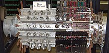
- Inductance coupled over the length causes a geometric shortening (wire helix, see picture, but also in traveling wave tubes ).
- With concessions to the signal bandwidth, the “line” can also be built up from discrete inductances and capacitances in order to achieve a long runtime.
- The line can consist of resonators ( cavity resonators , comb-like structures); it is then only effective in a narrow frequency band and is usually used to adjust the speed (delay) of the wave to a stream of electrons (examples: undulators in free-electron lasers , slot anodes of magnetrons )
A combination of the above measures is also possible.
Electronic delay line
An electronic form of a delay line is the so-called bucket chain store , in which the charges of a large number of capacitors are passed on to the next in response to a clock signal. The principle is known in the form of integrated circuits as a bucket chain store (English charge-coupled device , CCD). Since this principle works time-discrete, the bandwidth is limited to half the clock frequency. The digital form are FIFO memories, this is also implemented with DRAMs .
Acoustic delay line
In acoustic delay lines, the electrical signal is converted into ultrasound using piezoelectric transducers , passed through a medium with a defined speed of sound , and then converted back into an electrical signal.
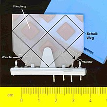
The picture on the right shows a PAL ultrasonic delay line: the two piezoelectric transducers are glued to the front of a glass plate in the form of narrow strips; only the aluminum connecting wires can be seen. In order to limit the size of the glass plate, reflections on the edges of the glass medium are used. In order to limit the wave propagation and the signal path in a defined manner, square damping pads are applied to the glass plate. Potassium lead glass is used , which compared to lighter glass has a lower speed of sound (about 2500 to 2540 m / s) and also has a low temperature coefficient of the propagation speed.
In the past, mercury was also used as a sound propagation medium; another principle uses magnetostrictively excited wires. See also the history section .
Mechanical delay line
Mechanical reverberation devices ( spring reverbs ) are in principle also delay lines.
application
Television reception technology

Ultrasonic delay lines were used in color television sets according to the television standards PAL and SECAM until around 1995 in order to delay the color carrier signal by the transit time of around one picture line. As a result, with PAL, phase errors, which are expressed in color tone errors, can be efficiently suppressed by averaging the color signals of two consecutive image lines (the phase errors cancel each other out) by means of the phase-alternating color carrier signal; With SECAM, which transmits only one of the two color difference signals per image line, the circuit can only access the other color difference signal (from the previous line) by using a delay line. The use of a delay line is therefore only desirable for PAL in order to increase the picture quality, whereas it is absolutely necessary for SECAM. In the US NTSC color television process developed in the early 1950s , the chrominance (color) signal in each line is independent of the neighboring lines; Receivers for the NTSC standard therefore do not have a delay line. After the two chrominance signals YR (red difference) and YB (blue difference) have been demodulated from the color carrier signal , in all three systems, together with the luminance signal Y , the three RGB components (red, green, blue) for controlling the three electron guns of the color picture tube are generated won.
In the case of ultrasonic delay lines, the signal delay of the quadrature amplitude modulated PAL color carrier signal with a carrier frequency of 4.43361875 MHz is carried out in the bandpass position. The subtraction of the modulated color components is achieved by delaying a half-integer number of oscillations of the color subcarrier frequency and amounts to 283.5 periods. This results in a delay of:
In later PAL color television receivers the delay of the two already demodulated color carrier signals YR and YB in the baseband position was carried out with a delay of exactly one image line of 64 µs by means of two synchronized SC filters . In contrast to the ultrasonic delay lines, delay chains in the form of SC filter chains can be manufactured as an integrated circuit , are smaller and mechanically more robust.
Since 2000, conventional digital television sets have been using multi- standard decoders with integrated delay chains to receive analog television signals .
Audio technology
Electronic signal delays after the bucket brigade principle , known as BBD (Engl. Bucket brigade memory (BBM) or Bucket Brigade Device (BBD)) are used to noise affecting recognize in good time and to be able to hide or to the spatial hearing impression, by adding the delayed signal components .
In principle, echo and reverberation devices are also coupled delay lines. In the past, mechanical processes with an acoustically excited coil spring were also used for this ( spring reverb ).
Scientific equipment and radio frequency
In research, it is often necessary to delay signals or impulses in order to compensate for time shifts, to enable acquisition or to synchronize trigger times.
Delay times in the nanosecond and sub-nanosecond range are often guaranteed by defined cable lengths. These can be permanently installed cables or coaxial laboratory cables.
In high-frequency technology and in antenna construction , it is often necessary to distribute or merge signals with the correct phase. The delay lines used for this are also called detour lines .
history

In early computers like ACE , UNIVAC I or EDSAC , delay lines were used as dynamic main memory. In contrast to a random access memory ( RAM ), it was not possible to access every data element randomly, but had to wait until it reappeared at the end of the runtime memory. In ICL terminals , this technique was still used as screen memory in the 1970s. In the computers 5005/5006 and 5610 from Singer Business Machines, delay lines were used as the main memory.
Mercury runtime storage systems consisted of a tube filled with mercury, with an oscillating crystal attached to both ends . An electrical signal stimulated one of the two quartz oscillators to vibrate mechanically and led to ultrasonic waves in the mercury, which continued at a speed of 1.4 km / s and, after a corresponding delay, caused the other quartz oscillator to generate another electrical signal. Synchronous to the clock of the arithmetic unit, the corresponding bit signals were either sent back to the runtime memory or replaced by other bits. So you could run a serial bit pattern of a certain length and thus save it. In this way, the storage takes place in the mercury alone through the signal transit time of the acoustic wave , in the ACE with a clock rate of 1 MHz and a transit time of 1.024 ms this was 1024 bits.
Mercury delay lines were previously used in RADAR technology for analog signals during World War II.
Another variant of the delay line for transit time memories used nickel wire - this used the magnetostriction effect in nickel for writing / reading and a long rolled up nickel wire for storage. Such delay lines were used in particular in desktop computers, in which core memory was too expensive and the lower computing speed was unproblematic.
A third variant uses glass as the medium for the acoustic wave. It was used in color television sets for the (analog) storage of the signal of a line using the SECAM and PAL methods to correct color errors. By using multiple reflections in the glass body, the originally 15 cm long unit could be reduced significantly.
See also
Web links
- Magnetostrictive runtime memory in the lexicon of a development association for the history of technology
- Runtime memory , still in use in a museum
Individual evidence
- ^ Otto Limann: Television technology without ballast. Introduction to the circuit technology of black and white and color television receivers with tubes, transistors and integrated circuits. 10th, completely revised and expanded edition. Franzis-Verlag, Munich 1973, ISBN 3-7723-5270-7 , p. 179: transit time cable .
- ↑ E.g. Hackethal, cable type HH1000 with 0.13 μS / m inner conductor only coiled, cable type HH2500 with 1.9 μS / m inner conductor coiled and high-frequency iron in the core insulator. Source Brochure Hackethal 1955
- ↑ Article about an f / U converter using an acoustic delay line ( Memento from September 10, 2012 in the web archive archive.today )
- ↑ Data sheet of the PAL ultrasonic delay line DL700 , manufacturer Philips, manufacturer number: 84701
- ↑ Wolfgang Scheida: 40 years of PAL color television 1967–2007 . In: Funkgeschichte. No. 174, August / September 2007, ISSN 0178-7349 , pp. 5–7, (PDF; 885 kB).
- ↑ Data sheet (PDF; 64 kB) TDA4661 - Baseband Delay Line
- ↑ ADV7181 data sheet NTSC / PAL / SECAM video decoder


