Stripline

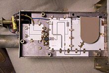
As a strip line ( English microstrip ), a certain class of electrical waveguides , respectively. What all striplines have in common is that they consist of one or more thin, conductive strips that are applied to a dielectric. Stripline structures can, for. B. consist of line strips arranged in one plane. They are often isolated in or above a metallic surface.
The field of application is high-frequency technology and there, above all, the area of microwaves - striplines can be used to create cost-effective and reproducible defined impedances in circuits for the transmission, coupling and filtering of high signal frequencies.
The feed and the radiator elements of antennas can also be designed as strip conductors.
Synonyms and differentiation from other terms
- The English word microstrip describes the arrangement on the surface of an insulating plate (circuit board or ceramic).
- The English stripline is used for the symmetrical stripline . An offset stripline is such a stripline with different distances to the ground planes .
- According to this terminology, the coplanar line ( coplanar waveguide ) is a microstrip , “framed” in a groundplane , ie a ground plane in the same plane.
The term microstrip line is by far the most common and often used for all types of construction. It is therefore advisable to separate the terms based on English usage.
The description of the designs suggests that printed circuits (circuit boards) are generally strip lines. The structure of the strip conductors is basically the same, but they are not necessarily dimensioned and operated as waveguides. Parameters that are decisive for striplines (impedance, loss factor, wave propagation speed, dispersion, radiation) must be taken into account for circuit paths with fast switching processes <1 ns. The frequency only plays a subordinate role here.
Properties as a waveguide
Striplines are dimensioned in such a way that, as a rule, only quasi-TEM waves can propagate. With a few simplifications, these can be viewed almost like TEM waves : both the electrical and the magnetic fields run almost exclusively perpendicular to the direction of propagation, as is also the case in coaxial lines or two-wire lines . A condition for this is that the transverse dimensions of the lines are small compared to the wavelength. Striplines are only used for short distances within assemblies.
The advantage of striplines is that they can be manufactured inexpensively, reproducibly and economically. This is particularly important for complex circuits in which there are also other components made up of striplines.
Another advantage is the low field propagation outside the planar structure, which is why there is only a small amount of waves emitted into space. Therefore, high-frequency circuits manufactured using stripline technology can often be operated without a housing that is closed on all sides or without individual, separate chambers.

The wave impedance of a stripline is determined by its width and by the thickness and dielectric constant of the insulator substrate. Since the last two quantities are usually constant, the calculation and simulation of stripline circuits is made easier. A calculation tool can be found in.
In addition to processing high-frequency signals, stripline structures are also used in or as antennas . They often form both the feeding and adapting components and the radiating elements themselves on a common substrate. Examples are the patch antenna , the spiral antenna , the panel antenna and also dipole antennas . All of these antennas can be manufactured entirely from planar stripline structures. Also helical antennas are often made of strip conductors, here they are, however, wrapped around a cylinder or cone. In all of these cases, the phase positions and impedances of the line-bound waves are caused by varying the length and width of the striplines so that their fields are superimposed in such a way that (often directed) radiation takes place as radio waves .
Designs
There is a large number of designs which, under certain circumstances, can also be used in combination. This includes:
- Microstrip line
- Symmetrical stripline
- Coplanar line, symmetrical or asymmetrical
- Double ribbon cable
- Unshielded slot lines (component e.g. of the Vivaldi antenna )
- Shielded, d. H. Slot lines built into a waveguide (also called fin lines):
- unilateral final management
- bilateral final management
- antipodal fin leadership
Microstrip line
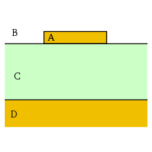
As microstrip lines , strip lines referred to, which consist of a conductive strip, which are separated by a dielectric substrate by a conductive surface. They are mostly used for the transport and processing of electromagnetic waves in the range between a few hundred megahertz and around 20 gigahertz.
A microstrip line consists of a non-conductive substrate ( printed circuit board ), which is completely metallized on the underside ( ground plane ). A conductor in the form of a strip (conductor track), i.e. with a defined cross-sectional area, is arranged on the top. This strip is usually made by machining the top metallization by etching or milling.
Various dielectrics are used as the substrate. Glass fiber reinforced PTFE ( RT / Duroid ) is used very frequently . For higher demands, aluminum oxide is used alongside other ceramic materials. The FR4 (glass fiber reinforced epoxy resin ), which is common in normal circuit board production, is generally unsuitable for frequencies above a few GHz because its loss angle is too large.
On the one hand, the signal spreads in the space between the strip conductor and the ground plane. On the other hand, the field lines also enter the free space above the stripline, which is usually filled with air. One must therefore speak of an inhomogeneous dielectric.
If the stripline is interrupted, the signal can jump over the gap under certain conditions and then continue to spread.
Line impedance

For microstrip lines on printed circuit boards, an exact solution for the line impedance (characteristic impedance) can be given for certain cases , the most general form being derived from H. Wheeler in 1965 in the following form:
w eff is the effective width of the line including a correction factor for the thickness of the metallization. This effective width is given by the following equation:
Since part of the electrical field does not run in the dielectric of the circuit board, there is also a dependency on the circuit board geometry. This is expressed by the effective permittivity number for determining the physical length of the line:
With
- the free space wave resistance ( ),
- the effective permittivity number ,
- the permittivity of the substrate,
- the width of the microstrip line,
- the thickness of the substrate,
- the thickness of the metallization and
- the Euler number (not the elementary charge)
The above equation for the line impedance yields asymptotically exact values under the following conditions :
- w ≫ h , for any ε r
- w ≪ h and ε r = 1
- w ≪ h and ε r ≫ 1
For all other cases the equal sign in the above equation has to be replaced by ≈ and the error of the approximation is usually less than 1% and guaranteed less than 2%.
In addition, there are a number of other, mostly simpler approximation equations with restricted areas of validity for the line impedance of microstrip lines in the literature.
Embedded stripline
In contrast to the microstrip line is the conductor strips in the symmetrical strip line (English strip line ) as above covered by a bottom dielectric equal thickness and parallel to two conductive layers (ground), which are applied to the dielectrics. Since the electric field lines cannot enter the free space above and below due to the complete covering with conductive material, a homogeneous dielectric is present, which reduces the dispersion . The wave propagation speed is lower than with the other designs.
Symmetrical striplines are more difficult to manufacture because of the higher number of layers, among other things because only limited good dielectrics are available for multilayer circuit boards.
If the distance to the two ground planes is different, one speaks of an offset stripline .
Coplanar line
Strip conductors are referred to as coplanar lines that are located in the same plane as a metallized surface connected to ground (see picture) and are only separated from it by a gap G. All conductive layers lie on one side of a continuous dielectric of thickness H. There is air or a ground plane under the substrate. At best, there is a thin topcoat over the circuit, so that electric field lines enter the air, which is why the dielectric medium is inhomogeneous.
The upper, interrupted by lines, and the lower, closed ground plane are connected by vias. In this way, circuits can be produced in which only minor interactions occur between the conductor structures and with the environment.
Components in stripline circuits

Simple components such as capacitors and inductors can be created directly using specially dimensioned strips. Long, thin conductors have an inductive effect, whereas broad, short ones have a capacitive effect. In addition to these classic components, other components typical of high-frequency technology can also be implemented directly with strips.
This includes:
- Swamp (reflection-free closure)
- Impedance matching, inductive or capacitive coupling
- Reflector, series resonant circuit, parallel resonant circuit
More complex functional units can be produced from these basic elements:
- Directional coupler
- Power divider
- Filter (band pass, band stop, high pass, low pass)
- Crossovers
- Transformer for coupling out and coupling, electrical isolation, impedance or symmetry matching
Discrete components such as those used on normal circuit boards can also be soldered onto a microstrip circuit, given their dimensions and mutual interference. SMD components are particularly suitable . In some cases, SMD designs are also specially designed for this case. This is particularly the case with active elements such as transistors or diodes.
literature
- Werner Bächtold: Linear elements of high frequency technology. 2nd Edition. vdf Hochschulverlag AG at the ETH Zurich, Zurich 1998, ISBN 3-7281-2611-X .
- H. Meinke, FW Gundlach: Pocket book of high frequency technology. Volume 3: Systems. 5th edition. Springer Verlag, Berlin / Heidelberg 1992, ISBN 3-540-54716-9 .
- Holger Heuermann: high frequency technology. Linear components of highly integrated high frequency circuits. 1st edition. Springer Fachmedien, Wiesbaden 2005, ISBN 3-528-03980-9 .
- Hermann Weidenfeller: Basics of communication technology . Springer Fachmedien, Wiesbaden 2002, ISBN 3-519-06265-8 .
- Otto Zinke , Heinrich Brunswig: Textbook of high frequency technology . Volume 1: High Frequency Filters - Lines - Antennas. 4th edition. Springer Verlag, Berlin / Heidelberg 1990, ISBN 3-540-51421-X .
swell
- ↑ H. Johnson, M. Graham: Stripline vs. Microstrip Delay. (on-line)
- ↑ Microstrip Calculator. Calculation tools, etc. a. for the impedance of striplines
- ↑ Finleitung types ( Memento from November 30, 2012 in the Internet Archive )
- ^ HA Wheeler: Transmission-line properties of parallel strips separated by a dielectric sheet. In: IEEE Tran. Microwave Theory Tech. Issue MTT-13, March 1965, pp. 172-185.
Web links
- High Frequency Technology - Definition of Terms and Fundamentals (accessed on November 16, 2017)
- Basics of microwave conduction (accessed November 16, 2017)
- Characteristics and dimensions of striplines (accessed November 16, 2017)
- Determination of the frequency-dependent characteristic impedance of microstrip lines (accessed on November 16, 2017)
- Microwaves (accessed November 16, 2017)
- Saturn PCB Design Toolkit


