Level shifter
As a level shifter or level converter ( english level shifter ) is known in the electronics a discrete or integrated electronic circuit which the signal level - usually voltage signals - a source of information to the input signal level of an information sink adapts. Level converters can be used both in analog technology and in digital technology .
Furthermore, interface drivers or interface converters can also be seen as level converters.
need
If electronic assemblies have to communicate with one another, this is usually done via an electrical connection . However, since not all modules work with the same voltage levels, it is necessary for these modules to communicate with one another to adapt the signal level of the information signals. Depending on the requirements, this adaptation can be done by an active or passive electronic circuit.
In the case of special applications it may be necessary that the electronic assemblies to be communicated must be galvanically isolated from one another . Here, too, level converters are used which, in addition to adapting the voltage ranges, also perform the electrical isolation of the information signals. This can be done using optocouplers or pulse transformers , depending on the requirements .
Analog technology
In analog circuits, the signal levels of the transmitter are usually matched to that of the receiver by amplifiers . For example, the signal of a microphone through a microphone preamplifier to the input signal level range of the AUX input adapted an amplifier.
However, there are also applications in which simply amplifying or weakening the information signal is not sufficient and the signal also has to be shifted in the voltage range. For example, if an audio signal with a typical voltage range of −100 mV to 100 mV is to be digitized , it is not only necessary to amplify this signal, but also to shift it by adding an offset voltage , for which the circuit of the subtraction amplifier is ideal.
Dimensioning example
Analog-digital converters usually cannot measure negative voltages, which is why the audio signal to be measured has to be shifted into the positive voltage range. If the analog-digital converter can now process a voltage range from 0 V to 5 V, the audio signal (−100 mV to 100 mV) must be amplified by a factor of 25 and overlaid with an offset voltage of 2.5 V. In order to be able to implement this level converter with a subtracting amplifier, the inverting input of the amplifier is used as a signal path and the non-inverting input is used as an offset input. The output signal of the level converter is then inverted, but the subtracting amplifier can be adapted to the available reference voltage for the offset formation. Furthermore, inverting the digitized signal is basically very easy.
The output voltage of the subtraction amplifier as a function of the input voltage U in (inverting input) results from
Thus a resistance ratio R f : R n of 25: 1 must be selected for a gain of −25 .
The input voltage range from −100 mV to 100 mV is now mapped as an output voltage range from 2.5 V to −2.5 V. In order to add the necessary offset voltage of 2.5 V, the resistors R a and R b must be selected so that a given reference voltage (assuming 5 V) results in a resulting offset voltage of 2.5 V at the output of the subtraction amplifier .
The output voltage of the subtraction amplifier as a function of the input voltage U ref (non-inverting input) results from
Using the previously determined values, the existing reference voltage (5 V) and the required offset voltage (2.5 V) results in a resistance ratio R a : R b of 51.
Since the precision of all resistance values must be as high as the resolution of the A / D converter (with 10 bits that is already 0.1%!), Only ( laser ) balanced resistors can be considered, usually in special circuits, the Instrumentation amplifiers . Alternatively, a correction can also be made in software (after a corresponding comparison).
Digital technology
In the case of digital circuits, it is very often the case that different components (e.g. microcontroller and LC display ) are operated with different supply voltages. In order to enable communication between these modules, the logic levels must be adapted to one another. In a digital communication, the connection of the modules, depending on the bus system , bi-directional or unidirectional take place. Depending on the requirements, the level converter must also support this.
Level conversion is often implemented through open collector outputs, with a resistor to the desired output voltage = operating voltage of the subsequent circuit. The maximum possible voltage is only determined by the properties of the transistor or by substrate diodes in integrated circuits.
Unless otherwise specified, “digital level conversion” means conversion into another positive logic voltage with the same reference to ground. Converters for reverse voltages and / or other ground references are much rarer and require significantly more complex solutions. The universal solution for this is galvanic isolation and the comparator .
Since level converters drive up the costs of an electronic circuit, when designing mass-produced articles, care is taken to ensure that the components match each other electrically and that separate level converters are obsolete. This led u. a. to logic families with different possible voltage levels that are the same in the device.
Unidirectional level shifter
Voltage division, voltage limitation
The simplest form of adapting digital levels is a voltage divider . The voltage of the transmitter is divided by means of resistors and the reduced voltage is made available to the receiver.
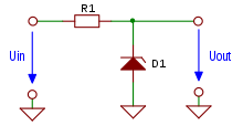
A further possibility to adapt a digital signal is a combination of a serial resistor and a parallel Zener diode . The Zener diode keeps the signal level at a defined potential and the cross current is limited by the resistor.
However, the simplicity of these level shifters has numerous disadvantages. Since these level converters work passively, it is only possible to reduce signal levels. Thus, only an information source with higher signal levels of an information sink with lower signal level can transmit information, but not vice versa.
Another disadvantage of this simple level converter is the power consumption. With a logical one, a constant current flows permanently, which causes losses.
Since the output current of this level converter is very low and each input of a digital circuit has an input capacitance, this results in a low-pass behavior . This severely limits the maximum transmission frequency .
Level converter with transistor
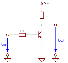
To avoid some of the aforementioned problems, a transistor can be used in combination with a pull-up resistor . The input level can be converted into any output level by connecting the pull-up resistor to a voltage source with a voltage equal to the desired output voltage.
A disadvantage of such a level converter is the cross-current that now flows at a logical zero. This circuit also inverts the signal in an emitter circuit , so it may be necessary to invert the logic signal before or after the level converter. One converter in the basic circuit (here without illustration) comparable to the next does not invert.
Bidirectional level shifter
Level converter with MOSFET
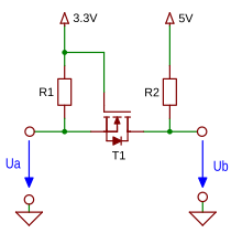
One way of building a simple bidirectional level converter is to use a MOSFET with two pull-up resistors, one of which is connected to the respectively desired operating voltage.
If a logic zero (0 V) is now applied to input U a , the source connection of the N-channel MOSFET is at ground potential . This results in a positive gate-source voltage, as a result of which the MOSFET switches through, the output U b also pulls to ground and a logic zero is applied.
If a logical one (supply voltage potential on the left side, in the example 3.3 V) is applied to U a , the source connection is at the same potential as the gate connection, whereby the MOSFET blocks. The output U b is now pulled by the pull-up resistor R 2 to the potential of the supply voltage on the right-hand side (5 V in the example), where a logical one is now applied.
If the level converter is now viewed from the other direction, a similar scenario results in the case of a logical one at the input U b . The source connection of the MOSFET is now pulled to the potential of the supply voltage on the left-hand side (3.3 V in the example) via the pull-up resistor R 1 , whereby the source and gate are at the same potential and the MOSFET blocks. At the same time, through this resistor, the potential of the supply voltage is present at the output U a , which means that this output is at logic one.
If a logic zero (0 V) is now applied to input U b , the MOSFET continues to block due to the lack of gate-source voltage. Since a discrete MOSFET, however, always has a parallel substrate diode, due to its manufacture, this now begins to conduct and also pulls the output U a to approximately ground potential (minus the forward voltage of the diode ). This now results in a gate-source voltage, the MOSFET begins to conduct and finally pulls the output Ua to ground, as a result of which a logic zero is now applied to Ua.
The prerequisite for the correct functioning of the circuit is a MOSFET whose threshold voltage is lower than the supply voltage on side A so that the transistor can switch through at all. It should also be noted that the supply voltage of side A must be lower than that of side B , since otherwise the higher supply voltage is applied via the substrate diode of the MOSFET on the other side.
Other level converters
There are level converters for almost all applications as integrated electronic circuits. In the case of bidirectional level converters, the conversion direction is usually selected by a separate control line. A clear advantage of a level converter as an integrated circuit is the cutoff frequency, which is usually significantly higher than that of a discrete circuit.
Level converters for digital signals with any output voltage can be set up quite easily with the aid of a comparator. However, here too the maximum transmission frequency is severely restricted by the limit frequency of the comparator.
In principle, each level converter can also be designed as a galvanically isolated variant. Analog level converters with galvanic isolation are very similar to an isolating amplifier, even if an isolating amplifier only amplifies the signal level and does not directly adjust (shift) it.
Interface driver
Interface drivers can be viewed as a special form of level converter. In addition to the actual adaptation of the signal level, interface drivers can also have integrated complete voltage conditioning circuits in order to be able to generate the voltages required for the output level themselves. Depending on the application, interface drivers have corresponding outputs, such as B. Output pairs for generating differential signals or current outputs for operating current interfaces .
literature
- Ulrich Tietze, Christoph Schenk: Semiconductor circuit technology. 12th edition. Springer, Berlin / Heidelberg / New York 2002, ISBN 3-540-42849-6 .
- Erwin Böhmer: Elements of applied electronics. 15th edition. Vieweg & Sohn Verlag, Wiesbaden 2007, ISBN 978-3-8348-0124-1 .


