Slide motor


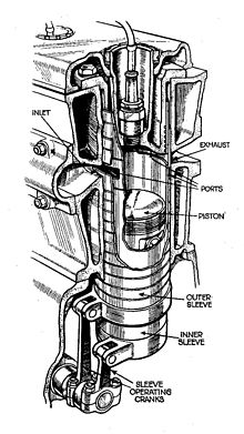
designations from top to bottom: inlet, outlet, orifices, pistons, outer and inner slide sleeves, sleeve drive cranks
Slide engine is the generic term for various types of two and four-stroke engines with slide control for the gas exchange . In contrast to valve-controlled motors, whose inlet and outlet valves are closed when closed, slide motors are controlled by means of constantly moving, circling or rotating slide valves. At the turn of the 19th to the 20th century, several manufacturers tried their hand at valve controls; with four-stroke engines, only the sleeve valve systems from Charles Yale Knight and Argyll Motors (based on Burt and McCollum) were successful until the Second World War.
The main technical problem is to maintain a tight valve closure against high compression pressure in spite of the low-friction mounting of the slides, which is made more difficult by material expansion in the event of strong temperature changes. The slides must be well lubricated, which means that oil is lost at the control edges. In valve control with poppet valves , the seal is supported by the compression pressure and the valve seat is not lubricated. Valve control is only available as an inlet rotary valve in some two-stroke engines. There the slide only has to seal against the low pre-compression pressure of the crankcase and is not exposed to any higher temperatures or temperature changes.
overview
From the beginnings of engine construction until well into the 1940s, there were various attempts to control the gas exchange (intake, exhaust) in internal combustion engines. The controls of steam engines and the fittings as operating elements of machines and devices served as models for the engine builders . The valves built into combustion engines today were often the cause of engine damage in the early days of engine construction. They often broke at the transition from the valve stem to the valve head. Other disadvantages of the valves were also evident. Many engine builders designed slide controls to avoid the disadvantages of valves. All rotary valve designs have in common the problem of tightness at high combustion pressures and high temperatures. Several concepts were developed until they were ready for series production.
With sleeve valves, the combustion pressure is absorbed by the sleeve and does not affect the joint between the valve and the housing. The seal between the cylinder head and the slide is done by piston rings, which were technically controllable even before the First World War. The American journalist Charles Yale Knight invented a control system with two reciprocating concentric slide sleeves in 1903, which were used in sports and luxury cars until the late 1930s. In 1912, the Scottish car manufacturer Argyll Motors introduced valve motors, which got by with a rotating valve sleeve and had been designed by engineers Burt and McCollum. During the Second World War, the British manufacturer Bristol produced some types of aircraft engines such as the Bristol Hercules with slide control according to Burt-McCollum in series. From BMW , Daimler-Benz and Junkers of World War II aircraft engines (a torpedo engine Junkers) with DVL-WVW-flat slide valve control have been developed for series production towards the end. However, they were no longer manufactured in series, since at that time the first jet engines , which were technically superior to all piston engines, had already been developed.
A more recent development are spherical rotary valves. The slide has the shape of a spherical section. Two slides are used per cylinder, one each for inlet and outlet. They are mounted in the cylinder head and rotate at half the crankshaft speed. The slides run on ceramic rings and do not need any lubrication.
Historical
In the early days of internal combustion engine development, innumerable variants of slide controls were designed and built. Many of them (as far as we know today) were doomed to failure from the start. Successful slide controls were only equipped with oscillating sleeve slides, which is why the following description is essentially limited to this design.
Some well-known designs are:
- with rotating slides
- Cylinder: Itala (after 1904)
- Cone: Aspin 1937
- Ball: Sklenar 1938
- Disc (flat slide): aircraft engine from BMW 1943
- with swinging (oscillating) slides, only as sleeve slides
- twofold: Knight 1908
- simple: Burt-McCollum 1911.
The first widespread valve motor was developed in Chicago by Charles Yale Knight (1868–1940) from 1903, developed to series maturity by 1907 and registered for a patent in 1908, first in Great Britain and then in 1910 in the USA.
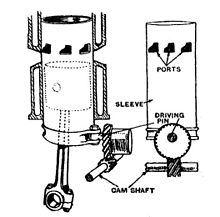
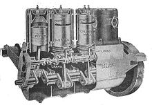
With the Knight slide control, the gas exchange is controlled via two slide bushings 3 mm thick, which are concentric to the cylinder axis and which move up and down with a stroke of around 25 mm during engine operation. The piston runs in the inner slide bushing. The sockets are driven by an eccentric shaft located in the crankshaft housing and running at half speed via short connecting rods. When the slide bushes are moved, the inlet and outlet slots are alternately released. They are opposite each other at the top of the cylinder. At the time, such slide motors were more robust and less prone to failure than valve-controlled motors and were valued for their exceptional smoothness and their good performance in the lower speed range. In this they were superior to valve-controlled motors of equal size.
However, with increasing engine power and speeds, the Knight sliders reached their limits. The relatively large and heavy slides limited the possible engine speeds and the two slider sleeves between the piston and the actual cylinder hindered the heat dissipation of the piston. In addition, there were lubrication problems with the slides.
Felix Wankel has dealt very intensively with rotary valve controls. This culminated in the development of the WVW-DVL rotary valve control for large aircraft engines (WVW = Wankel Versuchswerkstätten, DVL = German Research Institute for Aviation ).
Construction and manufacturing
Slide motors could only be manufactured with a high level of design and technical effort and their operation made high demands on regular maintenance. They used a lot of oil; A lack of oil led to irreparable damage to the engine. They were of particular interest to manufacturers of high-end cars. More than 30 manufacturing licenses have been granted for the Knight valve control, for example to Daimler (Mercedes) , Panhard & Levassor , Minerva , Hotchkiss , Laurin & Klement . Mercedes developed three engines from 1910, the most successful of which was produced until 1924.
Technical data of the Mercedes-Knight 16/45 PS:
- 4 cylinders
- Bore: 100 mm, stroke: 130 mm
- Displacement: 4084 cm³
- Power: 33 kW (45 HP) at a speed of 1300 min −1
- Top speed: 85 km / h
In the last year of production, the output was increased to 50 hp. A total of 5500 vehicles with Knight engines were built at Mercedes. In 1927, a special Voisin car equipped with a 12-cylinder Knight engine with a displacement of 8 liters set the 24-hour world record. He drove an average speed of 182.5 km / h. In 2004, a Mercedes-Knight from 1912 won the Gordon Bennett race in Bad Homburg vor der Höhe, which is supported by the AvD , in the classic car class up to 13.5 liters.
Structure of the pipe / sleeve valve
Sleeve valves are movable tubes that are installed between the piston and cylinder. They have openings which, in a certain position, coincide with matching openings in the cylinder and thus allow the intake and exhaust gases to pass through. The slides are driven at half the crankshaft speed.
With the Knight control, there are two interlocking slides that perform a back and forth movement. The control orifices are opposite slots, the outlet is opposite the inlet.
The Burt-McCollum control works with a slide that is moved on an approximately circular path. Several irregularly shaped outlet and inlet openings are distributed over the circumference of the cylinder. The slide alternately releases the exhaust and intake openings and keeps them closed during the compression and work cycle.
Aircraft engines
Gate valve engines are typically lighter and more powerful than comparable contemporary valve engines. The British manufacturers Napier & Son and Bristol Aircraft Company successfully built engines with slide controls for aircraft in series from the mid-1930s. Bristol built radial engines, Napier H engines . The Bristol Hercules was in use in the North Noratlas until the early 1970s. They had Burt-McCollum style valves.
Advantages and disadvantages
The advantage over conventional valve control in combustion engines is the continuous movement of the slide. This results in lower maximum accelerations that limit the maximum speed. Furthermore, the flowing gases are not hindered by the flow-unfavorable valve. The control cross-sections that can be achieved are also larger than with poppet valves. The straight gas flow and the short flow paths result in only slight turbulence and little heating. This benefits a significantly better filling and thus a higher engine performance. Further advantages arise depending on the design.
The higher cost of sealing the moving parts has a disadvantageous effect on the cost and durability of the system. If the operating temperatures are too high, there is a risk of the valve parts being seized or jammed.
Slide control for two-stroke engines
In almost all two-stroke engines, the piston also acts as a control slide, in large two-stroke diesel engines the inlet is controlled by the piston and the outlet by a poppet valve actuated by a cam.
However, there are also two-stroke engines with a disc-shaped rotary valve that is driven directly by the crankshaft and controls the mixture inlet into the crankshaft housing. Since the slide does not come into contact with high pressures, temperatures or the abrasive combustion gases, it is practically not subject to any wear compared to the slide in four-stroke engines.
With such an engine, Ewald Kluge became German and European champion as well as TT winner in the class up to 250 cm³ in 1938 on a DKW racing machine . Herbert Friedrich developed the rotary valve at DKW . Unlike many other top designers, he did not move to West Germany after 1945 . In the later GDR , among other things, he designed the rotary valve control for the Trabant engine, which enabled considerable torque and high elasticity of the engine. A recess in the crank arm acted as an inlet rotary valve. The intake control, which is independent of the piston position, has always been a popular point of attack for tuners . Kawasaki built smaller rotary valve two-stroke engines until the 1980s.
The same crankshafts with a recess on one of the crank webs can be found in the millions of engines in most Vespa scooters, which were produced from 1959 until the PX series was discontinued at the end of 2016.
This is where tuning comes in with these engines, which are still available in large numbers, by modifying the length and position of the incision (inlet timing) and designing the crank web to optimize flow ("lip wave"). The shaft often has to be rebalanced afterwards.
There were also two-stroke engines with exhaust rotary valves, which had advantages for gas switching (asymmetrical control diagram ), but are expensive and fragile because of the high exhaust gas temperatures. The Yamaha Power Valve System , often incorrectly referred to as an exhaust rotary valve, is a rotatable device in the exhaust duct with which the exhaust control time can be changed via the effective height of the exhaust slot depending on the engine speed, thus increasing the power range of the engine.
Dieter König from Berlin built very powerful outboard racing engines with inlet rotary valves, with which all World and European Championships in the 250 cm³, 350 cm³, 500 cm³ and 700 cm³ classes were won from 1960 to the end of the 1980s. In these two- and four-cylinder boxer engines , the rotary valve was located on the side of the crankcase and was driven by a toothed belt.
A motorcycle based on one of these engines, the König 500 GP, caused a sensation in the GP scene in the early 1970s. The motorcycle was designed and piloted by New Zealander Kim Newcombe. He knew the engines as outboard boat drives and was hired by König. Kim Newcombe managed to break the dominance of the MV Agusta with this motorcycle . In August 1973 he had a fatal accident, but was posthumously runner-up in the world championship. Today the former König works driver Norbert Schüller builds this motorcycle as a purchase kit in Langenfeld . In 2011 he presented the motorcycle at the VFV Championship at the Nürburgring and came third in his run. In the 1960s and 70s, Kreidler and Zündapp engines were also converted to rotary valve controls for racing.
literature
- Peter Gerigk, Detlev Bruhn, Dietmar Danner: Automotive engineering. 3rd edition, Westermann Schulbuchverlag GmbH, Braunschweig 2000, ISBN 3-14-221500-X .
- Max Bohner, Richard Fischer, Rolf Gscheidle: Expertise in automotive technology. 27th edition. Verlag Europa-Lehrmittel, Haan-Gruiten 2001, ISBN 3-8085-2067-1 .
- Peter A. Wellers, Hermann Strobel, Erich Auch-Schwelk: Vehicle technology expertise. 5th edition. Holland + Josenhans Verlag, Stuttgart 1997, ISBN 3-7782-3520-6 .
Web links
- About the Knight engine (English)
- Via rotating valves in internal combustion engines (English)
- Article on failed engine concepts (PDF; 1.1 MB) Prof. Stefan Zima, FH Gießen-Friedberg
Individual evidence
- ^ Rotary-Valve Internal Combustion Engines. Mechanical engineering programs. Retrieved July 7, 2019 .
- ↑ Spherical Rotary Valve System - CSRV vs. Poppet Valve. In: Website Coates Int. Ltd. 2011, accessed on May 30, 2019 .
- ↑ Internal combustion engine. April 4, 1904 ( google.com [accessed July 7, 2019]).
- ^ Peter Kirchberg: Plastics, sheet metal and planned economy . Page 178. Nicolai-Verlag, Berlin 2000, ISBN 3-89479-259-0 .


