Three phase rectifier
Three-phase rectifier , also three-phase rectifier , are electronic rectifier circuits , the three-phase alternating current into direct current converter. They are primarily used in the field of electrical power engineering for medium to high-power output, for example to supply direct current operated trams from the three-phase alternating current supply network , for three-phase alternators in motor vehicles or in the form of extended inverters in the high-voltage direct current area -Transmission (HVDC).
Three-phase rectifiers have a lower ripple voltage than rectifiers for single-phase AC voltages due to the fact that they are fed in with three phase-shifted AC voltages with otherwise the same power and filtering . Further advantages are the more sinusoidal input current compared to single-phase rectifiers and the resulting low load on the supply network with distortion reactive power and the lower harmonics .
General
In order to keep the ripple voltage on the DC voltage side low, smoothing capacitors and storage chokes are used as in the single-phase AC voltage rectifiers . For the use of certain three-phase rectifiers, three-phase AC transformers , which are functionally connected to the circuit, are required in some circuits . In the field of energy technology such as HVDC systems, these transformers are also referred to as "converter transformers".
The Vienna rectifier is an extension of the three-phase rectifier with a combined switched-mode power supply to reduce the harmonic component and simulate the sinusoidal current curve on the AC voltage side .
Types
Three-phase rectifiers can be set up as midpoint or bridge circuits (three-phase bridges). The further subdivision is made by the so-called pulse number. This indicates how many rectifier branches become conductive within a period . Rectifier circuits with the highest possible number of pulses reduce the ripple voltage, but the circuit complexity increases with a higher number of pulses. The residual ripple is calculated from the ratio of the alternating voltage superimposed on the direct voltage (as rms or peak-valley value ) to the respective rectified value :
| circuit | Rectified value | Rectified value ( low voltage network) |
AC component (effective value, low-voltage network) |
Ripple (from rms value) |
Alternating portion (peak-valley value, low-voltage network) |
Fluctuation ripple ( from peak-valley value) |
Frequency of the alternating component |
|---|---|---|---|---|---|---|---|
| M3 (three-pulse) | 1.170 | 269 BC | 115 V | 42.8% | 163 V | 60.5% | 3 × |
| B6 (six-pulse) | 2,339 | 538 V | 53.4V | 9.5% | 75.5V | 14% | 6 × |
| B6-2S (twelve pulses) | 4.678 | 1076 V | 10.8V | 1.0% | 36.6V | 3.4% | 12 × |
Midpoint connections
Uncontrolled three-pulse midpoint switching (M3U)
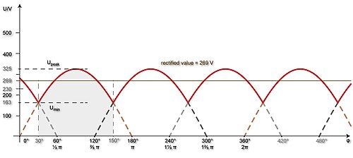
The uncontrolled three- pulse mid -point connection is similar to the two-pole bridge rectifier (B2U) and is the simplest three-phase rectifier (also known as three- pulse rectifier). The cathodes of three diodes form the positive pole, the neutral point of the secondary winding of the transformer (when operating on mains voltage, the neutral conductor of the power supplier) the negative pole. In all phases, only the positive half-oscillation is used and their sum is used as a pulsating DC output voltage. Disadvantages are the high residual ripple (60.5% without filter capacitor) and their low frequency (three times the mains frequency).
The peak values of this three-pulse direct voltage (325 V with direct operation on the low-voltage network ) are calculated from the respective effective value or the phase voltage of the three half-waves (230 V with direct operation in the low-voltage network) . The arithmetic mean of the rectified voltages or the ideal rectified value results from the integral under the graph of a positive half-wave with the period duration (from 30 ° to 150 °):
- ⇒ ⇒ ≈ 1.17 ⋅
With direct operation of the three-pulse mid-point connection in the low-voltage network, a rectified value of 269 V results.
Controlled three-pulse center point switching (M3C)
The controlled three-pulse mid-point circuit (C for controlled ) is implemented with three thyristors , which enable voltage regulation via phase control (similar to a dimmer ).
Six-pulse midpoint switching (M6)
In the past, the six-pulse mid-point circuit was used in particular for multi-phase mercury vapor rectifiers with six anodes. Since all cathodes are at the same potential, they can be structurally combined into a common cathode in the mercury vapor rectifier. The M6 rectifier can be constructed by connecting two M3 circuits in parallel to a phase swivel transformer with six secondary windings, which is connected in a star connection on the secondary side. The rectification value is then calculated using the formula:
- ≈ 1.35 ⋅
Another circuit design was the center tap on the three-phase transformer:
Three-phase bridges
The three-phase bridge is a type of bridge rectifier and uses both half-waves of a phase cycle for rectification. The three-phase bridge is the most common form of three-phase rectifier, whereby the secondary windings of the transformer are again linked in a star connection (if the circuit is not operated directly on the mains). In contrast to the M3U circuit, the star point is not connected to the three-phase bridge, insofar as the currents only flow between the outer conductors .
Uncontrolled three-phase bridge (B6U)
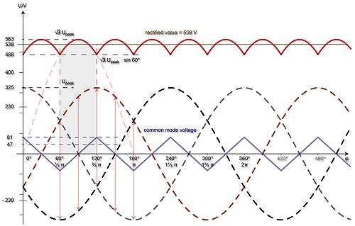
The uncontrolled three-phase bridge or six-pulse bridge circuit is implemented with six power diodes and, in simplified terms, can be understood as a series connection of two three- pulse midpoint circuits. The pulsating DC voltage results from the differences between the momentary positive and negative external conductor voltages (phase voltages), the pulses of which are phase-shifted by 30 °:
The rectified value results from the integral under the graph of a DC voltage pulse with the period duration (from 60 ° to 120 °) with the peak value :
- ⇒ ⇒ ≈ 2.34 ⋅
When the six-pulse bridge circuit is operated directly in the low-voltage network, this results in a rectified value of 538 V. The peak values of the six-pulse direct voltage (e.g. 563 V) result from the peak values of the line voltages (e.g. 325 V) and that of a three-phase system own chaining factor :
- ⇒
Common mode voltage
If the bridge circuit is operated symmetrically, i.e. as a positive and negative supply voltage, the output-side center point of the bridge circuit or the isolated reference potential has a potential difference in the form of a triangular common-mode voltage compared to the center point of the transformer (or the neutral conductor) . For this reason, the two center points must never be connected to one another, otherwise short-circuit currents would flow. The mass of the bridge circuit is therefore decoupled from the neutral conductor or earth . When operating on the transformer, earthing of the center point of the bridge circuit is possible, provided that the secondary winding of the transformer is galvanically isolated from the mains supply and the star point of the secondary winding is therefore not on earth. In this case, however, (negligible) leakage currents flow through the transformer windings.
The common-mode voltage is formed from the respective instantaneous mean values of the differences between the positive and negative phase voltages, which form the pulsating direct voltage. The peak value of the triangular voltage is ¼ of the peak value of the phase voltage (325 V for mains voltage) and is calculated from minus half the DC voltage at 60 ° of the period:
- = 0.25 ≈ 325 V 0.25 ≈ 81 V
The rms value of the common mode voltage is calculated from the form factor for triangular waves:
- ≈ ≈ 47 V
If the circuit is operated asymmetrically, i.e. as a simple supply voltage with a positive pole, both the positive and negative pole (or the isolated reference potential) pulsate in relation to the center point (or ground) of the feed, analogous to the positive and negative peaks of the string voltages . The peak value of the pulsating voltage of a pole to earth is half of the peak value of the string voltage (i.e. ≈ 163 V on the mains), the rms value to earth is half the string voltage (115 V on the mains). However, the differences in the phase voltages result in the six-pulse direct voltage (over the duration of one period). The strict separation of the transformer center point from the negative pole (for other short-circuit currents) or a possible grounding of the negative pole when using an isolating transformer apply according to the symmetrical wiring.
B6U with 12 diodes
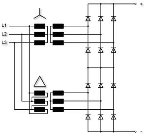
Two B6U rectifiers can be operated on the three individual secondary windings (shown as voltage sources in the picture) of a three-phase transformer. The diodes of this circuit can also be implemented in the form of three Graetz bridges . If the transformer windings have center taps, they can be used to obtain a midpoint of a symmetrical output DC voltage.
Half-controlled three-phase bridge (B6H)
The half-controlled three-phase bridge (B6H) is constructed with the cathodes of three thyristors on the positive pole and the anodes of three power diodes on the negative pole.
Controlled three-phase bridge (B6C)
The fully controlled three-phase bridge B6C (or six-pulse bridge circuit), which is mainly used for large loads up to over 10 megawatts, is implemented with six thyristors that enable voltage regulation via a gate control, for example for the stepless speed control of DC motors.
Twelve pulse rectifier
The twelve-pulse circuit is fed via a phase swivel transformer with six secondary windings, whereby the (primary or secondary) turns of one bridge according to the star-star principle and those of the other bridge according to the star-delta principle to generate the phase shift between the two bridges are switched. The voltages between the outer conductors of a three-phase system or the triangular voltages are basically phase-shifted by 30 ° compared to the phase voltages. The turns ratios of the transformer must be designed in such a way that the various voltages of the star or delta connection are balanced.
The advantages of the twelve-pulse circuit are the low residual ripple in rectifier operation and the low harmonic content in inverter operation. In particular, only harmonics with frequencies twelve times the frequency of the mains frequency occur (at 50 Hz mains frequency this is 600 Hz). The twelve-pulse circuit can be set up with two B6U rectifiers in series or parallel connection:
- In a series connection , also known as a B6-2S circuit, the output voltage is doubled, the current intensity of the circuit corresponds to the current intensity of the individual bridges:
- In parallel connection , also called B6-2P connection , the output current is high, the output voltage corresponds to the voltage of the individual bridges:
The twelve-pulse circuit is used to supply high-voltage direct current consumers such as electron tubes in transmission systems. It is used almost without exception in high-voltage direct current transmission systems, as it results in low residual ripple and thus reduces the effort required for the harmonic filters operating at high-voltage potential. The diodes are implemented by thyristors or IGBT , which enables operation as a rectifier or inverter .
Higher pulse rectifiers
The 18-pulse and 24-pulse rectifiers are an unusual extension. In both cases, three secondary-side three-phase windings are required, which add up to form three-phase voltage systems offset by 20 ° or 15 °. The amounts or the number of turns on the secondary side must be coordinated with one another. Because of the greater complexity of circuitry, these forms are only of secondary importance.
literature
- Rudolf Busch: Electrical engineering and electronics: for mechanical engineers and process engineers . 4th edition. Vieweg + Teubner, 2008, ISBN 978-3-8351-0248-4 .
Individual evidence
- ↑ Ralph Kennel: Power Electronics, Basics and Standard Applications. (PDF; 1.4 MB) TU Munich, accessed on January 10, 2017 .
- ↑ Hans-Ulrich Giersch, Hans Harthus, Norbert Vogelsang: Electrical machines . Springer-Verlag, May 27, 2003, p. 66 .
- ↑ limited preview in the Google book search
- ^ Rudolf Busch: Electrical engineering and electronics . Springer-Verlag, September 9, 2015, p. 247 .
- ↑ limited preview in the Google book search
- ^ Dierk Schröder: Power electronic circuits . Springer-Verlag, July 23, 2008, p. 89 .
- ↑ limited preview in the Google book search
- ^ Wolfgang Courtin: Electrical energy technology . Springer-Verlag, July 2, 2013, p. 250 .
- ↑ limited preview in the Google book search
- ^ Joachim Specovius: Basic course in power electronics . 4th edition. Vieweg + Teubner, 2010, ISBN 978-3-8348-1307-7 , pp. 174 .
- ↑ limited preview in the Google book search


![{\ displaystyle {\ overline {u}} = {\ frac {1} {{\ frac {2} {3}} \ pi}} \ int _ {30 ^ {\ circ}} ^ {150 ^ {\ circ }} {\ hat {u}} \ cdot \ sin \ varphi \ cdot \ mathrm {d} \ varphi = {\ frac {3 {\ hat {u}}} {2 \ pi}} \ cdot \ left (- \ cos 150 ^ {\ circ} + \ cos 30 ^ {\ circ} \ right) = {\ frac {3 {\ hat {u}}} {2 \ pi}} \ cdot {\ Biggl [} - \ left (- {\ frac {\ sqrt {3}} {2}} \ right) + {\ frac {\ sqrt {3}} {2}} {\ Biggl]} = {\ frac {3 \ cdot {\ sqrt {3}} \ cdot {\ hat {u}}} {2 \ pi}}}](https://wikimedia.org/api/rest_v1/media/math/render/svg/73282681e5efef8034615f594111fc8b8a2f91ac)


![{\ displaystyle {\ overline {u}} = {\ frac {1} {{\ frac {1} {3}} \ pi}} \ int _ {60 ^ {\ circ}} ^ {120 ^ {\ circ }} {\ sqrt {3}} \ cdot {\ hat {u}} \ cdot \ sin \ varphi \ cdot \ mathrm {d} \ varphi = {\ frac {3 \ cdot {\ sqrt {3}} \ cdot {\ hat {u}}} {\ pi}} \ cdot \ left (- \ cos 120 ^ {\ circ} + \ cos 60 ^ {\ circ} \ right) = {\ frac {3 \ cdot {\ sqrt {3}} \ cdot {\ hat {u}}} {\ pi}} \ cdot {\ Biggl [} - \ left (- {\ frac {1} {2}} \ right) + {\ frac {1 } {2}} {\ Biggl]} = {\ frac {3 \ cdot {\ sqrt {3}} \ cdot {\ hat {u}}} {\ pi}}}](https://wikimedia.org/api/rest_v1/media/math/render/svg/5f683356b9a1556d025cfc79b4a2f73e287c3649)


