
Schäferkämper watermill
The Schäferkämper watermill is a flour mill on the southern outskirts of Bad Westernkotten , a district of Erwitte in North Rhine-Westphalia. The mill is powered by the water of the Osterbach , which rises about one kilometer above the mill. It has two overshot water wheels that drive two grain grinding gears. The mill was built in 1748, the commercial grinding operation lasted until 1933. After the death of the last owner in 1989, the mill was acquired by the North Rhine-Westphalia Foundation, restored by Heimatfreunde Bad Westernkotten with the support of the foundation and set up as a museum . Both grinders are ready for use. Every Saturday is the grist mill taken at the regularly scheduled mill lead in operation.

history

Location of the mill (marked with a red star) |
origin
In 1746 the residents of Westernkotten presented to the Archbishop of Cologne and expressed their wish to be allowed to build a mill. Archbishop Clemens August was not only Archbishop of Cologne, but also of Munster, Paderborn, Osnabrück and Hildesheim and thereby also sovereign . His privileges included the right to dam and mill . He granted the request and put the construction and operation of the mill out to tender. The contract was awarded Count Wenzel Anton von Kaunitz-Rietberg for an annual license fee of 140 Reichstalern . After he had received the bid, he had to find a suitable location in Westernkotten and negotiate the acquisition of the relevant property. On May 14, 1748, an extensive contract was signed in Westernkotten between representatives of the count and the community of Westernkotten. The notary Franz Wilhelm Pollmann and two witnesses were present. Four essential points were defined by the contract:
- The Count's representatives paid 350 Reichstaler in cash for the land purchase.
- The parcel is measured by a sworn land surveyor before the eyes of the contracting parties and separated by boundary stones.
- The count undertakes not to build a house near the mill, only a stable. In addition, he undertakes not to "flood" too high a farm road above the mill pond.
- The community representatives undertake to have their grain ground exclusively in the mill. This was confirmed on the contract with 67 signatures, so these farmers submitted to the so-called mill compulsion .
In this document, the sovereign also promised the count not to allow any further mills in Westernkotten within a radius of one hour and on the banks of the Osterbach. This is known from the Middle Ages and the early modern period ago Mill spell also included the provision that all the farmers of this spell district to a mill their grain could be ground only in this mill, whether another mill was closer, the quality was better or the wage less.
These provisions - mill compulsory and mill ban - were to be taken seriously. From today's perspective, disproportionate penalties were disproportionately high. The already common and applied penalties, for example the ex officio confiscation of field crops and flour, were tightened again in 1758 by Archbishop Clemens August.
- Historical views of the mill

Front view of the mill with staff
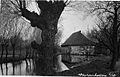
View from the east, in the foreground the Osterbach

The owners at the beginning of the 20th century: the Thiemann family
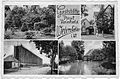
The mill as part of a historical postcard from Bad Westernkotten (bottom right) The other pictures show: part of the spa park, restaurant, graduation tower (ul)
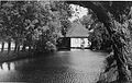
View from the east, in the foreground Osterbach and Mühlteich


Changing ownership and ownership
After the mill was built, it was operated by the Count of Kaunitz-Rietberg's workers for about 20 years. Their names are not known. The mill was only leased from 1767. The first tenant, Franz Conrad Schnitger, signed the six-year lease on August 12, 1767. He extended the lease three times for six years each time. He died on April 6, 1787 in Bökenförde , a neighboring village of Westernkotten. His wife apparently continued to run the mill and extended the lease again on March 18, 1791, but only for three years. This time the lease was advertised publicly, the woman had to prevail against a number of competitors. She also had to leave a deposit of 300 Reichstalers. Obviously she could not hold the mill, because the lease was put out to the public again as early as the next year. From the crowd of applicants, Müller Vogel, Eikenbusch and Falkenstein were awarded the contract for three years. 1795, when it was extended, Vogel and Eikenbusch were awarded the contract for a further six years.
modernization
Around 1900 the order situation for Schäferkämper Mühle was so good that water power alone was no longer sufficient. After about three hours of eating, it was necessary to wait eight hours each time until the mill pond was filled. The owner Ludwig Thiemann acquired a locomobile , a mobile steam engine, and modernized the mill by converting it into a steam mill, creating the additional option of grinding independently of the water power. The steam engine was fired with wood or coal. This machine stood outside the actual mill building, where the annex is today. The power of the locomobile was fed via belt drives to the vertical shaft of one of the two grinding aisles.
A few years later the steam engine was replaced by an electric motor . Thiemann was one of the first to use an electrical unit in Westernkotten.
At the turn of the 20th century, the elevators were already installed, combined with the transmission drives that became necessary . The classifier was also installed during this period - perhaps by 1910 at the latest . Its supplier was Atorf & Propfe from Paderborn, a specialist in milling technology. The exact timing of the fixtures can no longer be determined.
Other modernizations cannot be proven and were probably of a rather minor nature.
building

The mill building is built on two floors from rubble stones . The walls are up to 1.70 m thick, plastered and square on the outside at the corners. The hipped roof is covered with clay tiles. In the middle above the entrance there is a roof house with an elevator. In the building, the mill and miller's apartment are united under one roof, a fact that, according to the Westphalian Museum Office, gives the Schäferkämper watermill its unique status. In the monument value statement of December 12, 1989, it says: "... a combination that is currently no longer known in the area of the Soest district in this completeness". The interior construction consists of timber frame walls and wooden beam ceilings. The heavy mechanics of the mill are supported by massive oak beams.
The grain mill extends over four floors, the cellar with the inner axle bearings of the mill wheels and the angular gear, the ground floor - the so-called grinding stage - with the millstones and the bag filling, the first floor - the classifier floor - with grain storage, classifier and transmission distribution and the attic as a drying floor with sack elevator and deflection for the bucket elevator .
The right extension used to be used as a pig stall , toilet and location for the traction engine. Today the kitchen and the sanitary facilities for visitors are located there.
Miller's apartment

Viewed from the entrance, the miller's apartment was directly to the left, i.e. also to the left of the workroom and grinding chair. It had a separate entrance from the work room and was therefore completely separated from the operating rooms as a residential unit. The small kitchen is on the ground floor and leads to the living / dining room. A living room adjoins, from which a staircase leads to the sleeping area on the first floor.
In the opinion of the Museum Office and the Monument Office, the miller's apartment should be viewed as an accessible document of contemporary and social history and presented to the public accordingly.
The little usable furniture that was found when the home friends took over the mill in 1991 was subsequently supplemented with furniture from the home friends' inventory as well as donations and loans from the local population, so that a miller's apartment in the style was possible 1930s set up.
The phrase “in the style of the 1930s” was chosen after consultation with the Westphalian Museum Office, because the Thiemann family's bedroom, which was found in its entirety, dates from this period. The living room cupboard , a softwood chest of drawers and the small Biedermeier table also belonged to the Müller family. However, this furniture was in a very poor condition, which made costly restoration necessary. The numerous everyday objects have been donated over the years.
Mill technology
Water wheels and drive shafts


For two separate current millstones ( shot and fine flour ), the mill is provided with two overshot waterwheels equipped. They each have a diameter of 3.20 m, a width of about 80 cm and carry 32 or 36 water scoops . Today's water wheels are reconstructions based on drawings from 1923. The wheels are made of oak , and the blades of both wheels were originally made of oak. At the turn of the 19th and 20th centuries, metal blades were used on a wheel. This state can be seen again today.
Why a separate water wheel was installed for each of the two grinding stages can only be guessed due to the lack of documents. It is probably related to the range of services offered by the water of the Osterbach. With the low water supply in the summer months, at least one grinding course could be operated for a long time. The sifter installed later (around the end of the 19th century) also meant that a minimum speed had to be observed. Switching off a grinding process was easier thanks to the independent drives.
The average power achieved per wheel is around 4.5–5.9 kW (6–8 hp ). The torque of the water wheels is transmitted to the inside of the mill via octagonal shafts . The waves are made of oak logs with a diameter of about 50 cm.
Both shafts are mounted both outside and inside the cellar with stone bearings (granite), and they are lubricated with beef tallow.
In the picture of the corner gear, starting from the massive horizontal bar in the middle of the picture, the mill iron going vertically upwards can be seen. The pinion is disengaged so that nothing is driven in spite of the rotating mill wheel. The massive iron bar on the left is part of the light work for raising and lowering the runner stone. The cattle valley reservoir for the bearing lubrication can be seen in the front under the small wooden cover.
Grinding mills

Grinds are the heart of every grain mill. Like most mills in the Westphalian region, the Schäferkämper Mühle also has two grinding stages, one for feed and baking meal and a second with a downstream sifter for fine flour. They are arranged on the "Mahlbühne" or "Mahlstuhl", with a view of the entrance door to the right of the flour milling process, to the left the grist milling process.
The power to drive the respective grinding process is transmitted from the water wheel shaft to the vertical mill iron via the corner gear in the basement . This has the task of storing the upper millstone, which is also called the runner stone, i.e. taking up its weight and keeping it in suspension, and turning it into the rotation set by the water wheel.
The grinding aisles are on the ground floor of the mill on the mill frame - the grinding chair - a sturdy substructure made of oak supports , thresholds and beams. This oak construction is located above the two angle drives and has its own natural stone foundation.
Lichtwerk
The lightworks, with which the miller could adjust the clear distance between the two millstones with millimeter precision, is part of every grinding process. This was necessary in order to be able to set the correct degree of grinding of the flour. In order to be able to lift the heavy load of the mill wheel, mill iron, bearing point, belt wheels and framework, a triple leverage (1: 2; 1: 1.3; 1: 1.35) has been implemented in the basement. This is moved from above from the grinding platform directly next to each grinding process with a hand crank with a transmission ratio of 1:33. So it is possible to lift the weight of about 1500 kg on the crank with a hand force of about 130 Newtons . The flat pitch of the spindle thread results in an effective self-locking effect when lowering the weight.
Millstones
Each grind has two millstones on top of each other. The lower one is called the bearing stone or floor stone . It is firmly anchored on the mill stage . Its absolute horizontal position can be adjusted with three screws. The Oberstein, also known as the runner , can be changed in its distance to the bearing stone. This allows you to set how “sharp” the shot is ground.
The stones on the left hand side have a diameter of 1.50 m, on the right side it is 1.30 m. The millstones are made of sandstone , with three of the original millstones being used again during the renovation.
The furrows in the grinding surfaces of the upper and lower stone are called millstone sharpening and have the task of crushing the ground material, transporting it to the edge and supplying fresh air for cooling.
Bucket, vibrating shoe and trunk funnel
The entire grinding process takes place between the grinding stones, covered by a wooden hood. This vat serves as a dust-tight seal. Grain is fed from above through the so-called hull funnel into the middle of the Oberstein. A vibrating shoe below the hopper opening ensures that the grain flows in evenly. Incidentally, it is the component that makes a grinder rattle . The height of the grain flow conveyed through the vibrating shoe can be varied by the miller changing the inclination or the amplitude of the vibrating movement. The conveyed grain falls from the vibrating shoe through the grinding lye and gets through the so-called sip between the millstones, where it is ground. The ground material falls out between the stones on the sides and either collects in a tied-up sack or is fed to a further refinement via an elevator mechanism.
Elevators and transmission belt drives

Before the invention of the elevator , the grist fell into a tied-up sack that had to be changed when it was full. Elevators have been around since the end of the 18th century. Elevators were probably not installed in the Schäferkämper Mühle until the turn of the 20th century.
This is a rotating bucket elevator, in which - here in the present example - buckets were riveted to a belt at a distance of about 30 cm. The belt itself is hidden in a wooden pipe shaft and is driven by a transmission belt, which in turn is driven by the mill wheel. At both grinders of the Schäferkämper Mühle, after the grinding process, it picks up the grist where the flour sack used to be. At the right grinder, which was structurally prepared for the production of flour, the grist is transported from the elevator over three floors to the attic. At the highest point of the elevator, the buckets empty the contents into a pipe shaft, which in turn leads one floor below to the separator floor. The sifter is located on this . The elevator is driven by a transmission belt on the separator floor.
No sifter is necessary on the left-hand grinding course - the grist - because the bran remains in the flour. Here the ground material is only transported with the elevator up to the grinding platform, where it can then be sunk. So here the transmission belt drive could be made much simpler.
Sifter

The sifter in the Schäferkämper watermill is a so-called basket sifter. The manufacturer of the device was the company Atorf & Propfe , based in Paderborn, the year of manufacture can no longer be determined, but the installation is likely between 1900 and 1910. The "basket" is a wooden frame on which a fine-meshed gauze - like fabric was stretched. It lets the fine components of the grist - the flour - through, but holds back the coarser parts - the bran. Inside the sifter there is a rotor that is driven by the above-described transmission belt and works at a speed of around 400 rpm. So-called beaters are arranged on the rotor, which hurl the ground material against the sieve, the finer parts penetrate through the sieve covering to the outside, the coarser parts are thrown into the rear part of the jacket by the slightly inclined position of the beaters. There they fall through an opening into a pipe shaft, which in turn leads them one floor lower so that they can sink there. If the speed is significantly lower than 400 / min, the centrifugal force applied by the rotor is no longer sufficient to throw the flour through the sieve in a satisfactory amount. The flour that has penetrated the gauze is conveyed by a screw conveyor to the opposite end of the classifier and there falls through another pipe shaft into a flour box. The sieve frame with the gauze covering can be removed to change the covering and to clean the machine.
The term “sifter” for this type of finishing machine is historically justified, if actually wrongly chosen. Under classifiers are Klassiergeräte understand the work about the principle of current classification. Originally, however, the grain millers used simple fabric sacks or later frames covered with fabric with evenly spaced openings that were suitable for holding back the pods and husks . A classification in the sense of "division into size classes" could not be carried out with it.
Freight elevator

The freight elevator is installed in the top floor of the mill and enables material to be transported between the floors from there. This can be done either outside the building or inside through floor hatches.
It is driven by the mill iron (central drive shaft) of the fine grinding process, which is extended to the attic. The rotation is guided horizontally via a cast iron bevel gear and slowed down in a ratio of 2: 1. A belt drive (1: 2) brings the movement over a distance of about 2 m to the winding shaft of the load chain. The transmission belt is dimensioned for full slip and is tensioned manually by means of a cable pull with a pressure roller. The lifting process can be started and slowed down gently on this control rope. The lifting of loads takes place at about 1 m / s. A controlled lowering of the elevator is not possible. Here the chain must be pulled down in the disengaged state.
In order not to have to idle the elevator gear unnecessarily during pure grinding operation, the upper part of the mill iron, which is only inserted, can be raised and lowered with a simple rope winding.
literature
- Bad Westernkotten. A home book, Lippstadt 1958
- Boedeker et al. a .: The development of the Lippstädter mills , no year (approx. 1900) (Lippstadt City Archives)
- Czychowski, Prümm: Wasserrecht NRW , Cologne 6th edition 1989
- Berghaus, Kessemeier: Cologne-Westphalia 1180-1980. State history between the Rhine and Weser Lengerich 1980, on behalf of the LWL
- Lamprecht, Karl: There goes a mill wheel in: Heimatblätter (Der Patriot), vol. 19, nos. 10 and 12
- Mager, Meißner, Orf: The cultural history of the mills , Tübingen 1989
- Marcus, Wolfgang u. a. (Ed.): Bad Westernkotten. Old Sälzerdorf am Hellweg , Lippstadt 1987
- Schmoekel, Hermann: The mills in the Soest district , in: Soester Heimatkalender 1932, pp. 17-23
- Schriek, Franz: Schäferkämper mill. Structural report / repair , Lippstadt 1991
- Watermills in the Soest district . In the Kalendarium des Kreisheimatkalender 1987, ed. v. Soest district, pp. 10–37
Unprinted sources
- Soest district archive, files A 677 and A 678
- Archive Hof zur Osten, files 18-20, 29, 30, 41, 49, 67, 68 and 110 of the provisional directory (Westphalian Archives Office)
- Church book archive of the Archdiocese of Paderborn, holdings Bökenförde and Erwitte (19th century)
- Archive of Heimatfreunde Bad Westernkotten eV, archive material on the Schäferkämper Mühle from the estate of Ms. Lina Thiemann
- Archive Schloss Eggeringhausen, Acta concerning Hof zur Osten, mills and their replacement, III B, depart. 3 p.m., compartment 6
Newspapers
- The Patriot of February 20, 1938; March 5, 1938; July 4, 1951; July 21, 1990
Web links
- Schäferkämper watermill on www.erwitte.de
- Friends of home Bad Westernkotten: Schäferkämper watermill
- Westphalian Museum Office
Coordinates: 51 ° 37 ′ 34 " N , 8 ° 22 ′ 4" E