
water wheel


A water wheel , often also called a mill wheel , is a water power machine that uses the potential or kinetic energy of the water to drive all types of water mills , generators for small water power stations , water pumping stations or machines .
meaning

In many industrialized regions today, water wheels are hardly of any economic importance. Most of them are in the numerous mills that have been converted into museums, some drive smaller generators and are used to generate electricity . Sometimes water wheels only run for decorative purposes without using energy. In the Nymphenburg Palace Park in Munich, however, water wheels have operated the pumping stations for the two fountains in front of the palace for over 200 years . An important difference between waterwheels and turbines : waterwheels can run without control and with strongly fluctuating water volumes without any significant loss of efficiency . The drive energy then generated by the water wheel varies accordingly.
In addition to the pure water mills, there were and are mills that get their driving power from the simultaneous combination of water and wind energy . One of the few mills of this type still completely preserved today is the Hüvener Mühle in northern Emsland .
Most of the water wheels are available in developing countries in Africa and Asia as indispensable tools, especially for agriculture . According to reliable estimates , the power potential of waterwheels available worldwide is likely to be in the range of a few terawatts . Typically, a waterwheel provides drive power in the one to two-digit kilowatt range. It makes a contribution to the sustainable use of hydropower, as it only requires a small intervention in nature due to its low power and decentralized arrangement.
history


The mill, dating from the 3rd century AD, is the first known machine to work with a mechanism consisting of a crankshaft and connecting rod .


The invention of the water wheel by Greek engineers in the 4th / 3rd centuries. Century BC Chr. Represented a milestone in the development of technology, since mechanical energy could be made usable through the use of water power. In the beginning, water wheels were used for irrigation in agriculture, as a bucket wheel for lifting water. Such bucket wheels have been widespread in the Hellenistic states and the Roman Empire since before the turn of the ages, and later also in India and China .
Water wheels were also used to drive grinding mills in Roman times . The Roman builder and engineer Vitruvius describes in his "architectura" from the 1st century BC Both the principle of the water wheel and that of the mill in detail. The earliest evidence of a watermill in Germany came from the archaeologists through the excavation of a mill from the time of Christ's birth on the Inde . Finds in the Alemannic settlement Mittelhofen near Lauchheim date from the 6th century. There were many mills in central France as early as the 9th century. Watermills had been common in Central Europe since the 12th century. Later the use of oil mills , fulling mills , sawmills , hammer mills , paper mills and grinding mills was added. At the beginning of industrialization, the water wheel was used to drive machines through the first transmissions . They were also used in the mining industry for transporting materials and for drainage. In the Upper Harz mining industry, lead, copper and silver mining, which had come to a standstill due to the plague of 1348, was resumed at the beginning of the 16th century. In 1868 Alfred Dumreicher published a detailed description of the Upper Harz hydropower system. In it he lists 190 water wheels ranging in size from 6 feet (= 1.7 m) to 40 feet (= 11.5 m) in diameter. There are also three water column machines, which were very modern for the time . 18 water wheels are more than 10 meters in diameter and 10 water wheels are 11 meters in diameter or more. Dumreicher puts the performance achieved in this hydropower system at 1870 horse power net. Here the hydropower was used for the special requirements of ore mining. One of the most important tasks was the extraction of the ore from the underground mining tunnel over heights of sometimes more than 500 meters to the surface. At that time, a cage filled with ore weighed 300-350 kilograms. Further tasks were the transport of the miners with the help of the art of driving and the lifting of the water that seeped into the pits in the form of the water art used by miners .
Another example are the nine historical water paddle wheels still in existence in Möhrendorf an der Regnitz , which are documented as early as the 15th century. One of the largest historical waterwheels in Germany is 9.6 m in diameter, the "Big Wheel" built in 1745–1748 in Schwalheim near Bad Nauheim . It drove the mechanical pumps of an early industrial salt works . The largest water wheel of all is on the Isle of Man . The Great Laxey Wheel is about 22 m in diameter and was used to drain a mine.
A sufficient water supply was an important point in the location assessment of the emerging factories, in contrast to other location criteria today. An essential point to be able to operate a water wheel was the water rights . So today you can still find property rights of old industrial companies in the headwaters of rivers or larger streams that are no longer used by the owners. The mill dams built to improve and secure the mill's performance are often still preserved as mill ponds on small bodies of water. They had far-reaching effects on larger bodies of water and were therefore a political issue in the Middle Ages.
Towards the end of the 19th century, the emerging water turbines made it possible to use much larger amounts of water and higher gradients. With the introduction of electricity, the energy no longer had to be transmitted mechanically on site, but could be converted into electricity. Hydroelectric power plants emerged which, due to their size , could produce more cheaply and gradually replaced the small power plants with water wheels. Attempts to replace the comparatively small waterwheels with turbines failed in many cases because the two drives have completely different properties. Modern turbine developments meanwhile open up new possibilities of use.
Types of water wheels

Water wheels can be classified according to the type of water inlet. Different water wheels are used depending on the gradient and the difference in height between the inlet and outlet.
Regardless of this, a distinction is made between a cellular wheel and a paddle wheel.
- Cell wheels consist of containers (cells) that are closed at the side and at the bottom, which hold the water for a maximum of half a turn. This design is also referred to as a rod or crown wheel. A special form is the Panster wheel, which is constructed according to the same principle, but is much larger and wider and therefore suitable for use in rivers.
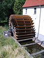
- Bucket wheels have no cells, but only radially arranged sheets or boards (blades) that are open on all sides. To keep the water in the paddles, most paddle wheels run in a goiter channel. In order to achieve a high level of efficiency, the crop flume must lie as close as possible to the shovel (see Fig. "Medium-sized water wheel"). This design is also known as a screwdriver or stilt wheel.
The images "overshot water wheel" and "medium-sized water wheel" show a cell wheel, the illustration "undershot water wheel" shows a paddle wheel.

.JPG)
Overshot waterwheel
Cell wheels are used for overshot waterwheels. The water flows through a channel (so-called channel or fluder) or a pipe to the apex of the wheel, there falls into the cells and sets the wheel in motion through its weight and kinetic energy ( impact water ). The drop height is usually between three and ten meters. Overshot water wheels have been known since the 13th century.
In contrast to a water turbine, an overshot water wheel does not need a rake to filter out floating debris, and its efficiency is less dependent on fluctuations in the amount of water. The area of application is for slopes of 2.5 m to 10 m and water volumes of up to 2 m³ / s (typical slopes of 3 to 6 m and water volumes of 0.1 to 0.5 m³ / s). The typical water wheel outputs for mills are between 2 and 10 kW. Overshot water wheels are operated at circumferential speeds of approx. 1.5 m / s.
The water is branched off from the Mutterbach at a small weir a few 100 m above the waterwheel and led to the bike in an artificial canal with little incline. This canal is often referred to as Obergraben, Mühlbach or Oberer Mühlgraben. The weir is used to regulate the amount of water flowing in. The last part of the canal before the wheel is called the flume. It is often made of wooden boards or metal. A free floodlight, also called empty shot, is attached to the channel, which guides the water past the wheel when the water wheel comes to a standstill. Another type of facility consists in widening the upper ditch into a reservoir . The water wheel is in the immediate vicinity behind the pond dam. With this type of system, the water flow to the wheel is controlled by a wheel gate, which is located at the end of the channel.
- Overshot water wheels

Channel and overshot water wheel of the Zschonermühle in Dresden

Water wheel of a Lesachtaler mill ( Carinthia , A)
Overshot waterwheel in operation (video)
.jpg)


Sweeping wheel

The sweeping wheel is a special design. It is only subjected to overshot pressure and has two oppositely arranged blade rings so that it can change its direction of rotation depending on the pressure applied. Sweeping wheels were used in the mining industry to drive subsidies with hydropower . By reversing the direction, the bins or baskets could be raised and lowered. Usually there was a rope drum or a chain basket on the shaft of the wheel. In addition, a braking device was essential in order to be able to brake the sweeping wheel (brake wheel). The oldest depiction of a sweeper wheel known today comes from Georgius Agricola from 1556. In the 19th century steel sweeper wheels were still being used in the Saxon Ore Mountains. In the Freiberg Revier in the Abraham shaft, an original sweeping wheel (around 1850) has been preserved in the wheel room.
Power & efficiency of an overshot waterwheel
The performance of an overshot waterwheel is calculated as follows:

with power in watts, efficiency :, density of water: in kg / m³, volume flow in m³ / s, acceleration due to gravity : in m / s² and the height of fall or the wheel diameter in m.


Under optimal conditions (especially with blades made of sheet steel), the overshot waterwheel achieves efficiencies of over 80%: The manual of mining machine mechanics ( Julius Weisbach , 1836) calculates the efficiency of a "well designed" overshot waterwheel as around 0.852 for an example.
However, a waterwheel is confronted with icing problems in winter. De-icing work on the waterwheel is exhausting and not without risk. Therefore, many water wheels were converted with a wheel house . The wheel house not only protects against ice, but also prevents it from drying out when the car is standing still, which in the case of wooden components causes the wheel to move irregularly. Turbines don't have these problems.

Medium-pitched and back-pitched waterwheel

Medium-pitched water wheels are acted upon at about hub height (“hit by the water”) and use the flow and weight of the water, i.e. shock and pressure in equal measure. They can be built as a cell wheel or as a paddle wheel. Medium-pitched cellular wheels are also called backward-looking, they are built similarly to overshot wheels, but turn in the opposite direction. The transition to undershot wheels is fluid, and Zuppinger wheels (see: undershot waterwheel) can be loaded almost at hub height.
Some medium-sized wheels have a gate inlet ('a' in the schematic sketch). This is a mostly adjustable guide device which divides the water into several partial jets (usually three) and feeds the wheel in a certain direction.
Efficiency of medium-sized water wheels
Modern medium-sized water wheels can achieve efficiencies of up to 85% with the appropriate construction of inlet and outlet as well as chambers and blade shape, which brings them close to the efficiency of conventional turbines. The manual of mining machine mechanics, Volume 2 ( Julius Weisbach , 1836) calculates the efficiency of a "well designed" overshot waterwheel for an example: around 0.852. Weisbach gives the formula for calculating the efficiency on page 107. It should be equally valid for overshot as well as for medium and backslaughter waterwheels.

Undershot water wheel

With undershot water wheels, the water flows through under the wheel in a goiter. The goiter ('K' in the schematic sketch for the Mittelschlächtigen water wheel) is a guide that is adapted to the wheel. It prevents water from flowing underneath and to the side of the blades without propelling it. Due to the rather simple construction, undershot water wheels are the oldest form of water wheels.
The power is transmitted via blades. In their simplest form, the blades consist of a wooden board, but better efficiency is achieved with specially bent sheet metal blades.
The area of application is at slopes of 0.25 to 2 m and water quantities over 0.3 m³ / s or 50 liters per second. This results in an output in the one to two-digit kW range. Under optimal conditions, especially when the gap between bolster and wheel is small, efficiencies of over 70% are achieved. Undershot water wheels are operated at circumferential speeds of 1.6–2.2 m / s, this variable being an empirical value. Because of the slight slope, the water wheel is usually right by the weir.
19th century derived Zuppinger wheel obtained by involute achieved blades higher efficiency. This design was widespread before the introduction of steam engines in industry in the 19th century (textile industry, chemical industry, steel industry). It was possible to achieve considerable outputs of a few 10 kW with wide iron wheels. With the speed of the water wheel, slow moving machines such as B. rammers or tail hammers (= hammer forge) are driven directly. Most drive machines require multi-stage gears (so-called countershafts) to provide the required speeds. This favored the use of turbines over the water wheel.
Differentiation according to the type of attachment of the blades in rod wheel, screw wheel and ship mill wheel
While overshot wheels have cells to hold the water, mediumshot wheels and undershot wheels have blades. In the method of attachment of the blades is between Staberädern and Straube wheels distinguished. With rod wheels, the blades are attached between two rings (inner and outer "ring" on the inside and outside of the blade on the left and right). In screwdriver wheels, the blades are often seated on short arms that protrude radially from the wheel rim and are usually secured with a ring (rim). The structure of the Zuppinger wheel would therefore be a screw wheel . The rod wheels used on water mills are generally narrower than screw wheels. Screw wheels were rarely used on water mills. An example of a mill that originally had a screw wheel was the Lahde monastery mill . A typical application of screw wheels was as a drive wheel on paddle steamers.

Medium- pitched water wheel, the design of a rod wheel , as it has two rings holding the blades on each side

Undershot water wheel, the design of a screw wheel, as the blades are not secured on the outside with a second ring (ring)
Zuppinger wheel from Elstermühle Plessa, a screw wheel in terms of design , as (almost) every blade is connected to the shaft / hub via an arm

Screw wheel of a stern wheel steamer
Ship mill wheel: the blades are at the ends of arms and have practically no wreaths (stabilizing rings)


The manual of mining machine mechanics (Julius Weisbach, 1836) differentiates between the rod wheel, screw wheel and ship mill wheel as follows (quote): "The rod wheel has two parallel rims (meaning rings) between which the blades are inserted more or less radially, so approximates to The screw wheel has only a wreath (ring) on the circumference of which short blades are inserted (see Fig. 50: in the appendix, Table III). Finally, the ship mill wheel has no wreath (ring) than that long blades of the same are immediately at the ends of the wheel arms or spokes ". All three of them are classified as Undershot waterwheels.

The Poncelet water wheel with crooked blades
Undershot water wheels with crooked blades are called Poncelet water wheels after their inventor, Jean-Victor Poncelet (1788–1867). They were invented by the French captain and engineer Jean-Victor Poncelet around 1826.
Efficiency of undershot water wheels
While the efficiency of ordinary undershot waterwheels is only 0.25 to 0.35, it is 0.5 to 0.55 for Poncelet's wheels because of the curved blades (according to the information of the inventor Poncelet).
Deep water wheel
A deep water wheel resembles an undershot water wheel, however the water wheel is immersed in a (almost) flat river and is driven solely by its flow speed. Compared to the undershot waterwheel, only the natural flow speed of the water is important here; there is no increase in the available energy through an artificially created gradient in the water (along the waterwheel or through a barrage in front of it).
Performance and efficiency
The range of services offered by the water from its kinetic energy through the flow velocity , based on the cross-sectional area influenced by the water wheel , can be calculated as follows:


The performance of a deep water wheel can be calculated as follows:
The water flow ( density of the water in kg / m³) exerts a force (in Newtons ) on the blades with the cross-sectional area (in m²), which can be calculated from the dynamic pressure of the flow on the blade:


The drag coefficient is a dimensionless number and can be derived from appropriate tables. A hollow spherical half-shell, which is flown towards the hollow side, has the coefficient ≈1.35. It should be noted, however, that with a waterwheel without a dynamic adjustment of the angle of attack to a vertical flow ( eccentric-controlled wheel blades ), flatter angles act when immersing and exiting. The effective mean flow resistance coefficient is therefore smaller than that which can be read off in the usual tables. Eccentric-controlled wheel blades represent a possible improvement in this respect, but are maintenance-intensive and cause additional losses for driving the eccentric control, so that they do not prevail.

The effective speed for dynamic pressure is calculated from the flow speed of the river , reduced by the surface speed of the water wheel :


The power of the water wheel (in watts) is calculated from
- the product of the force with the surface speed of the water wheel

- or.
- the product of the force with the angular velocity of the water wheel and the radius of the water wheel :


Solving this system of equations by eliminating the force , the dynamic speed and the surface speed of the water wheel , one obtains the equation for the power of the water wheel:

The performance is optimal with:

The optimal surface speed is therefore only 1/3 of the flow speed of the river, which is why a modern waterwheel should have a speed control in order to be able to operate it at the optimal speed. Whether it is necessary to measure the flow velocity of the river using an ultrasonic Doppler probe depends on whether the flow velocity fluctuates significantly depending on the water level.
The maximum possible power can then be calculated as follows:

Deep water wheels therefore require a high dynamic flow pressure through the river and generate a low speed from it. This affects the efficiency as follows:
The efficiency of a deep water wheel is the quotient of the power of the water wheel and the power offered by the river if the similarity index is introduced:


This relationship is illustrated in the following graphic:

The efficiency appears to be relatively low in relation to the efficiency of ≈60% that can be achieved with an underwater propeller (underwater wind turbine ) according to Betz's law (this can be used for an underwater propeller, since Betz assumed a non-compressible medium).
This is due to the fact that a deep waterwheel is a simple machine that converts flow resistance and thus friction into work. Turbomachines such as propellers or wind turbines, on the other hand, convert the pressure difference between the air flow to the wing into a maximum torque times the speed. With a clever selection of the profile, significantly more efficient machines can be constructed. Medium or undershot water wheels guided in scenes can be viewed as a variant of displacement machines (the cell wall as a kind of piston) and work more effectively due to the forced flow of the water, but are very susceptible to friction losses from floating debris and are therefore maintenance-intensive. Furthermore, floating debris must be disposed of as waste, so it must not simply be returned to the water below, which causes considerable costs.
Nevertheless, a deep water wheel can be a suitable generator for generating electricity from the kinetic energy of rivers, as this is
- is relatively insensitive to the influence of floating debris and
- consequently low maintenance costs are incurred, which can significantly impair the profitability of other river power plants.
The energy supply from the river does not have to be as high as possible, but rather used as cost-effectively as possible. A deep water wheel is well suited for this.
Deep water wheel designed as a hydraulic structure

The deep water wheel manages with the natural gradient of the water. In contrast to the undershot waterwheel, there is no setting here that transforms it into a kind of piston machine. The wheel is driven by friction solely through the flow resistance of the blade boards ( derivation of the equation of motion see above ). The efficiency of deep water wheels is maximum when the peripheral speed of the wheel corresponds to 1/3 of the water speed.
The principle is particularly used with water paddles because it is insensitive to damage from floating debris and is therefore robust, which in this case represents the most important advantage that significantly improves economic efficiency (in Germany, debris removed from the water has to be disposed of as waste at a high cost) .
It is also closely related to the drive of paddle wheel steamers as a quasi clockwise process and was replaced there by the propeller, which is much more efficient.
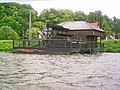
Floating deep water wheel - ship mill

In ship (s) mills, both spellings are common, this construction principle is also used. Here the ship is firmly moored in the river; the water wheel drives the mill on the ship. The ship mill has the advantage that it floats or sinks with the water level and therefore always has the same amount of water available.
Horizontal mills
Horizontal mills, also known locally as stick or floder mills, are characterized by a horizontal water wheel on a vertical shaft . The wheel drives the millstone without a gearbox. Only kinetic energy is used; the mill therefore needs a river with a steep gradient. Because of their simple and robust design and their suitability for small amounts of water, horizontal mills were widespread early on, especially in arid and mountainous regions of the Mediterranean region; But they can also be found in Northern Europe and in the Alpine region.
Special forms
Newly built water wheels are often special forms and are usually used to generate electricity.
- The Turas water wheel is an overshot, one-sided bearing water wheel. It is flanged on one side in a prefabricated frame construction, which is equipped with the gear unit and asynchronous generator unit , and is supported by the gear unit. With this design, the water wheel shaft is not required.
- The gravity water wheel is a medium-sized water wheel, in which the inlet and outlet losses have been minimized for maximum energy generation . The basis are the construction guidelines for Zuppinger waterwheels. The shape of the blades is not optimized for maximum output , but for maximum annual work (annual work in this case means the average amount of energy produced in one year). The gravity waterwheel is therefore more in line with today's needs for using the waterwheel to generate energy.
- The segment wreath waterwheel is a ventilated waterwheel with a modular design.
- The cross- flow turbine is essentially a further development of the water wheel.
- The lamellar turbine is based on the principle of an undershot water wheel.
- The water pressure machine is a further development of the medium-sized water wheel.
- The dynamic pressure machine is also a further development of the medium-sized water wheel.
- The hydropower screw is based on the principle of the Archimedean screw .
- The Steffturbine works on the principle of an overshot water wheel.
At Le Locle in the Swiss canton of Neuchâtel (NE) there are Europe's only underground mills, the cave mills of Le Locle . In the 16th century, water wheels were built into a waterfall in a multi-storey cave to drive a flour mill and threshing and sawmills .
Use to generate electricity

The water wheel has experienced a technical renaissance in the course of electricity generation based on renewable energies . Waterwheels are characterized by a cost-effective implementation in existing canals (e.g. irrigation canals), whereby the structural and technical size limitations of waterwheels (height of fall max. ≈8-10 m, flow rate max. ≈10 m³ / s) can be used in the area the small and very small hydropower, as shown in the diagram on the right.
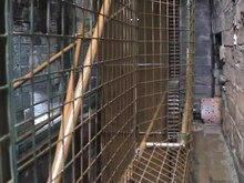
Water wheels in machine halls and wheel rooms
In the mining industry, water wheels and sweeping wheels were mostly installed underground in wheel rooms. But overshot or undershot water wheels were also installed in machine halls / wheel rooms for the promotion of water / drinking water or brine.


Combination with other forms of renewable energy
Existing waterwheel systems can be combined with other energy generators such as photovoltaics, small wind systems and combined heat and power units by using generators. A charge controller with an energy management system regulates and controls energy generation and distribution.
Even in earlier centuries, wind power and water power were used in combination in the form of combined "wind and water mills". Examples are the Hüvener Mühle , the Klostermühle Lahde and the Kilsdonker Mühle in Holland.
See also
literature
- Konrad Gruter : De aquarum conductibus; molendinis aliisque machinis et aedificiis. 3 parts, Venice 1424.
- Ferdinand Redtenbacher : Theory and construction of the water wheels. 2 volumes, Mannheim 1858.
- Carl von Bach: The water wheels. 1 vol. + Atlas, Stuttgart 1886.
- Wilhelm Müller: The iron water wheels. Volume 1: The cell wheels. Volume 2: The paddle wheels. Volume 3: Atlas. Veit & Comp publishing house, Leipzig 1899.
- Wilhelm Müller: The water wheels, calculation, construction and efficiency. abridged version of the previous volumes. Moritz Schäfer publishing house, Leipzig 1929.
- Heinrich Henne: The water wheels and turbines. 1 volume + atlas. Bernhard Friedrich Voigt publishing house, Leipzig 1903.
- F. Beyrich: Calculation and execution of the water wheels. JM Gebhardt's Verlag, Leipzig 1905.
- CGO Deckert: The hydraulic motors. (The School of the Machine Technician 14) Moritz Schäfer Verlag, Leipzig 1914.
- K. Albrecht: Water Wheels and Turbines Part 2 in Volume 5 Motors 1. from Uhland's handbook for the practical machine designer. Verlag W. & S. Loewenthal, Berlin approx. 1915.
- Water wheel . In: Meyers Konversations-Lexikon . 4th edition. Volume 16, Verlag des Bibliographisches Institut, Leipzig / Vienna 1885–1892, p. 427.
- KW Meerwarth: Experimental and theoretical investigations on the overshot waterwheel. Dissertation. TU Stuttgart, 1935.
- DM Nuernbergk: Water wheels with a crop channel - calculation bases and new findings. Moritz Schäfer Verlag, Detmold 2005, ISBN 3-87696-121-1 .
- DM Nuernbergk: water wheels with free slope - design and calculation bases. Moritz Schäfer Verlag, Detmold 2007, ISBN 978-3-87696-122-4 .
- Richard Brüdern: How to build water wheels - a contribution to the history of technology, calculation and construction of water wheels. Self-published, Hannover 2006, OCLC 255703382 .
- Axel Feuss: water, wind and industrial mills in Hamburg. (= Workbooks on the preservation of monuments in Hamburg, topic series Volume 9) Boyens Medien, Heide / Holstein 2007, ISBN 978-3-8042-1234-3 .
- Klaus Grewe: The relief representation of an ancient stone saw machine from Hierapolis in Phrygia and its significance for the history of technology. International conference 13. – 16. June 2007 in Istanbul. In: Martin Bachmann (ed.): Construction technology in ancient and pre-ancient Asia Minor. (Byzas, Vol. 9) Istanbul 2009, ISBN 978-975-8072-23-1 , pp. 429-454. (German, partly English)
- Julius Weisbach: Textbook of Engineering and Machine Mechanics, Second Part: Practical Mechanics, Verlag Friedrich Vieweg u. Sohn, Braunschweig 1846, Chapter Four "From the vertical waterwheels" pp. 154–243, Strauberad (Figs. 219 and 220) and Staberad pp. 201–202; Chapter five "From the horizontal waterwheels" (turbines) pp. 243–334 (geometric structure and calculation of many different waterwheels and turbines)
Web links
- Information on modeling waterwheels
- Theory and construction of the water wheels v. Ferdinand Jacob Redtenbacher
- A page with extensive search options on the subject of watermills
- Information page about the Möhrendorfer water pumping wheels
- Sweeping wheel Function of a sweeping wheel (promotion & driving skills)
- The Harzer Kehrrad ( Memento from July 10, 2004 in the Internet Archive )
- Pictures of the Clickmill from Dounby on Orkney
- The oldest watermill north of the Alps (from Welt-Online)
- 25,000 water mills rattle for clean electricity
- Water wheel of the Lower Fulling Mill, Rothenburg ob der Tauber
Individual evidence
- ^ Tullia Ritti, Klaus Grewe, Paul Kessener: A Relief of a Water-powered Stone Saw Mill on a Sarcophagus at Hierapolis and its Implications. In: Journal of Roman Archeology. Vol. 20 (2007), pp. 138-163 (161).
- ^ John Peter Oleson: Greek and Roman Mechanical Water-Lifting Devices: The History of a Technology . University of Toronto Press, 1984, ISBN 90-277-1693-5 , pp. 325ff.
- ^ John Peter Oleson: Water-Lifting. In: Örjan Wikander: Handbook of Ancient Water Technology, Technology and Change in History. (Technology and change in history 2). Brill, Leiden 2000, ISBN 90-04-11123-9 , pp. 217-302.
- ↑ Alfred Dumreicher: Entire overview of the water management of the north-western Upper Harz. Clausthal 1868. (Extended new edition: Volkmar Trunz (Ed.), Oberharzer Geschichts- und Museumsverein eV, Clausthal-Zellerfeld 2000, ISBN 3-9806619-2-X ).
- ↑ a b c d e f g h Jutta Böhm: Mühlen-Radwanderung. Routes: Kleinziegenfelder Tal and Bärental. Weismain environmental station of the Lichtenfels district, Weismain / Lichtenfels (Lichtenfels district), 2000, p. 6.
- ↑ Mining monuments in the mining region Erzgebirge / Krusnohory, German / Czech, Karlovy Vary district, Czech Republic 2014
- ↑ Julius Weisbach: Handbook of mining mechanics, second volume: Mathematische Maschinenlehre, Weidmann`sche Buchhandlung Leipzig, 1836, p. 108, efficiency of the overshot water wheel
- ↑ Julius Weisbach: Handbuch der Bergmaschinen-Mechanik, second volume: Mathematische Maschinenlehre, Weidmann`sche Buchhandlung Leipzig, 1836, S. 107-108: efficiency of the overshot water wheel; Efficiency of the medium-sized waterwheel p. 111
- ^ Julius Weisbach: Textbook of engineering and machine mechanics, Verlag Friedrich Vieweg u. Sohn, Braunschweig 1846, Chapter Four "From the vertical waterwheels" pp. 154–243, pp. 201–202: Strauberad (fig. 219 iron and 220 wooden screwdriver, p. 201) and Staberad (fig. 218, p. 199 )
- ↑ Julius Weisbach: Handbuch der Bergmaschinen-Mechanik, second volume: Mathematische Maschinenlehre, Weidmann`sche Buchhandlung Leipzig, 1836, S. 116–117: Chapter 32: Undershot water wheels: rod wheels, screw wheels and ship mill wheels
- ↑ Julius Weisbach: Handbuch der Bergmaschinen-Mechanik, Second Volume: Mathematische Maschinenlehre, Weidmann`sche Buchhandlung Leipzig, 1836, pp. 116–117: Chapter 37: Undershot water wheels with crooked blades (Poncelet water wheels)
- ↑ Julius Weisbach: Handbuch der Bergmaschinen-Mechanik, Second Volume: Mathematische Maschinenlehre, Weidmann`sche Buchhandlung Leipzig, 1836, pp. 116–117: Chapter 37: "Undershot water wheels with crooked blades (Poncelet water wheels)", (mentioning the efficiency undershot water wheels)
- ↑ a b c d e f proceedings of the 43rd IWASA 2013 Chair and Institute for Hydraulic Engineering and Water Management Rheinisch-Westfälische Technische Hochschule Aachen; Editor: Univ.-Professor Dr.-Ing. Holger Schüttrumpf (PDF; 1.06 MB).
- ↑ a b c Status report on the development of the dynamic pressure machine , Institute for Hydraulic Flow Machines at Graz University of Technology .