
Schönbrunn dam
| Schönbrunn dam | |||||||
|---|---|---|---|---|---|---|---|
 |
|||||||
|
|||||||
|
|||||||
| Coordinates | 50 ° 32 '36 " N , 10 ° 52' 51" E | ||||||
| Data on the structure | |||||||
| Construction time: | 1967-1979 | ||||||
| Height above valley floor: | 64.7 m | ||||||
| Height above foundation level : | 66.7 m | ||||||
| Height of the structure crown: | 545.12 m | ||||||
| Building volume: | 1 100 000 m³ | ||||||
| Crown length: | 260 m | ||||||
| Crown width: | 6.2 m | ||||||
| Slope slope on the air side : | 1: 1.6 | ||||||
| Slope slope on the water side : | 1: 2 | ||||||
| Data on the reservoir | |||||||
| Altitude (at congestion destination ) | 542.8 m | ||||||
| Water surface | 1 km² | ||||||
| Storage space | 23.28 million m³ | ||||||
| Total storage space : | 23.88 million m³ | ||||||
| Catchment area | 30.2 km² | ||||||
| Design flood : | 47 m³ / s | ||||||

The Schönbrunn dam is located in the southern Thuringian Forest in the municipality of Schleusegrund ( Hildburghausen district , Thuringia). It was put into operation in 1977. The dam is located about 20 kilometers south of Ilmenau and 15 kilometers northeast of Schleusingen . The river lock is dammed .
use
The dam is used to supply drinking water in the Suhl , Hildburghausen , Ilmenau , Meiningen and Schmalkalden regions as well as for flood protection . From the Schönbrunn dam, 230,000 consumers in southern Thuringia are supplied with around 27,000 m³ of drinking water every day. The dam belongs to the Thuringian long-distance water supply .
Hydrology
The catchment area of the dam covers an area of 30.2 km². It consists of 88% mixed forest , in the upper part pastures dominate. With altitudes around 800 m above sea level. NN, the ridge of the low mountain range represents the northern boundary of the catchment area as a natural watershed. The catchment area in the upper Schleusetal, which has a mean annual precipitation of 1060 mm, and the high runoff values caused by the Atlantic-oceanic climate (total mean runoff: 0, 71 m³ / s) offer favorable conditions for the construction of a drinking water dam. The mean annual runoff is 22.3 million m³. The dam is fed by the larger tributaries (Böse) Schleuse, Tanne, Gabel and Tränkbach as well as by a number of smaller streams. These include the Eselsbach, Kleiner Gabelbach, Haschbach, Schulbach, Märtersbach and Schwefelbach tributaries.
geology
The subsoil of the reservoir area consists of Algoncan slate (oldest rock in the Thuringian Forest). This belongs to the core zone of the Schwarzburger Saddle in the Katzhütte layers. In several places the slate is interspersed with igneous rock dikes (syenite porphyry, porphyrite), whereby the adjoining slate was metamorphically changed. Shale sedimentary rock was formed by tectonic stress on the Algonquian sediment . This was changed in such a way that it is in a jointed and cleaved state. There are no fissures in the area of the eruptive dikes . Slate, which had no influence on the contact, is gray / dark gray rock. Slate of fine grain with embedded greywacke is predominant . However, this rarely occurs. The clay slate rock is bordered at the base by sandstone, breccias, conglomerates and in the hanging wall by fine sandstone. Some of these layers of the Goldisthaler Group dip steeply and reach a thickness of up to 600 m.
dam
The dam of the dam is a rubble dam with an asphalt concrete outer seal. The total area of the outer seal is 22,000 m². The sealing body (total thickness 30 cm) is made of a bituminous base layer with a lower and upper sealing layer and a drainage element in between, as well as a surface seal that serves to protect the surface of the sealing body.
The supporting structure of the barrier structure consists of clay slate (0–400 mm) from the Goldisthaler Group, which was extracted in the immediate vicinity from a quarry in the reservoir . A filter with a bed of stones (200/400/700 mm) is installed at the dam foot on the air side. This construction element is of great importance for the stability of the dam. Its task is to collect the groundwater and seepage water under the dam and discharge it in a controlled manner. Furthermore, a favorable influence on the water flow in the dam body should be made possible. This is associated with a significant increase in stability compared to ground and slope failure. Several berms were created on the airside embankment . The air side received a topsoil order and was partially planted. The subsurface of the rock embankment dam is sealed by a two-row sealing curtain. In the floodplain, the injection curtain extends up to 40 m into the subsoil; A grouting depth of at least 25 m was planned on the slopes. The dam has a pre-lock .
Extraction systems

The water for drinking water treatment is drawn from a raw water withdrawal tower, which was constructed using the sliding construction technology with a total height of 76 m. The tower was designed as a so-called wet tower in a two-chamber system. This enables the tower to be emptied in whole or in part for repairs, even if the dam is blocked. At the same time, the supply of raw water via a chamber can be maintained through the partition wall. The extraction takes place via eight raw water inlets DN 800, which are arranged at different heights. The control of the removal height is realized via siphons using compressed air. The entire tower itself stands on a 12.40 m high base foundation. This was placed on a 1.95 m thick reinforced concrete slab.
In front of the base foundation is the inlet structure of the bottom outlet of the dam. Horizontal and vertical rakes are arranged on the intake structure. There is also the possibility of blocking the inlet by emergency guards. Two bottom outlet pipes DN 1200 are integrated in the tower base, which are reduced to DN 1000 in the valve chamber. The bottom outlet pipes and the raw water pipe DN 600 are led through the base foundation into the adjoining valve chamber, where they end through a downstream tunnel in the air-side valve house with stilling basin. Raw water and bottom outlet pipes are protected by casing pipes between the tower base and the valve chamber. The pipes are shut off on the water side by flaps in the valve chamber, the bottom outlets in the valve house are regulated by needle valves DN 800, which blow out into the stilling basin. If the dam is completely blocked, the bottom outlets can each discharge 6.2 m³ / s. The raw water is transported from the valve house to the water treatment system via two DN 800 pipes. The waterworks is located directly below the blocking point of the dam.
Access to the extraction tower is made possible via a 130 m long bridge. The superstructure of the bridge structure was designed as a hollow box profile. The bridge itself is supported by two 50 m and 25 m high reinforced concrete pillars. During the construction of the access bridge, the incremental launching method was first used in the GDR.
Flood relief system

The flood relief system consists of an inlet structure arranged on the right slope, a 40-meter-long fixed overflow with a collecting channel, a weft channel and a separate stilling basin , in order to discharge the water without damage in the event of a flood. As with all dams, the relief system is designed for a design flood, which statistically can occur every 1000 years (HQ 1000).
Pre-lock

In the planning phase of the Schönbrunn dam, two pre-dams were initially planned. However, only the pre-lock Schleusegrund was implemented. A pre-closure planned in the Tannengrund was not implemented. Due to a complex slope movement in the Pfaffkopf area, the originally intended location of the pre-dam had to be relocated in Schleusetal, as the location was in an area at risk of slipping. The dam structure in the sluice base primarily serves to improve the water quality of the dam inflow. This can be achieved through sediment retention (sedimentation of mineral and organic material) and nutrient elimination in the inflow. Without the pre-dam, the root of the reservoir of the main dam would dry out at very low water levels. As a rule, the pre-dam is operated in such a way that the water level in the reservoir is kept constant (a reservoir operated in overflow), even if the reservoir of the main dam experiences large fluctuations in the water level.
Technical specifications:
| Height above foundation level | 24.25 m |
| Height above valley floor | 20.50 m |
| Crown length | 165.00 m |
| Crown width | 4.70 m |
| Embankment, on the water side | 1: 2.5 |
| Embankment, airside | 1: 2.5 |
| Building volume | 75,000 m³ |
| Storage space | 0.74 million m³ |
Measuring and control devices
dam
An important control element in dam monitoring are the geodetic deformation measurements. In addition to hydrostatic and geometric leveling , trigonometric position measurements and geometric alignment are also used. Vertical and horizontal displacements are recorded on all fixed parts of the structure. Measurement points in the dam foundation, in the inspection passage, in the bottom drainage tunnel, on the dam crest, on the berms and on the service walkway and extraction tower are included . In the inspection passage of the main dam, the field joint movements are monitored with a micrometer . The inclination of the water intake tower can be checked with a floating plumb line. Furthermore, hydrometric measurements are carried out. Essentially, the bottom water pressure is recorded. These measurements serve to identify a possible upwelling of the dam. According to technical specifications, the pressure from the water side to the air side must decrease to a predefined level. The measurement of the seepage water from the dam foundation, the outer skin seal, the inspection duct joints and the measurement of ground and crevice water levels at the dam foot or in the embankment fillets expand the extensive measurement and control program. The seepage water from the outer skin seal is tapped via 70 seepage water measuring points, collected via a drainage channel and measured. Settlement measurements are carried out using a Freiberg hose bolt scale. It was found that the dam crest has set by 12 cm since 1975. These settlement phenomena are based on consolidation processes after the compaction of the embankment. Soil mechanical calculations made it possible to predict the expected settlement quite well during the construction phase of the dam. The movements of around 1 mm per year still measured today result from the weight of the structure itself (decay phase).
Slope movement
In 1967, in the course of geological investigations, several active hangar areas were found in the reservoir of the dam. For the safe operation of the dam, the fork slope is of the greatest importance. By far the most complicated slide is in the storage space here. The sliding slope itself has a total volume of 4.8 million m³ with an average thickness of 22 m to 25 m. The slope movement extends from the bottom of the lock to the altitude of the mountains and overcomes a height difference of 200 m.
The active movement hangar areas in the storage space, here especially the fork movement, are controlled by extensive monitoring measurements. Geodetic deformation measurements , extensometer measuring sections , inclinometers , geophysical, meteorological and hydrometric measuring methods are used here. The extensometer measurements can be seen as an early warning system of the monitoring concept of the slope movement.
In cooperation with the then Central Institute for Earth Physics of the Academy of Sciences of the GDR in Potsdam, a complex seismological report on the Frauenwald-Schönbrunn area was developed. In evaluating the results of the investigations, it is assumed that the seismicity for the area can be classified as low. A maximum intensity of 5 degrees ( MSK scale ) is specified for a one hundred year earthquake event . In the aftermath of the mining-induced seismic event of March 13, 1989 in VEB Werra potash plant in Merkers, the slope areas were subjected to an in-depth investigation in order to determine the effects of the rockfall. The seismic influence on the siting area of induced events in the Werra area is of subordinate importance for slope stability.
- Slope movement fork

overall view
... with the upstream Pfaffkopf accumulation area
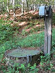
Manhole of an extensometer section


execution
The dam was planned by the Erfurt and Dresden Water Management Project (VEB PROWA). During the planning, essential requirements of the responsible water management department (WWD) Werra-Gera-Unstrut (later the water management department Saale-Werra) were taken into account as a perspective planning for the use and management of the dam. The structural implementation of the project was carried out by VEB Spezialbaukombinat Wasserbau, Operation Talsperrenbau Weimar, as the main contractor. A large number of other special construction companies from all over the GDR implemented important sub-projects on the construction site of the Schönbrunn dam. These included, for example, the Ostharz storage facility, Nordhausen shaft construction , BMK Erfurt, BMK Chemie Halle, motorway construction combine Weimar , civil engineering Berlin and power plant construction Dresden.
Relocation

Due to the construction of the dam, the districts of Unter- and Obergabel and the Tannenmühle of the community of Schönbrunn had to be relocated. Furthermore, the Tränkbachsmühle of the Frauenwald community and the LPG Neustadt were relocated from the storage space and the catchment area. A total of 22 families were resettled.
In October 1968, the last residents of Gabel left their homes. The cemetery was moved in 1969, and in the period from 1970 to 1974 the Schönbrunn district was almost completely demolished. Only a forester's house and a house with a barn remained in Obergabel. Today the buildings are used by the forest.
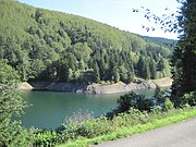
Touristic
There is a circular route around the dam, 15 km or 20 km long, on which you can hike and cycle. Fishing is allowed at the Schönbrunn dam with a fishing permit.
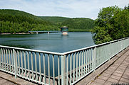
photos

The dam seen from the dam of the Schleusegrund reservoir
Schönbrunn dam with extraction tower


See also
literature
- Around the Schönbrunn dam (hiking booklet). Hermann Haack Verlag, Gotha 1992.
- Dams in Thuringia. Thuringian dam administration, 1993.
- Schönbrunn Dam (information sheet). Thuringian dam administration (dam master's office Schönbrunn).
- Operation and rehabilitation of dams, advanced studies (water and environment). Bauhaus University Weimar, 2009.
- Slope movement fork. Thuringian long-distance water supply, 2007.
Web links
Individual evidence
- ↑ W. Krüger, W. Streit: Execution of a water extraction tower and the pillars of the service walkway in sliding construction. Technical information from the VEB Bau- und Montagekombinat Chemie. Halle 1975, No. 11, pp. 10-16
- ↑ J. Schuchardt, H. Vockrodt, D. Feistel: First application of incremental launching in the GDR. In: Bauplanung - Bautechnik, Volume 30, Issue 7, July 1976, pp. 327-330
- ↑ H.-P. Otto, W. Witter: The monitoring of a sliding slope by a partially automated extensometer system. Leipzig / Schönbrunn 1993
- ^ Heidi Moczarski, Hans-Jürgen Salier : Small district chronicle Hildburghausen. Verlag Frankenschwelle, District Office Hildburghausen, 1997, p. 138