
Electron beam material processing
The generic term electron beam material processing generally summarizes manufacturing processes of material processing with the help of electron beams .
Basics
Beam processes for thermal material processing use either the electron beam or a laser beam . The former consists of highly accelerated particles, the latter of electromagnetic waves, which results in significant differences - both in beam generation and manipulation and, in particular, in the interaction with the material of the machined components. Both blasting processes cannot be compared with the various arc processes. Like laser welding, electron beam welding takes place in a vacuum under reduced pressure. The following describes the various options for material processing with the electron beam.
Historical
The possibility of processing material with what was then known as the cathode ray was discovered as early as 1879 ( Johann Wilhelm Hittorf and William Crookes ), and in 1949 the era of conscious thermal material processing with the electron beam began ( Karl-Heinz Steigerwalds ). In 1952, Steigerwald built the first electron beam drilling machine and in 1958 the first electron beam welding machine. In the course of the following decades some companies entered the scene ( Zeiss first), and today various high-tech companies in different countries of the world (especially Germany , Great Britain , France , USA and Japan ) manufacture EB machines.
The spectrum and scope of electron beam material processing (welding, drilling , surface modification ) has developed continuously since the beginning, see Sect. o. Research and technical development not only lead to increasingly "sophisticated" devices and processes, but also to completely new applications.
Beam generation
In electron beam technology, the required energy is brought into the process zone by electrons accelerated by high voltage (mostly 60–150 kV). The jet is formed under a high vacuum (<10 −4 hPa) using a triode system consisting of a cathode , control electrode ( Wehnelt cylinder ) and anode .

The directly or indirectly heated cathode (at high negative potential) emits free electrons, which are then accelerated to earth potential to the anode, which is only a few centimeters away. In doing so, they reach speeds that amount to several hundred thousand km / s. These electrons “race” through the anode bore towards the workpiece, where their kinetic energy is converted into heat with almost no loss. These active energy is determined by the product of the high-voltage U B and beam current I B . The size of the desired beam current (usually well below 1 A) is set by the negative control voltage U S , which provides a certain (field) resistance to the electrons emerging from the cathode. This power control works extremely quickly. On the way between the cathode and the workpiece, the beam is formed by the electric field of the control electrode as well as by magnetic fields from coil systems: The stigmator eliminates any astigmatism that may occur in the beam, the adjustment coils ensure that the beam passes through the focusing coil , which in turn is exactly centric Position of the focal point (minimum spot size: a few tenths of a millimeter, highest power density: up to 10 7 W / cm 2 ) relative to the workpiece.

Electron beam focusing

Setting different focus positions


Of particular importance for the application of the electron beam is the possibility of being able to deflect it extremely quickly (almost without inertia) by means of (crossed) magnetic fields. This means that not only can the beam be positioned exactly on the joint, but each point on a surface can be exposed to a defined beam energy and thus a complex effect (multi-bath technology, multi-process technology, surface modifications) can be achieved.

The advantage of this fast beam deflection (point-to-point up to 1 MHz) is the fact that the material melted by the beam needs significantly more time to solidify than the beam to "return" and continue the energy input. In addition, thanks to this deflection, it is possible to scan the real workpiece surface with the beam itself and to generate an image of it using the backscattered electrons - especially including the joint (and the processor location). In other words, the electron beam itself can be used as a joint sensor. And, of course, the beam deflection is used to "stir" with the focused electron beam in the local weld pool (circular, elliptical, linear, etc. - comparatively slow, less than 1000 Hz, and with low amplitude) so that conditions that are advantageous in terms of welding metallurgy are achieved.
All the components mentioned for beam generation and shaping are contained in the so-called electron beam generator, which is connected to the working chamber by a vacuum valve. The generator can be arranged at almost any angle.
Electron beam welding
The electron beam welding (EN ISO 4063: Process 51; English electron beam welding , EBW) has to use than fusion welding process for metals because of its special characteristics outstanding properties that his commitment to both micro-devices as well as thick-walled large parts, both in the individual production and enable in mass production . Its production-related advantages can always be used technically and economically if the possibilities of electron beam welding are consistently taken into account in the design of a component. The characteristics are summarized in key words below.
Process characteristics
- Minimal heat input into the welded part (compared to other processes with a given seam)
- almost complete absorption of the beam energy (kinetic particle energy) in the metal
- Seam cross-section (seam profile) adjustable by beam parameters - especially also with parallel flanks
- minimal distortion of the component
- Due to the deep welding effect, large material cross-sections can be welded in one layer
- Welding is also possible in hidden places (through cover sheet or similar)
- almost all metals and many metal combinations can be welded (suitability for welding depends on metallurgical limits)
- Autogenous process in the sense that the base materials of the joining partners are fused together in a narrow area
- Use of filler metal possible (to bridge gaps and / or for metallurgical reasons)
- high welding speeds (and high cooling rates)
- best protection of the melt in a vacuum
- precise and reproducible parameter setting as well as immediate parameter documentation
- practically inertia-free beam influence (position, focusing, power distribution) through very quickly changeable magnetic fields
- Long-term stability of beam generation and shaping
- automatic beam-impact positioning as well as electronic beam adjustment and process monitoring possible
- fully automatic process flow
scope of application
- Preferably joining of finished individual parts (ideally with zero gap )
- suitable for individual part production or for mass production (with different machine types)
- EB machine always delivered as a complete unit; Linking option in production line / cell
- Lowest consumption costs (over 40% energy efficiency of the entire machine , no protective gas , no wearing components of the beam optics, long cathode service life )
- Vacuum chamber and evacuation time adaptable to the respective application
- Special form of EB welding also in a free atmosphere (NonVac)
- Absolutely safe radiation protection (X-ray) in all cases: through working chamber (vacuum) or housing (NonVac)
- in industrial application since the middle of the 20th century - worldwide and in all branches
- Greatest economic effects when considering the possibilities of EB welding (shape, materials, production stages) already in the component design phase
- rarely recommended: 1: 1 replacement of conventional joining processes with EB welding
It is an advantage and not a disadvantage of the method that the individual parts to be joined can (and should) be precisely prepared because it allows the highly effective production of more or less complex components.
Deep welding process
The welding process usually takes place in a vacuum (with so-called NV-EBW, non-vacuum electron beam welding , electron beam welding at atmospheric pressure , this can also be done under normal pressure , see below). When the electrons hit the workpiece, they convert almost their entire kinetic energy into heat through collision processes with the metal ions. Depending on the energy, power density and welding speed as well as the material properties, the beam penetrates to a certain depth, forming the so-called deep welding capillary (vapor channel, keyhole), which is filled with metal vapor plasma and surrounded by molten metal. The latter solidifies as the beam impact point progresses and thus forms the weld metal - the connection. In this way, cross-sections from a few tenths of a millimeter to a few hundred millimeters can be welded in a single layer - of course depending on the specific parameters and machines. Moreover, no additional material is required (although such a material can also be added for various reasons).

Process principle: process in a few milliseconds

Arc seams and EB seams in comparison, here 30 mm

Arc seams and EB seams in comparison, here 100 mm


Incidentally, the electron beam does not need a gap to penetrate deeply, blind seams show the seam profile just as precisely in the cross-section. This is preferably provided with parallel flanks (depending on the parameters) so that possible shrinkage does not lead to undesired workpiece distortion.

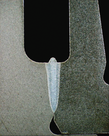
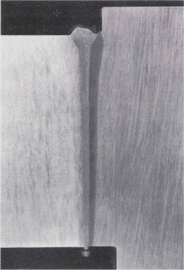
Cross section, seam depth 13.5 mm

Cross section, seam depth 170 mm (welded with horizontal beam)

Principle of material combinations using electron beam welding


The electron beam can also be used to weld material combinations - a crucial option in the structural design of components. This not only applies to the combination of different steels, but also - within the limits of metallurgy and load requirements - the connection of very different metals.
Quenched and tempered steels
Black and white connection

Steel and bronze


The possibility of single-layer welding without filler material at comparatively high welding speeds creates the basis for a high level of economic efficiency of the process, which is further increased by the “exhaustion” of the above-mentioned constructive solutions for cost-effective production of complex components.
Electron beam welding machines
As described above, the electron beam is generated and shaped in a high vacuum. The welding process usually also takes place in a vacuum - from a fine vacuum of a few 10 −2 hPa for steels and to a high vacuum of 10 −6 hPa for reactive ( refractory ) materials such as niobium , titanium and the like. a. Depending on the application, the machines are designed very differently, but they always include the main assemblies shown here, which are basically completely manufactured in one unit and delivered ready for operation. Such a machine not only includes all functional units, but thanks to the vacuum working chamber also provides reliable protection against the X-ray interference associated with every electron beam process .

The working chamber sizes are specific to the respective application and currently range from a few liters to 630 or even 1000 m 3 . Powerful units tailored to the respective machine type and application are used to generate the vacuum. Nowadays (2015) this leads to very short evacuation times (sometimes a few seconds), the effect of which on the non-productive times is further reduced by clock and / or lock technology in the machine structure.
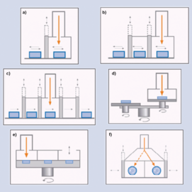
Basic types of electron beam machines

Large chamber machine

Lock cycle machine


The investment costs for a fully functional electron beam machine naturally depend on the particular application. There is no electron beam machine according to the catalog, although certain basic designs can be adapted. Universal machines allow the processing of a wide variety of components, whereas special machines are optimized for a single purpose (also for component families).
As far as the operating costs of an electron beam machine are concerned, these include low consumption costs for cathodes, vacuum pump oils and seals, but not costs for additional materials - especially for protective gases, these are not required. The main cost block is electrical energy from the grid. And it has been proven that the conversion of the network power - measured for all units of the machine together - takes place to significantly more than 40% in beam power on the workpiece (with very high beam powers also over 70%). It should be emphasized that the magnetic and electrical fields for generating, shaping and deflecting the electron beam can practically not be contaminated during operation and also do not have to be cooled.
In principle, every electron beam machine works fully automatically - according to a numerical program created and approved during the respective process qualification . The operator is primarily responsible for loading and unloading, and to a certain extent also for monitoring trouble-free operation.
In addition, it is not only possible, but also daily practice, especially in mass production, to automatically link the electron beam machine with upstream and downstream processing stations within a production line or cell. The device technology is of particular importance , which - as with other welding processes - is necessary to securely fix the components to be joined and to move them in the automatically running process. It is application-specific in each case. Incidentally, it is also possible to carry out the welding movement - with the workpiece at a standstill - using the programmed magnetic beam deflection.
Application range
Electron beam welding is used for highly stressed and cost-intensive constructions in the aerospace industry as well as in energy and nuclear technology, but also to a large extent in the mass production of demanding parts in automotive and mechanical engineering . This applies to all areas of the world - wherever the technology has reached a high level of development. Electrical and energy technology, sensor technology , medical technology , components of the food industry , scientific equipment and much more - EB technology is in use everywhere.
It is of the utmost importance that the possibilities of EB material processing (especially EB welding) are used in the design phase of a component or assembly in such a way that, on the one hand, inexpensive manufacturing technologies (e.g. for the individual parts) are used. can use and on the other hand achieves optimal utility properties.
While large companies often operate one or more (up to 70 e.g., because the economic and technical effects are so outstanding) purpose-specific electron beam machines , other users use the service of subcontractors ( job shops ), who use universal machines for a wide range of tasks and customers operation - down to batch size 1. There, "beginners" can also have their first samples welded, work out procedural verifications and start series production without having to buy their own EB machine.
Such companies also get support from expert consultants - both with regard to the constructive possibilities (design, materials, etc.) and the technology development as well as with regard to the optimal machine technology or contract partners.
Thanks to the extremely low level of wear and tear on EB machines, they have a very long service life - 40 years are not uncommon. This is of course an advantage for operational cost accounting (depreciation). And in many cases "old" EB machines can also be adapted to new applications.
Electron beam welding in the atmosphere (Nonvac-EBW)
The use of the electron beam for welding in a vacuum is dominant. With so-called nonvac electron beam welding, however, the beam generated in a high vacuum - as always - is "threaded out" to the open atmosphere via pressure levels so that a - often very large - workpiece to be processed does not have to be placed in a vacuum chamber.

Electron beam in vacuum
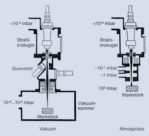
Variants of electron beam welding

Electron beam in atmosphere


While the electron beam in the vacuum, depending on its quality, is little or not scattered by residual gas molecules, so that working distances of a few decimeters up to 2 m are possible (see mean free path ), the electrons emerging from the nozzle collide with the Nonvac process (accelerated with 150 kV or 175 kV) with the particles of the dense atmosphere, whereby they are strongly scattered. Depending on the route (the photo above on the right covers approx. 400 mm and does not show the electrons themselves, but the gas molecules they stimulate to glow), the power density in the beam is reduced, but it is between 5 mm and 30 mm at working distances still high enough to create a deep weld effect. The possible beam powers are up to 30 kW.

Nonvac jet power density as a function of distance

Seam shapes in the NV-EBW

Flanged seam on AlMg3 - 2 × 2.5 mm


An essential effect of the slightly widened beam is the possibility of bridging noticeable component and process tolerances (position, distance, edge offset, joint gap, etc.), which is particularly advantageous for large components.
A torch made of metal vapor plasma forms above the welding point, which protects the liquid weld metal - this plasma is penetrated by the electron beam practically unhindered (without absorption). No shielding gas is required for nonvac electron beam welding either.
The enormously high speeds that are possible with the Nonvac EBW should be emphasized. The flanged seam shown in the picture is welded at 14 m / min, and 1 mm thin aluminum sheets were tested with e.g. B. reached 60 m / min, with additional wire was also used to form the seam.
Due to the small jet outlet nozzle (approx. Ø 2 mm), it is not possible with the Nonvac-EBW to change the focus position - it is always set to this narrow point. A change in power density (with a given beam power) is possible via the working distance. And beam deflection cannot be used either. However, thanks to the beam broadening (compared to the beam in a vacuum), this does not represent a technological handicap, because the Nonvac-EBW does not weld the finest seams, but rather bridges tolerances. Only three process-relevant parameters have to be set: beam power, working distance and speed. This also results in the excellent robustness of the process.
Although the Nonvac-EBW does not require a vacuum working chamber, a radiation-safe housing (here against X-ray interference ) is required - as with laser beam welding - which is specially designed for the application.
Electron beam melting
Electron beam melting is a 3D printing process in which three-dimensional metal components are built up in layers. The starting material is metal powder, which is melted using an electron beam in order to subsequently solidify into a solid layer of material. The current layer is merged with the layers below, so that a solid component is created throughout.
Electron beam surface modification
On certain components, local, i.e. H. locally limited, a certain quality (property) of the surface is required, be it a certain hardness or an adapted wear resistance or a defined structure (texture). In contrast to other processes, the very precisely controllable electron beam offers the possibility of carrying out the desired surface modification (sometimes also: surface layer treatment) exactly where - and only where - it is functionally necessary. A distinction must be made between processes with melting of the surface (liquid phase processes) and those without (solid phase processes). The former allow the alloying or embedding of additional materials in the surface as well as the structuring, while the latter mainly for hardening and the like. Ä. Be used. Electron beam hardening is currently the most widely used.
The electron beam, which can be guided in a programmed manner, can strike the surface in lines, points or areas, so that the desired effect is achieved.

Variants of the electron beam surface modification

Examples of energy input grids

Heat input and drainage

.png)
.png)
Both linear or curved paths can be modified, but also cylindrical or conical surfaces as well as areas with irregular borders - the control (location and power) of the electron beam is virtually unlimited. Moreover, no workpiece-specific devices such as inductors or the like are required. What all these processes have in common is that the electron beam transfers the required energy into the surface, but cooling (quenching) takes place exclusively through the rapid heat dissipation into the solid component - external cooling is therefore not required. And the component as a whole is only thermally loaded to the extent that it is necessary for the local change in properties.
The transformation depths possible with the jet processes range from a few tenths of a millimeter (in the solid phase) to a few millimeters (in the liquid phase). In the most frequently used solid-phase hardening process for steels, the structure is austenitized to a certain depth (usually a maximum of 1 mm) through heat conduction due to the beam energy input , in order to immediately form martensite as a result of the self- quenching . All of this happens in a matter of seconds or a fraction of it.

Embedding of hard materials (micrograph)

Hardening of steel 51CrV (micrograph)


With modern machines for electron beam welding (equipped with the possibility of so-called fast beam deflection) one is generally also able to carry out surface modifications. In industrial applications, however - especially for mass-produced parts - special machines with a correspondingly high productivity are used.
Electron beam drilling
The short-term energy input with the electron beam leads to the formation of a vapor capillary which can penetrate the entire thickness of the workpiece. However, this channel closes again immediately after the jet is switched off - unless the molten metal is blown out quickly. This is exactly the basis of electron beam drilling, for which the back of the wall to be drilled is covered with an explosively vaporizing material. Blind holes are therefore not possible.

Principle of electron beam drilling

Thicknesses from 0.1 to 8.0 mm

Examples


Naturally, the resulting "holes" are not exactly cylindrical as with mechanical drilling, but for use in spinning plates for the manufacture of glass fiber or combustion chamber parts of engines and the like. Ä. This is also not necessary. Thanks to the direction-independent energy conversion of the electron beam in the metal, it is even possible to produce inclined bores. Depending on the sheet thickness , this technology can be used to drill holes extremely quickly: at 0.1 mm up to 5,000 holes per second and at 8 mm still 5 holes per second. For this purpose, beam guidance and component movement are synchronized "on the fly" with one another.
Electron beam cutting
Similar to “punctiform” electron beam drilling, the molten material generated by the electron beam has to be driven out of the cutting kerf during continuous cutting. This is of course not possible in a vacuum, but it is possible with the Nonvac application by directing a gas jet onto the cutting zone. This means that practically all metals in noticeable sheet thicknesses and, above all, at high speeds can be cut. The top and bottom edges of the cutting joints are almost free of burrs , the roughness of the cuts is small, and there are no irregularities either during piercing or at the end of the cut.
The samples shown in the picture are made of different metals: shipbuilding steel (15 mm or 4 mm thick), Cr-Ni steel (2 mm), aluminum (1 mm), copper (6 mm); the cutting speeds were 1.5 m / min to 17 m / min (depending on the sample). This shows the variety of possible uses - but not the limits. Blanks cut in this way are suitable for nonvac EB welding in the butt joint without further processing , so that large sheet metal plans can be produced with one and the same system, e.g. B. for shipbuilding .

Nonvac electron beam cutting technology

Sample sheets, cut with the Nonvac electron beam


literature
- Helmut Schultz: Electron beam welding (= specialist book series welding technology. Vol. 93). 3rd, completely revised and expanded edition. Verlag DVS - Welding and Related Processes, Düsseldorf 2017, ISBN 978-3-945023-85-3 .
- Klaus-Rainer Schulze: electron beam technologies (= knowledge compact. Vol. 1). DVS Media, Düsseldorf, 2011, ISBN 978-3-87155-225-0 .
- Patent DE102011115913A1 : Joining and separating workpieces with an electron beam in a non-vacuum.