DC machine

A DC machine , also DC motor , commutator motor or commutator machine, is a rotating electrical machine that is operated with direct current or generates direct current. Depending on the direction of the power flow, a distinction is made between the direct current motor (an electric motor to which electrical energy is supplied and mechanical energy removed) and the direct current generator (an electrical generator from which mechanical energy is supplied and electrical energy is withdrawn). DC machines can start under load and their speed can easily be changed.
The characteristic of classic DC machines is a mechanical inverter known as a commutator or pole inverter . With its help, a speed-dependent alternating current is generated in the rotor during motor operation . In generator mode, it converts the alternating voltage supplied by the rotor into a pulsating direct voltage.
There are also applications in which the same DC machine is used at times as a motor and at times as a generator.
A special form is the unipolar machine , with which direct current can be generated without using a commutator.
history

Aided by the development of the first galvanic elements in the first half of the 19th century, the first electromechanical energy converters were direct current machines. The original form of an electric motor was designed by Ányos Jedlik in 1829 . In 1832, the French Hippolyte Pixii built the first direct current generator. Antonio Pacinotti built a DC motor with a multi-part commutator around 1860. Friedrich von Hefner-Alteneck developed the drum armature in 1872 , which, with the work of Werner von Siemens on the dynamo-electric principle, opened up the possibility of self-excitation and industrial use in the field of large machine construction.
In the following decades, the direct current machine lost its importance in large machine construction due to the development of three-phase alternating current . In particular, the synchronous machines and, for low-maintenance drive systems, the asynchronous motor replaced the DC machine in many areas of application. The direct current machine with external excitation can be regulated well because the currents through the armature and stator windings can be controlled separately. The DC machine has therefore retained a certain importance, particularly in the field of highly dynamic drive systems, for example for driving machine tools with precise speed and torque control. In the low-power range, for example in model railways , the permanent magnet direct current motor is particularly common because of its simple design.
construction
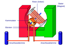
The machine has an immovable part, the stator . It consists of a yoke in the form of a hollow cylinder. The main poles and, in the case of larger machines, also the reversing poles are attached to it . The stator is not laminated , but consists of solid material, since there is no alternating magnetic field and therefore no eddy currents occur. The main pole core either carries the main pole or excitation winding , or permanent magnets generate the necessary main pole flux ( permanently excited machine). In the case of larger machines, the compensation winding is located in the pole pieces .
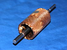
The rotatably mounted part of the DC machine is called the rotor or, in conventional machines, the armature . The rotor is laminated, as otherwise major eddy current losses would occur due to the reversal of magnetization. Most DC machines are designed as internal rotors: the rotor is the inner part, the stator the outer. In the case of external runners , it is the other way round.

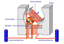
One or more coils on the armature are placed in a magnetic field of the stator in such a way that the Lorentz force and partly also the reluctance force generate a torque. The armature windings are connected via a commutator (pole inverter). The sliding contacts on the commutator (“brushing” metal brushes or carbon) change the polarity of the armature windings during rotation so that current in the corresponding direction always flows through those windings that move across the excitation field. A pulsating DC voltage can be tapped at the brushes. Several spatially offset winding loops (windings) smooth the voltage curve.
The brushes are made of a material that offers good , low- wear contact (often self-lubricating graphite, sometimes mixed with copper powder (see carbon brush ); for small motors, e.g. for cassette tape recorders, also precious metal brushes).
By reversing the principle (the armature is moved from the outside) you get a generator . Almost only permanent or externally excited construction methods are used to generate electricity. The commutator converts the generated alternating current into direct current.
The general motor behavior is determined by the field strength of the field winding and the properties of the armature winding (number of turns, number of poles).
Permanently excited DC machine
The stator magnetic field is often generated by permanent magnets in smaller motors (toys, actuators, blowers and radiator fans in motor vehicles, electric drives on bicycles ) . These magnets have become more and more powerful with the development of DC motors and would also allow larger motors to be built. However, the cost of large permanent magnets would be higher than that of the field winding.
Permanently excited motors, like separately excited machines, have very high inrush currents. Their operating behavior is explained in the section physical model. Permanently excited machines have the advantage that no energy is required to generate the magnetic field. This improves the efficiency, especially with a low total output. The disadvantage is that the field is not weakened and therefore the speed can be varied less.
Electrically excited DC machine
If the stator field is generated by an electromagnet, one speaks of electrical excitation. If the excitation winding is independent of the armature circuit, one speaks of external excitation. If the rotor and stator windings are connected to each other, one differentiates:
Inline machine

The series winding machine is also called the main winding machine; the field winding and armature winding are connected in series. The excitation winding must be low-resistance. When supplied with alternating voltage, both the excitation field and the armature current change direction after each half-wave, so that the resulting torque continues to act in the same direction even if the direction of the current is reversed. Therefore, a series motor can also be operated with alternating current. In this case, the iron core of the stator must be a laminated core in order to avoid eddy currents.
With single-phase AC power motors ( single-phase series motors ) are in older electric locomotives (hence the frequency 16.7 Hz compromise in traction network ) as well as tram - railcars to find. They are also found under the term universal motor or all-current motor in many household machines ( vacuum cleaners , kitchen machines ) and hand-held electrical devices ( drills ). The starters of large internal combustion engines (for example in trucks ) are series motors.
A series motor as a generator to (z. B. during electronic braking trams) run, his needs field winding be reversed, otherwise the generated, flowing through the field winding stream lifts the excitation field on.
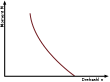
The torque of a series machine is strongly dependent on the speed ( series connection behavior ). At low speed, the mutual induction voltage of the armature winding is low. Therefore, a large current flows through the armature and the field winding, and a large torque can be applied. The mutual induction voltage increases with the speed. Current and excitation decrease and with it the torque of the machine.
Series motors, especially when operated with alternating voltage (" universal motor ", e.g. in vacuum cleaners), nevertheless have a significantly lower inrush current than shunt or permanent magnet motors. However, they provide a very high starting torque for a short time, which is why they are used in starters, tram vehicles and electric locomotives, where they can be extremely overloaded in short-term operation.
When operating with alternating current, the torque is pulsating at twice the mains frequency, so that compensating elements must be interposed in the case of large motors. This also applies to single-phase synchronous machines .
The connections of the armature are designated A1 and A2, those of the field winding D1 and D2. In the circuit shown, the motor rotates clockwise, recognizable by the arrow drawn in the armature.
Shunt machine
In the shunt machine, the exciter and armature windings are connected in parallel. The excitation current is only limited by the ohmic resistance of the excitation winding, which has a high number of turns and inductance . AC voltage operation is not possible because the excitation would lag far behind the armature current . The speed of large shunt machines is almost independent of the torque, which is why it is particularly suitable for applications in which the load torque fluctuates, but the speed should be as constant as possible, e.g. B. on conveyor belts and hoists where asynchronous motors are used.
Shunt motors can in case of interruption of the excitation circuit to go through , since the speed and power consumption increase drastically without agitation.
Shunt motors can work as generators (e.g. for braking) if an auxiliary voltage source or residual magnetization ensures that excitation is present when the braking process starts. With increasing excitation or speed, the generated voltage also increases - it is the voltage that counteracts the feeding current even when the motor is running and ensures a constant speed. It is therefore also called back EMF . The increase in the back EMF with the excitation, i.e. with shunt motors with the supply voltage, means that their speed depends little on the voltage as long as no magnetic saturation occurs. As the voltage decreases, the speed stiffness also decreases . In the case of an externally excited DC motor with an independently supplied, constant excitation field, on the other hand, the idling speed is proportional to the armature voltage.
The armature connections are designated A1 and A2, those of the field winding E1 and E2. In the wiring shown, the motor rotates to the right (clockwise), recognizable by the arrow drawn in the armature.
The maximum achievable torque is limited by the permissible armature current, which is mainly dependent on the cooling measures taken. Large bypass machines in rolling mills are externally ventilated in order to enable a high armature current and thus a high torque even at low speeds.
If the nominal operating voltage is suddenly applied to a shunt machine, a very high inrush current flows through the armature, which can trigger protective circuits. Large machines must therefore be started with a lower voltage. As a result, the characteristic curve is shifted parallel to low speeds so that it intersects the torque axis in an area outside the overload. The starting torque and the armature current at standstill are then limited. Along with the subsequent increase in the drive speed, the voltage can also be increased. Alternatively, series resistors can be used in the armature circuit to start up; this makes the characteristic curve flatter so that it in turn intersects the axis in an area outside the overload. The disadvantage of this method is the power loss at the resistor, which then has to be actively cooled if necessary.
Compound machine
The double-wound motor (also composite or compound engine called) combines the properties of the secondary and of the series-wound motor in a machine. It has a series winding and a shunt winding. Depending on the design, the double wound motor has different operating behavior. When compounded correctly , it has a slightly lower tightening torque than an equivalent series motor. Its speed then drops a little more under load than that of a corresponding shunt motor . It does not go through when idling. If the double-wound motor is over-compounded, it has predominantly series connection behavior, i.e. a high starting torque, but an unstable speed. When under compounding, it has predominantly shunt behavior , i.e. high speed stability, but lower tightening torque. The double-ended motor is because of its same speed-torque behavior to drive z. B. used by pressing and punching .
Separately excited machine
Here, the armature and excitation windings are fed from two different and separately adjustable DC converters . While the excitation voltage is the same as the armature voltage in the shunt machine, with separately excited machines you can increase the speed n beyond the nominal speed n N by reducing the excitation current, which is also referred to as a field weakening of the magnetic flux Φ . In the right diagram, this corresponds to the area with n / n N greater than 1. At the same time, the torque M is reduced . On the other hand, the armature voltage U A can be reduced independently of the excitation current in the separately excited machine . This leads to a power reduction and a simultaneous speed reduction at constant torque.
Because the armature and exciter windings can be regulated and controlled separately, different operating points below the red dashed torque characteristic can be achieved through the type of control. There are advantages such as high torque at standstill or at low speeds. For this reason, separately excited DC machines in particular played an important role in the field of highly dynamic drive systems, for example in machine tools or electric urban rapid transit trains such as the DB class 420 into the 1980s. In the following years, DC machines were increasingly replaced in these application areas by three-phase machines with upstream electronic frequency converters , which in combination offer the same advantages for highly dynamic drives with less maintenance.
Separately excited DC machines were previously also used in the Leonardsatz , which used to be the only variable-speed drive for high outputs, which consisted of a three-phase asynchronous motor , a separately excited DC generator and a DC motor.
Special designs
Bell anchor machines

Small machines up to around 100 watts with permanent magnets can also be built with a hollow rotor. The rotor is ironless, self-supporting wound and impregnated with synthetic resin.
In this case, the stator, a permanent magnet, lies within the rotor. The external motor housing made of iron forms the necessary conclusion for the magnetic flux of the stator. The electrical structure corresponds to the first illustration.
Due to the ironless structure of the rotor, the motor does not generate any cogging torque, it can be turned completely freely.
Since, in contrast to all other motors, no iron parts have to be remagnetized during operation, this motor is free from iron losses and achieves higher degrees of efficiency at high speeds. In particular, however, its rotational moment of inertia is lower, which is why highly dynamic, lightweight drives can be implemented with it. Model railway vehicles equipped with a bell armature motor are characterized by jerk-free running and good low-speed properties.
The large air gap in the excitation circuit, which results in a reduced magnetic flux density, is a disadvantage. The self-supporting construction makes high technological demands, since the centrifugal forces have to be absorbed and a subsequent balancing of the armature by material removal is not possible. The necessary shock resistance limits the anchor size.
The pancake motor is constructed in a similar way, but the rotor winding is not designed in the form of a cylinder but as a disc.
Brushless DC machine
The disadvantage of DC machines are the sparks that are generated by the brushes (“ brush fire ”). The brush fire is the main cause of high-frequency interference, which the motor feeds back into the line network during operation and which disturb other electrical consumers. It also limits the maximum speed of rotation as the brushes get hot at high speeds and wear out particularly quickly. Furthermore, high speeds also cause higher induction voltages, which can lead to a rotating brush fire.
With the development of electronics, smaller permanent magnet synchronous motors can be operated in such a way that they can be described from the outside in a similar way to a DC machine. These motors with electronic converters were advertised as brushless direct current (BLDC), which translates into brushless direct current machines in German. The machine is also known as an EC motor (EC for electronically commutated ). In terms of structure, these motors are identical to undamped permanent-magnet synchronous machines and can also be controlled as synchronous machines in applications that have sufficient self-damping.
Special effects
Anchor reaction
Since the armature has a current flowing through it, a magnetic field is also formed around it . This strengthens the main field on one side of the conductor and weakens it on the other. Overall, this means that the neutral range , in which the polarity of the current has to be switched, is somewhat delayed, i.e. H. shifts in the direction of rotation in generator mode and against the direction of rotation in motor mode. However, since the commutator does not adapt (i.e. it always switches perpendicular to the pole pieces and not perpendicular to the "effective" field lines ), an induction voltage is still present on the carbon brushes at the time of switching ( commutation ) , and sparks are generated Brush fire. In systems that require an even torque and are only operated in one direction of rotation (e.g. strong fans), the brush fire can be reduced by mounting the brush holder slightly twisted and then switching perpendicular to the effective field lines when in operation. However, this requires adjustment during operation and is rarely carried out today for reasons of cost. Instead, reversing pole windings and compensation windings are used in large machines , which "bend" the field lines back into the ideal position.
Counter tension
The armature rotates in the motor within the stator field. According to the generator principle, a voltage is induced in its coils even when the motor is running. This induced voltage is polarized like the operating voltage and therefore counteracts the rotor current. It is called counter voltage or back EMF. It is an important parameter of engines, with its help the idling speed of permanent magnet engines can be determined.
The armature current leads to an ohmic voltage drop at the armature resistor (copper), this voltage drop thus increases with the load on the motor (increasing current consumption) and causes the speed of motors to drop. In the case of large separately excited motors, this decrease in speed is very small.
The back EMF is strictly linearly dependent on the speed of the armature and the strength of the excitation. The back EMF can be used by control circuits to precisely stabilize the speed of permanent magnet motors; this is z. B. used in cassette tape recorders.
When the current direction is reversed (terminal voltage <EMF), the back-EMF turns the motor into a generator; it can be used for braking and energy recovery (regenerative braking).
There is no counter voltage when the motor is at a standstill. This is why externally and permanently excited DC motors have a high inrush current - the resistance of the rotor coils is comparatively small and therefore the current is very high when they are switched on.
Without limiting the start-up current, large motors or the supply network may be overloaded, so starting resistors are used in series with the armature , which are short-circuited in stages after start-up.
In the past, series motors in trams were also started up using a drive switch (step resistance); today this is achieved with less loss using a switching regulator ( chopper operation ).
In the case of electric locomotives, transformers with step switches were used, on which smaller variable transformers “hung” from step to step. Here, too, power electronics ( IGBT switches)
are used instead today
Physical model
If the consumer counting arrow system is specified (as assumed e.g. in Ohm's law ), the following applies
If the current is assumed to be constant over time , it follows
If the law of induction is also taken into account , it becomes
This equation can be interpreted as follows:
For constant and in practice small , the induced voltage is insignificantly smaller than . With a constant flux n is therefore approximately proportional to the armature voltage. In this way, the speed can be controlled via the armature voltage. One speaks of the anchor adjustment range. For the case and one speaks of the type point. Above the type point, if the armature voltage remains constant, an increase in speed is possible by reducing the magnetic flux by reducing the excitation current (field weakening range). However, some boundary conditions must be observed here. The speed must not exceed a permitted maximum value. Because of the effect of the Lorentz force , the permissible torque M becomes proportionally smaller.
In it is
- the armature current, the armature voltage, the winding resistance, the inductance of the armature winding, the excitation voltage, the excitation current, the winding resistance and the inductance of the excitation winding, the angular speed of the rotor, the voltage induced in the armature, the excitation flux, the air gap flux , the speed, the torque , and one machine constant each.
The equations of the mechanical system with the assumption that the excitation circuit is not saturated:
In it is
- - the number of turns of the excitation winding, the mass moment of inertia of the armature and all masses rigidly connected to it, the angle of rotation of the armature, the angular speed of the armature, the sum of all load moments on the armature. denotes the so-called machine constant.
Some equations written differently:
there is:
- : Armature voltage
- : Excitation voltage
- : induced voltage
- : Machine constant
- : magnetic flux of the main field
literature
- Rolf Fischer: Electrical machines . 14th edition. Hanser, 2009, ISBN 978-3-446-41754-0 .
- Hans Otto Seinsch: Basics of electrical machines and drives . Teubner, 1999, ISBN 3-519-06164-3 .
- Klaus Fuest, Peter Döring: Electrical machines and drives . 6th edition. Vieweg, 2004, ISBN 3-528-54076-1 .
Web links
- walter-fendt.de Animated model of the principle of the electric motor
- walter-fendt.de Animated model of the principle of the generator
- Flash animation for the DC motor (dwu teaching materials)
Individual evidence
- ↑ Today there are also brushless or EC motors with an electronic commutator (EC).
- ^ Rolf Fischer: Electrical machines . 14th edition. Hanser, 2009, ISBN 978-3-446-41754-0 , pp. 32 to 33 .
- ↑ Patent DE10102235A1 August 14, 2002: Brushless DC machine


