
Optical grating


Optical gratings , also called diffraction gratings or multiple slits, are periodic structures for the diffraction of light. Everyday examples are CDs , fine combs and fine curtains (the latter especially at night on street lamps or the like). The grating constant is the period of the grating; typical values are 0.5 µm to 10 µm. All types of grids consist of parallel, line-like structures:
- Gaps in opaque material or opaque bars on a transparent plate (wire, split or line grid)
- Ridges or furrows on a reflective surface (reflective grating, step grating)
Lattice work by diffraction of coherent light: the light of the individual column interferes and forms an interference pattern. Monochromatic light is deflected in a few different directions (exactly: in maxima of different orders). The deflection angles depend on the lattice constant and the wavelength , larger deflection angles correspond to higher orders . Polychromatic (e.g. white) light is fanned out in its spectrum similar to a prism . Very close to the grating, the light interferes with copies of the grating structure ( Talbot effect ).


Grids were invented by David Rittenhouse in 1785 , and Joseph von Fraunhofer also built grids in 1821 . In the 1860s the grids with the smallest grating constant g were produced by Friedrich Adolph Nobert (1806–1881) in Pomerania, whose finest grating lines could no longer be resolved with microscopes at that time. Then the two Americans Lewis Morris Rutherfurd (1816-1892) and William B. Rogers (1804-1882) took over the leadership, and towards the end of the 19th century, the concave grids of Henry Augustus Rowland (1848-1901), with whom u. a. The redshift in the solar spectrum was discovered around 1890 in Baltimore .
application
Optical gratings are used in optical measuring devices for monochromatizing the radiation ( monochromator ) and for analyzing spectra ( optical spectrometer ). Likewise, lasers are frequency-stabilized (see Bragg reflector , DFB laser ), short high-power laser pulses are amplified and point patterns are generated in laser shows . Another area of application is the separation or merging of channels in optical data transmission.
Grid types

Differentiating features for grille types are:
- Manufacturing process: A distinction is made between mechanically produced (e.g. divided with diamond styluses) and holographic (= optically produced) gratings. A seldom used method is the imaging of masks in a photoresist.
- How it works: A distinction is made between transmission and reflection gratings.
- Transparency: A distinction is made between amplitude gratings (absorbing gratings) and phase gratings (reshaping the wavefront)
A more recent development are imaging grids, which can be produced both holographically and - within limits - by mechanical division.
A special case are X-ray grids, in which (X-ray) diffraction occurs on the periodic grid structures of a crystal. Because the lattice constants here are of the order of an atomic diameter, they are suitable for very short wavelengths.
Transmission grating
Transmission gratings are amplitude gratings. They consist of a sequence of permeable and impermeable areas (gaps and webs). They therefore have the inherent disadvantage that part of the incident light is reflected or absorbed by the webs and thus does not contribute to the intensity of the spectrum that is produced. With a web-gap ratio of 1: 1, that's 50%.
Wire mesh
In 1820 Joseph von Fraunhofer used wires which he stretched close together. Fine fabrics have the same effect (e.g. an umbrella as an example of a 2D grid).
A wire grid is also the X-ray diffraction grating shown above.
Wire grids can also be used for microwaves , millimeter waves , terahertz radiation and in the middle / far infrared, they then have correspondingly large grid constants.
Laminar grid
Laminar gratings are used where there are substrate materials that are transparent for the range of application wavelengths. Accordingly, they consist of strips of metal or absorbent material, which are applied to the substrate or produced on it. The grating structures can be made by means of holography , i. H. by interference of two coherent laser beams directly on a glass or plastic substrate coated with photoresist . With this technique, furrow densities of up to several thousand lines per millimeter can be generated.
Reflection grating
Reflection gratings are phase gratings . They work in such a way that, for certain angles and wavelengths, elementary waves in neighboring areas (e.g. ridge and gap in a box profile) have a path difference of an integral multiple of the wavelength, which leads to constructive interference. Reflection gratings are generally more efficient than transmission gratings because, ideally, the total radiated power - minus the reflection loss and any shadowing losses - contributes to the diffracted power.
Mechanically split blaze grille
So-called sawtooth or blaze gratings are often used in monochromators and spectrometers . These are grids with a sawtooth-like profile, with the blaze surfaces involved in the constructive interference corresponding to the long limb of the sawtooth. The angle between the blazed surface and the substrate (the blaze angle) can be selected in such a way that as much light of a certain wavelength as possible falls into a certain diffraction order. This is achieved when the reflection condition with regard to the blazed surface applies to incident and incident radiation at the same time. In the ideal case, a diffraction efficiency of 100% can be achieved in this way.
With the mechanical division, the blaze angles can be varied over a wide range, which is why the technique is often used for the production of blaze grids despite its disadvantages. With the mechanical division, parallel grooves are created in a metal surface with a suitably ground diamond stylus . The material to be divided (often gold) is plastically deformed. With the correct setting of the stylus angles and a suitable diamond cut, you can achieve a bulge with a clean sawtooth profile. The physicist Henry Augustus Rowland improved the production of mechanically divided grids in 1882 by significantly improving the precision of the process; one therefore speaks of a Rowland grid . He was also the first to succeed in dividing on concave substrates.
Holographic grids
Reflection gratings can also be produced photolithographically or holographically . For this purpose, two coherent partial beams of a laser are made to interfere in the photoresist of a substrate. The interference pattern creates areas with strong and weaker exposure. During the subsequent development (depending on the type of developer) one of the two areas is preferably removed. It is immediately evident that laminar profiles can be produced in this way. However, within narrower limits it is also possible to produce blaze profiles holographically.
An important advantage of the photolithographic process is that grids can also be produced on highly curved substrate surfaces. Another advantage may be that a larger number of originals can potentially be produced in a comparatively short time once the structure is in place and the laser is working stably.
Imaging grids
The combination of a grating with a concave surface, which thus forms a concave mirror , has the advantage that the diffracted radiation is focused in the same way without the need for further optical elements. However, this focus is still afflicted with the typical imaging errors of a concave mirror. However, one can modify the grid design to correct these errors.
A further example are the so-called flat-field grids . In the case described above, the foci of the different wavelengths do not lie on one plane, but on a curved surface. Modern detector arrays, as they are often used in compact spectrometers, are usually flat. The parameters of the holographic structure are therefore corrected in such a way that the foci of all wavelengths of a region of interest lie in one plane. In such gratings the diffractive structures are neither straight nor parallel nor equally spaced. These are already relatively complex holograms.
Mechanically divided grids can also be given an imaging effect. With so-called chirp gratings , the grating constant is varied over the grating area as specified. This allows z. B. a focusing can be achieved in the plane perpendicular to the grid grooves.
Replica
Replica technology is used for the production of larger quantities .
Interestingly, a replica is of better quality (less stray light and higher orders) than the original. When producing with a diamond stylus, the grooves produced are very precise in their shape, but the edges to the neighboring grooves have a slight inevitable burr. The impression eliminates the problem. Now the copies of the disturbing ridges lie in the "valley floor" and the precise furrows form the tips of the grid. The imprints are cemented onto a glass plate and vaporized with metal for reflective grids. The grating quality is so good that it is only surpassed by holographically generated grids. The production is similar to that of a CD-ROM , however, due to the significantly smaller quantities, it is at the manufacturing level. The replication technology means that one does not have to rely on the mechanical division process or holographic production, both of which require considerable expenditure of time and money and are associated with high failure risks.
function


Lattice equation
Grids create a series of lines of constructive interference when irradiated with light of a certain wavelength and coherence . In the case of transmission grids, these lie on both sides of the direction of the incident beam (“zero order”). With perpendicular incidence, the angles of these directions result from the relationship for the path difference :

- (Main maxima at normal incidence)

With:
- = Wavelength,
- = Lattice constant ,
- = Order of the main maximum,
- = Deflection angle of the main maximum,


Light incident on a diffraction grating is comparable to the double-slit experiment bent , the so formed elementary waves interfere and thus form a lattice spectrum.
The following applies to the main maxima:

In the case of grating elements involved in diffraction, there are minima or dark directions between two main maxima . Therefore the main maxima become sharper with increasing ; the secondary maxima become more numerous, but weaker. Thus the resolving power increases.


If the incidence is not perpendicular at the angle to the surface normal, the path difference is


In the zeroth order of diffraction (angle of incidence = angle of reflection ) the grating is also reflected like a mirror or transmitted like a pane of glass. A blaze grating specifically prefers an order of diffraction ≠ 0.

Intensity calculation with Fourier optics
In the following it is assumed that the grating is irradiated with monochromatic light. The methods of Fourier optics are used to calculate the exact intensity distribution in the far field of the grating . The screen function of the grille is made up as follows:
- A single gap with width b can be described with the rectangular function.
- In order to initially get an infinite number of gaps with the same distance a , the individual gap is folded with a Dirac comb .
- The spatial delimitation of the grid is described by multiplying the folded Dirac comb with a rectangular function in the x space. B is the total width of the grid.


So the full aperture function is:

With Kirchhoff's diffraction integral it can be shown that the diffraction pattern of the Fourier transform corresponds to the autocorrelation of the diaphragm function.
According to the modular principle and the convolution theorem , the Fourier transform of the diaphragm function can be put together from the Fourier transforms of their individual components.
![\ mathcal {F} [\ operatorname {rect} _b (x)] (k) = b \ cdot \ operatorname {sinc} \ left (\ frac {b} {2} k \ right) = 2 \ frac {\ sin \ left (\ frac {b} {2} k \ right)} {k}](https://wikimedia.org/api/rest_v1/media/math/render/svg/7c139d554ad5997e91f2446db918a41ce3cbb2ab)
![\ mathcal {F} [\ Delta_a (x))] (k) = \ frac {1} {a} \ Delta_ {1 / a} (k)](https://wikimedia.org/api/rest_v1/media/math/render/svg/935ca2a77cf88e4a44845d19e2b15577bdf250c8)
The Fourier transform of the delta ridge makes it clear that a smaller spacing of the grid column in x space leads to a larger spacing between the minima and maxima in k space - and vice versa.
This results in the intensity distribution, as the square of the amplitude distribution:

In many cases, the finite width of the lattice that causes the convolution in k -space can be neglected. However, this method is preferable to the one that describes the boundary of the lattice with a finite sum instead of the infinitely long delta ridge.
- Image and diffraction image of a line grating

Line grid

Diffraction pattern of a line grating


Resolving power
The resolving power of a grating is given by the Rayleigh criterion thus

where is the order of the maximum and the number of illuminated lines.
Multiple gap


If the light falls through gaps at a distance from one another, one speaks of an N-fold gap or multiple gap.
The main maxima are at the same angles as with the grid. There are always secondary minima and secondary maxima between two main maxima. Therefore the main maxima become sharper with increasing ; the secondary maxima become more numerous, but weaker. Thus the resolving power increases.

The intensity distribution for a narrow slit is given by

If the gap width is taken into account , the formula complements each other


Manufacturer specifications
Manufacturers always specify the mechanical dimensions for the grids offered, which determine the usable beam diameter, as well as the grating constant, which is typically specified in "lines / millimeters". In the case of blaze gratings, the angle is specified as well as the wavelength for which the grating is optimized by the grating constant and blaze angle. In the case of holographic gratings, however, a whole wavelength range is always specified for which the grating is designed.
Everyday examples
CDs have track spacings of 1.6 µm, so that they are directly suitable as grating for the visible part of the electromagnetic spectrum (wavelengths 400–700 nm). Accordingly, you can see a clearly fanned out color spectrum if you let white light reflect off a CD. DVDs have practically the same effect as CDs.
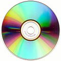
CD with color spectrum with white light exposure.

A CD splits light into its individual colors / wavelengths.

A CD reflects the light beam of a laser pointer and shows several main maxima.


Cell phone displays and curtains create more complex distributions of the intensity maxima because of their 2-dimensional structure. While displays act as reflective grids, curtains act like a transmission grille. Point-shaped light sources, when reflected on a mobile phone display, produce a distribution of the intensity maxima that is dependent on the pixel arrangement.

Observable distribution of the intensity maxima on a mobile phone display.

Maximum intensity when looking at an almost punctiform light source through a close-meshed curtain.


Web links
Individual evidence
- ↑ Klaus Hentschel: On the interplay of instrument, experiment and theory. Redshift in the solar spectrum and related spectral shift effects from 1880 to 1960 . Kovac, Hamburg 1998, ISBN 978-3-86064-730-1 , p. 84-95 .
- ^ Deborah J. Warner: Lewis M. Rutherfurd: Pioneer Astronomical Photographer and Spectroscopist . In: Technology and Culture . tape 12 , 1971, p. 190-216 .
- ^ Deborah J. Warner in: The Michelson Era in American Science 1870-1930. American Institute of Physics, New York, S. 2-12 .
- ↑ George Sweetnam: The Command of Light: Rowland's School of Physics and the Spectrum . American Philosophical Society, Philadelphia 2000.
- ^ Klaus Hentschel: The discovery of the redshift of solar Fraunhofer lines by Rowland and Jewell in Baltimore around 1890 . In: Historical Studies in the Physical and Biological Sciences . tape 23 , no. 2 . Berkeley 1993, p. 219–277 ( uni-stuttgart.de [PDF]).
- ↑ Light diffraction at the multiple slit. Retrieved July 26, 2016 .