
Moving coil measuring mechanism
In electromechanical measuring devices, a moving-coil measuring mechanism is the preferred core piece for measuring the strength of electrical currents . Electrical voltages can also be measured directly through a corresponding high-resistance design of the coil . The moving-coil measuring mechanism is basically an advanced design of a galvanometer and was developed by Edward Weston in 1888 . It shows the current intensity as a pointer deflection proportional to the measuring current in front of a scale . So that the reading of the scale display can be as precise as possible, the scale is often designed as a mirror scale . The moving coil relay is a special design in which the pointer and the scale are replaced by electrical contacts like a relay and are closed or opened at certain angular positions of the coil.
In practical use, the moving coil measuring device has meanwhile been largely replaced by digital measuring devices such as the digital multimeter . In the case of time-variable measured variables, however, it is still important due to its integrating display ( sluggish pointer deflection, depending on the accelerated mass).
construction


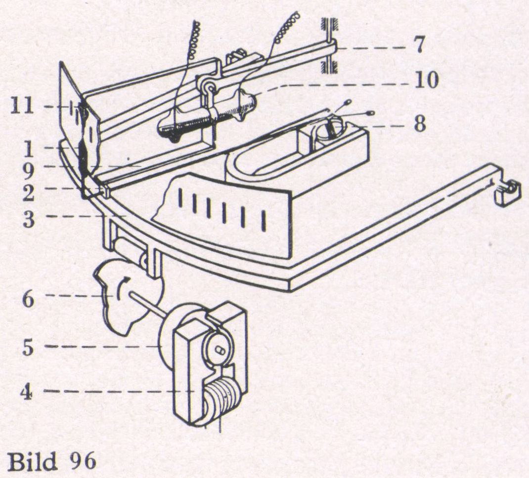
A rotatable coil (7) made of copper wire is located in the field of a permanent magnet (2). Two spiral springs (6) are used both to supply power and to return to the rest position.
Axially tensioned torsion bands serve as suspension, to produce the restoring force and to supply power in the case of tension band mounting. Moving coil measuring devices of this type do not require any tip bearings for the moving coil and are therefore free from errors due to static friction. The point bearing is more common, see figure, which is mechanically much more robust.
The coil is usually wound on an aluminum frame, which at the same time forms a short-circuit winding and dampens the measuring mechanism so that the display angle is reached with little overshoot after a very short time. To protect sensitive measuring devices during transport, they are also short-circuited in order to further increase the attenuation due to the counter-voltage during self-induction . In moving coil measuring mechanisms, the permanent magnet is either in a horseshoe shape on the outside, while a soft iron core is arranged in a cylindrical shape in the coil, or the magnet is inside the moving coil (core magnet; see picture ) and the magnetic circuit is in the form of a ring made of soft magnetic material outside the coil closed.
Pole shoes and iron core ensure that the moving coil is always in a sufficiently equally strong field in the intended range of rotation (approx. 90 °) so that the deflection is proportional to the measuring current.
Larger angles of rotation (around 270 °) can be achieved by moving the flat rotating coil on a pole piece designed as a ring, opposite which the axially magnetized ring magnet is parallel.
In the so-called moving - coil measuring mechanism , a permanent magnet is drawn in a straight line against the force of a spring into a coil through which the rectified current flows. The different principle (it is not electrodynamic, but electromagnetic) is used in two-pole voltage detectors, where the only thing that is needed is to differentiate between certain expected voltage values (e.g. 110 V, 230 V and 380 V).
function
If current is passed through the coil via the connection terminals and the springs or tensioning straps, the Lorentz force acts on the conductors of the coil located in the air gap . As a result, the coil body rotates in the field of the magnet against the force of the springs until the torque from the Lorentz force is equal to the torque from the angle-dependent restoring force of the spiral springs.
In this position the coil stops and the pointer (12) attached to it indicates the corresponding value of the current on a scale (4). After switching off the current, the springs return the pointer to the zero position (9). Since the spring force is proportional to the angle of rotation ( Hooke's law ) and the Lorentz force is proportional to the current intensity, the result is a linearly divided scale over an angle of rotation of approximately 90 °.
The following torques are then the same in equilibrium:


The equation for the pointer deflection results from:

Here, the number of turns of the coil, the radius or the diameter, the coil height, and resultantly the surface of the coil (that is, time ), and the electric current, the magnetic flux density in the air gap, the spring constant and the angle between pointer movement and rest position, .


A moving-coil measuring mechanism works polarity-dependent, i. H. when reversing the polarity of the current, the pointer deflects in the other direction. With this behavior, only direct current can be measured; to measure alternating current , a rectifier must be connected upstream in order to measure the rectified value thus formed .
Due to mechanical inertia, the pointer cannot follow a rapid change in current. In the case of alternating current above a certain frequency, around 10 Hz or more, the measuring mechanism forms the equivalent of the current, which means that it indicates zero. This behavior is in contrast to the moving iron measuring mechanism , which uses the reluctance force to display the root mean square value , i.e. the effective value .
With some measuring mechanisms, the zero, i.e. the pointer rest position of the moving coil, is in the middle of the scale or the rotating range, so that currents of both polarities can be displayed. If the zero is at the edge of the scale, the measuring mechanism can only be used for one polarity.
application areas

In recent years, analog measuring devices have been replaced by digital measuring devices such as digital multimeters in many fields . Moving coil measuring devices are the best-known example of application in analog multimeters .
A circle with a diagonally drawn arrow serves as a general circuit symbol. If the quantity to be measured is to be specified directly, write its unit or sometimes its symbol in the circle instead of the arrow.
Current measurement
Moving coil measuring devices can be manufactured down to the measuring range end value of about 10 µA. For higher currents of up to around 100 mA, the moving coil is made from thicker wire with fewer turns - the voltage drop is then correspondingly lower.

For still larger currents is a shunt used - a switched parallel to the measuring mechanism measuring resistor , which passes around a portion of the current to the measuring element ( power divider ). A series resistor is also required for the measuring mechanism so that the temperature dependency of the resistance of the copper coil has only a slight influence on the current division, for details see under ammeter . Typical arrangements for current measurement with shunt are designed for a voltage drop of 60 mV at the end of the measuring range and in this respect are superior to many digital current measuring devices, which usually have a voltage drop of 200 mV.
Voltage measurement
If a moving-coil measuring mechanism is to be used for voltage measurement, particularly current-sensitive measuring mechanisms are used. Due to the temperature dependence of the coil resistance, the current and thus the display at constant voltage are reduced by the self-heating alone. To reduce this influence, a series resistor is always required here too ; for further details see under voltage measuring device . This gives you the smallest possible voltage measuring range . For higher voltages, the minimum required value is increased; an increased proportion of the voltage drops across the series resistor of the voltage divider . Despite the measuring mechanism, which is sensitive to current, the scale is labeled in units of voltage. There is also a linear scale for the voltage measuring range.


Other measurands
In measuring and testing devices in which current or voltage is supplied directly by a sensor or by means of an electronic circuit, moving-coil measuring devices are used to display the variable to be measured. Examples are resistance measuring devices, battery test devices, temperature measuring devices and level indicators such as the VU meter .
Drop handle regulator
Drop bow regulators served as two-point regulators and consisted of a large moving-coil measuring mechanism and mechanical pointer scanning. A bracket that periodically depressed the pointer and angle-adjustable tilt switch were used for this purpose . Outside of the sampling phase, the pointer could move freely. Later the pointer was scanned without force using inductive proximity switches.
Error limits
To identify a possible measurement deviation , a class symbol of an accuracy class is often given, which indicates the error limits under certain conditions. Typical values of the class symbol are between 0.5 and 2.5.
Example: A measuring device of accuracy class 1 has positive or negative measuring errors of a maximum of 1% of the measuring range end value . If the measuring range is set to 30 V, the absolute error limits are 1% · 30 V = 0.3 V over the entire measuring range. Depending on the operating conditions, the error limits can be several times greater.
In addition, the operating position (horizontal or vertical) is indicated.
Individual evidence
- ↑ Patent US381304 : Electrical coil and conductor. Published April 17, 1888 , inventor: Edward Weston.
- ↑ http://www.sifam.com/meters.asp
- ↑ http://www.historische-messtechnik.de/images/hb_mess_1941-96.jpg A. Kusdas: Sketch of a historical drop bar regulator, accessed on October 31, 2018