
Mixer (electronics)
Mixer ( English mixer ) are in the communication technology to frequency conversion ( English frequency conversion ) used by electrical signals. They consist of electronic components such as diodes and transistors . In the context of digital signal processing , mixers can also be simulated using software in a signal processor .
This is to be distinguished from the additive combination of different signal sources in a mixer - with this, frequency conversion is usually undesirable, except for special effects.

General
With the help of mixers, a specific frequency band with a defined bandwidth can be converted into a higher or lower frequency band. In addition to the mixer, a local oscillator is required for this frequency conversion , the frequency of which determines the center frequency during the mixing. This frequency conversion is used, for example, in multi-stage radio devices in order to convert a modulated signal from a frequency range, the so-called intermediate frequency range, into the higher-frequency range actually intended for radio transmission. In the case of multi-stage radio receivers, which are also referred to as heterodyne receivers , the conversion takes place in the opposite direction by means of a mixer in a low-frequency intermediate frequency range and subsequent demodulation to obtain the transmitted useful signal.
The reason for using one or more mixer stages in radio equipment is the higher selectivity that can be achieved in comparison to straight-ahead receivers without a mixer stage. Furthermore, it is technically not possible to realize receiving devices with high selectivity in frequency ranges from a few GHz upwards without using mixer stages and the methods with multi-stage frequency conversions. An example of such a mixer, which is usually located outside the actual receiving device, are the low-noise signal converters (LNB) which are mounted directly in the focal point of the parabolic antennas for satellite reception . This mixer stage converts the received signal into a significantly lower intermediate frequency range, which is conducted to the receiving devices via coaxial cable .
Another application of mixer stages is the implementation of frequency bands in relay stations such as those represented by broadcast satellites. The reception frequency band , which is transmitted from the ground station to the satellite and is referred to as the uplink , is converted into a different frequency range in a mixer in the satellite and then broadcast by the satellite as a so-called downlink . Mixer stages and their junction field effect transistors with working ranges up to a few 100 GHz are made from semiconductor materials with high electron mobility such as gallium arsenide .
The demarcation from modulation is determined by the fact that during modulation, a low-frequency useful signal influences the amplitude and / or the phase position of a higher-frequency carrier oscillation . During the mixing, a certain frequency range is changed in its center frequency position, ideally without changing the signal components in this frequency band.
Principle of a mixer


A mixer processes two input signals:
- The "input signal" with the frequency f e . This signal is the information carrier, it contains the useful information in the form of a modulation.
- The oscillator signal with the frequency f LO . This oscillator generates a sine or square wave signal depending on the application.
The mixer uses this to produce an output signal that always contains several frequencies. Two parts, the two “sidebands”, are desirable. They contain the modulation of the signal to be converted, but have different frequencies. As a rule, only one of the sidebands is passed through a bandpass to the subsequent amplifier stages. However, depending on the quality, the mixer also generates other frequency components of different amplitudes, which are referred to as undesired mixing products and must also be suppressed.
The upper picture shows the frequency spectrum of a high quality push-pull mixer made of two field effect transistors . Both input frequencies f e = 34 kHz and f LO = 653 kHz do not reach the output because of the symmetry of the circuit. There you can only measure the harmonics , i.e. the double frequencies and the two sidebands with the frequencies f LO + f e = 687 kHz and f LO - f e = 619 kHz. In an ideal multiplying mixer, only the two sidebands would be present.
The picture below shows the spectrum that an electron tube as a mixer generates from the same input signals due to their differently curved characteristic . The two strongest, unwanted components are the input frequencies f e and f LO . In addition to their harmonics, the high harmonic distortion of electron tubes creates other undesirable mixing products in this mixer type , some of which are very close to the desired sidebands and have to be suppressed by increased filter expenditure.
Working principle
In the case of mixing stages, a distinction is made between additive mixers and the large range of differently implemented multiplicative mixing stages. Since the multiplicative mixer stages represent the usual implementation variant, the term mixer stage is generally understood to mean a multiplicative mixer stage.
The following terms and abbreviations are used to differentiate:
- The intermediate frequency ( IF or English: intermediate frequency , IF frequency ) with the symbols f ZF is the lower frequency carrier.
- The high frequency ( HF or English: radio frequency , RF-Frequency ) with the symbol f HF is the higher carrier frequency.
- The local oscillator frequency ( LO frequency or English local oscillator frequency ) with the symbols f LO corresponds to the frequency offset of the implementation.
The signals are accordingly referred to as IF , HF and LO signals ( s IF , s HF and s LO ). Instead of the frequency f , the notation with the circular frequency is also common , depending on the context .

Additive mixture

With additive mixing, the intermediate frequency is added to the local oscillator frequency and then distorted on a component with a non-linear characteristic . Due to the non-linear distortion, the sum of the two individual frequencies results in a large number of mixed frequencies which are suitably filtered by a downstream bandpass filter.
Diodes with an exponential characteristic can be used as non-linear components in additive mixer stages . The number of undesired frequencies can be minimized if a component with a square characteristic is used instead, for example a field effect transistor . To set the operating point of this component, the summand U 0 , which is constant over time, is also provided in the mapping of the adder stage . Due to the fact that the additive mixing has a non-linear transfer behavior in the overall function and in contrast to the multiplicative mixing, intermodulation distortions occur with the additive mixing of modulated signals .
The cause of the frequency diversity can be explained mathematically: The input signal is the sum of two frequencies

The relationship between the output voltage y and the input voltage x of an amplifier and some other components such as diodes can be approximated with a Taylor series :

Here is a the gain or attenuation factor.
- In the case of a component with a linear characteristic curve, b = c = d = 0, which is why no mixing frequencies are generated.

- For a FET, b ≠ 0 and c = d = 0, the power series becomes a little longer:
- The binomial formula gives the term "double product", which causes the mixture (none of the others are of interest here):


The output voltage is the superposition of sum and difference frequency . These are separated by a band pass .

- In the case of "crooked" characteristic curves (tube mixer), c ≠ 0, so another term is added:

This is somewhat tedious to evaluate and provides combination frequencies that are usually undesirable and are referred to as intermodulation .
Multiplicative mix

The functional principle of a multiplicative mixer like the Gilbert cell or ring mixer is based on the fact that two input signals are multiplied together. The mathematical background are the addition theorems of trigonometry:
![a_1 \ cos {\ left ({\ omega} _ \ mathrm {e} t + {\ varphi} _ \ mathrm {e} \ right)} \ cdot 2a_2 \ cos {\ left ({\ omega} _ \ mathrm { LO} t \ right)} = a_1 a_2 \ left [\ cos {\ left (\ left ({\ omega} _ \ mathrm {e} + {\ omega} _ \ mathrm {LO} \ right) t + {\ varphi} _ \ mathrm {e} \ right)} + \ cos {\ left (\ left ({\ omega} _ \ mathrm {e} - {\ omega} _ \ mathrm {LO} \ right) t + {\ varphi} _ \ mathrm {e} \ right)} \ right]](https://wikimedia.org/api/rest_v1/media/math/render/svg/082d737e9bbeaa608c339715a05e0b858ba26993)
With

The result is a sum and difference of the two frequencies, which can be separated by a downstream bandpass filter . The multiplicative mix is ideally linear. In contrast to additive mixing with a subsequent non-linear element, no intermodulation products occur. In real mixer stages, non-linear distortion cannot be avoided, as saturation effects or asymmetries occur in electronic switches, for example.
- Input signals and mixed product

First frequency with 1404 kHz
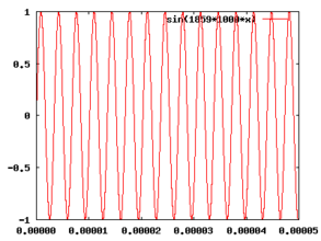
Second frequency with 1859 kHz

Product of the mixing stage


In the above illustration, two individual frequencies with f 1 = 1404 kHz and f 2 = 1859 kHz are shown over time. For example, in a radio receiver f 1 can be the oscillation generated by a local oscillator, f 2 the carrier frequency received from a radio transmission . The resulting product of the two frequencies is also shown. The low frequency component f 2 - f 1 with 455 kHz is clearly visible and superimposed on the upper frequency component f 2 + f 1 with 3263 kHz. The low frequency component f 2 - f 1 at 455 kHz is then separated from the higher frequency component in a heterodyne receiver by the following IF filter and, at 455 kHz, represents an intermediate frequency common in shortwave receivers, for example .
The multiplicative mixing is particularly easy if a square wave is used for the local oscillator frequency , since in this case the multiplication can be reduced to the values 0 and 1 , or alternatively as a bipolar signal with −1 and +1 . These mixers can be implemented with switches such as diodes or with different types of transistors , as shown in the following chapters.

Ring modulator

Symmetrical diode mixers are characterized by low noise and low intermodulation; if the local oscillator has a sufficiently high power, they can also process significantly higher input voltages than other mixers. The two input frequencies f 1 and f 2 do not appear in the output signal, which makes the subsequent filtering easier. Ring modulators are mostly used at higher frequencies because the two transformers are then small. FET mixers, which use field effect transistors instead of diodes as controlled switches, outperform the data of diode mixers in terms of large-signal behavior, despite reduced power consumption.
Ring modulators are also used in musical instruments and for speech distortion ( vocoders ).
Gilbert cell
The Gilbert cell represents a multiplicative mixer which, due to its structure and the lack of inductive components , can be implemented particularly easily in integrated circuits . The Gilbert cell is also used in voltage-controlled amplifiers.
The SO42P was one of the early integrated circuits with a balanced mixer stage. The Gilbert cell contained in it can in principle process signals down to DC voltages. Other similar circuits are e.g. B. the NE612 , which also contains an oscillator, or various AM receiver ICs, which also contain all other functionalities (e.g. regulated IF amplifier).
If the Gilbert cell is overdriven in all inputs, its behavior corresponds to the exclusive-or gate of digital technology, which is much simpler and has to be operated with square-wave signals. If one input is fed with 5 MHz and the other with 4.9 MHz, the very complex output signal also contains the difference frequency 0.1 MHz. A low pass filter can remove the other, unwanted components.
Gilbert cells can be used up to signal voltages of 25 mV, whereas ring mixers and FET switches are only overdriven at input voltages above 1 V.
Mixing with a rectangular LO signal


The signal from the local oscillator s LO can be unipolar (0… 1) or bipolar (−1… 1).
| Unipolar | Bipolar |
|---|---|
| With "on switch" ( pull-up ) | With logic non-gate and changeover switch |
 |
 |
| With "off switch" ( pull-down ) | With cross changeover switch or two changeover switches |
 |
 |
The Fourier series result for square-wave signals :
![{\ displaystyle s _ {\ mathrm {LO}} (t) = {\ begin {cases} {\ frac {1} {2}} + {\ frac {2} {\ pi}} \ sum \ limits _ {n = 0} ^ {\ infty} {\ frac {\ left (-1 \ right) ^ {n}} {2 \ cdot n + 1}} \ cos \ left [\ left (2n + 1 \ right) \ cdot \ omega _ {\ mathrm {LO}} \ cdot t \ right] & {\ text {unipolar}} \\ {\ frac {4} {\ pi}} \ sum \ limits _ {n = 0} ^ {\ infty} {\ frac {\ left (-1 \ right) ^ {n}} {2 \ cdot n + 1}} \ cos \ left [\ left (2n + 1 \ right) \ cdot \ omega _ {\ mathrm {LO}} \ cdot t \ right] & {\ text {bipolar}} \ end {cases}}}](https://wikimedia.org/api/rest_v1/media/math/render/svg/cea03c8ceec1f088303127f8f4cb70d811cf9402)
There are only odd multiples of the LO frequency. For a modulated IF signal
![s_ \ mathrm {ZF} = a (t) \ cos \ left [\ omega _ \ mathrm {ZF} \ cdot t + \ varphi (t) \ right]](https://wikimedia.org/api/rest_v1/media/math/render/svg/bb9c92d4aac63daec9d0cd8f63721e18862d4a6c)
obtained by multiplying with the unipolar square wave signal at the output:

![\ frac {a \ left (t \ right)} {2} \ cos \ left [\ omega _ \ mathrm {ZF} \ cdot t + \ varphi \ left (t \ right) \ right]](https://wikimedia.org/api/rest_v1/media/math/render/svg/388fd48292662c5296766f50e4146b76b305541a)
![{\ displaystyle {} + {\ frac {a \ left (t \ right)} {\ pi}} \ left \ {\ cos \ left [\ left (\ omega _ {\ mathrm {LO}} + \ omega _ {\ mathrm {ZF}} \ right) \ cdot t + \ varphi \ left (t \ right) \ right] + \ cos \ left [\ left (\ omega _ {\ mathrm {LO}} - \ omega _ {\ mathrm {ZF}} \ right) \ cdot t- \ varphi \ left (t \ right) \ right] \ right \}}](https://wikimedia.org/api/rest_v1/media/math/render/svg/6e3f24463408a18b67427ac44175e5ca8f9b91c3)
![{} - \ frac {a \ left (t \ right)} {3 \ cdot \ pi} \ left \ {\ cos \ left [\ left (3 \ cdot \ omega _ \ mathrm {LO} + \ omega _ \ mathrm {ZF} \ right) \ cdot t + \ varphi \ left (t \ right) \ right] + \ cos \ left [\ left (3 \ cdot \ omega _ \ mathrm {LO} - \ omega _ \ mathrm {ZF } \ right) \ cdot t- \ varphi \ left (t \ right) \ right] \ right \}](https://wikimedia.org/api/rest_v1/media/math/render/svg/7278c7fb8ba99a2c65f3b452e147a0b68b1efa2b)

For the bipolar square-wave signal, according to the coefficient comparison of the Fourier series expansion, the direct component and thus the first term of the mixed signal are omitted and at the same time the amplitude [ a ( t ) bi = 2 · a ( t ) uni ] of all alternating components doubles .

Areas of application
Since a mixer stage generates various sum and difference frequencies, a distinction is made between up-mixing and down-mixing, depending on the application and type of filter.
Up mixer

With the up-converter, the IF signal is applied to the input and multiplied by the LO signal.
![{\ displaystyle s _ {\ mathrm {ZF}} (t) = i (t) \ cdot \ cos {\ left ({\ omega} _ {\ mathrm {ZF}} \ cdot t \ right)} - q (t ) \ cdot \ sin {\ left ({\ omega} _ {\ mathrm {ZF}} \ cdot t \ right)} = a (t) \ cos {\ left [{\ omega} _ {\ mathrm {ZF} } \ cdot t + {\ varphi} (t) \ right]}}](https://wikimedia.org/api/rest_v1/media/math/render/svg/4bc6913580c438b18826d67897a356f2eadeaef0)

- In the following, only the representation with the amplitude modulation and the angle modulation is given, since this is shorter than the representation with the quadrature components.


The HF signal s HF is obtained at the output .
![s_ \ mathrm {HF} (t) = s_ \ mathrm {ZF} (t) \ cdot s_ \ mathrm {LO} (t) = a (t) \ cos {\ left [{\ omega} _ \ mathrm {ZF } \ cdot t + {\ varphi} (t) \ right]} \ cdot 2 \ cos {\ left ({\ omega} _ \ mathrm {LO} \ cdot t \ right)}](https://wikimedia.org/api/rest_v1/media/math/render/svg/082efed55681ab0820aa53be2b8c6c9304654fe7)
![{\ displaystyle {\ begin {matrix} s _ {\ mathrm {HF}} (t) = {} & \ underbrace {a (t) \ cos \ left [\ left ({\ omega} _ {\ mathrm {LO}} } + \ omega _ {\ mathrm {ZF}} \ right) \ cdot t + \ varphi (t) \ right]} & {+} & \ underbrace {a (t) \ cos \ left [\ left ({\ omega } _ {\ mathrm {LO}} - \ omega _ {\ mathrm {ZF}} \ right) \ cdot t- \ varphi (t) \ right]} \\ {} & {{\ text {upper band}} \ left (f> f _ {\ mathrm {LO}} \ right)} & {} & {{\ text {sub-band}} \ left (f <f _ {\ mathrm {LO}} \ right)} \\ {} & {\ text {in equal position}} & {} & {\ text {in reverse position}} \ end {matrix}}}](https://wikimedia.org/api/rest_v1/media/math/render/svg/e0b8a521b7f6da56e525faf98211aca613a10a48)
The portion referred to as the upper band has the same frequency sequence as the IF signal ( f LO + f IF ). This is known as equality . The sub-band has a frequency sequence that is inverted to the IF signal ( f LO - f IF ). This is called the upside down . Each of these bands can be used as an output signal, the other is suppressed with a filter. Up-converters are used in transmitters and in chopper amplifiers .
Down mixer

.svg)
With the down mixer, an RF signal is applied to the input and multiplied by the LO signal.
![s_ \ mathrm {HF} (t) = a (t) \ cos {\ left [{\ omega} _ \ mathrm {HF} \ cdot t + {\ varphi} (t) \ right]}](https://wikimedia.org/api/rest_v1/media/math/render/svg/4801475a4ff3c08967f7f11283ad89c34708c74c)
The signal s M is obtained at the output :
![s_M (t) = s_ \ mathrm {HF} \ left (t \ right) \ cdot s_ \ mathrm {LO} (t) = a (t) \ cos {\ left [\ omega _ \ mathrm {HF} \ cdot t + \ varphi (t) \ right]} \ cdot 2 \ cos {\ left (\ omega _ \ mathrm {LO} \ cdot t \ right)}](https://wikimedia.org/api/rest_v1/media/math/render/svg/d09993cc78efa29810b00186ff666e3f7bd293fe)
![{\ displaystyle s _ {\ mathrm {M}} (t) = {\ begin {cases} {\ begin {matrix} a (t) \ cos \ left [\ left (\ varpi _ {\ mathrm {HF}} + \ omega _ {\ mathrm {LO}} \ right) \ cdot t + \ varphi (t) \ right] \\ {} + a (t) \ cos \ left [\ left (\ varpi _ {\ mathrm {HF}) } - \ omega _ {\ mathrm {LO}} \ right) \ cdot t + \ varphi (t) \ right] \ end {matrix}} & {\ rm {equal position}} \, (f _ {\ mathrm {HF} }> f _ {\ mathrm {LO}}) \\ {\ begin {matrix} a (t) \ cos \ left [\ left (\ varpi _ {\ mathrm {HF}} + \ omega _ {\ mathrm {LO }} \ right) \ cdot t + \ varphi (t) \ right] \\ {} + a (t) \ cos \ left [\ left (\ varpi _ {\ mathrm {LO}} - \ omega _ {\ mathrm {HF}} \ right) \ cdot t- \ varphi (t) \ right] \ end {matrix}} & {\ rm {Kehrlage}} \, (f _ {\ mathrm {LO}}> f _ {\ mathrm { HF}}) \ end {cases}}}](https://wikimedia.org/api/rest_v1/media/math/render/svg/28f4c9063a701cf4d530e59c45c98ac91b302369)
If the HF frequency is greater than the LO frequency, an IF signal in the same position with the same frequency sequence is obtained. Otherwise an inverted IF signal with an inverted frequency sequence. The signal s M is composed of the signal s ZF (left) and a signal with f HF + f LO (right). The latter is not needed and is removed with a filter.
Down mixers are used in receivers ( radio reception , cell phones , satellite receivers ) that work on the superheterodyne principle, as well as in FM radar receivers and speed control devices.
Image frequency

When downmixer often the case occurs that the applied at the RF input signal in addition to the desired reception frequency with a image signal with the image frequency is received, because it also to f IF is decreased. In this case, the mixer works in the same and inverted position simultaneously.


Normally, one or more tunable pre-circuits attenuate the image frequency to such an extent that interference only occurs with strong transmitters on the image frequency. The lower the IF frequency, the more difficult this preselection is, since the receiving and image frequencies are then relatively close to one another (distance 2 · f IF ). One would also like to keep the expenditure of tunable circles low.
With digital mixers or the phase method, it is possible to largely suppress the image frequency even without a filter ( digital down converter ).
literature
- Ulrich Tietze, Christoph Schenk: Semiconductor circuit technology . 12th edition. Springer, 2002, ISBN 3-540-42849-6 .
- Otto Zinke, Heinrich Brunswig: High Frequency Technology 2 . Ed .: Anton Vleck, Hans Ludwig Hartnagel. 4th edition. tape 2 .. Springer, 1993, ISBN 3-540-55084-4 .
- Ekbert Hering, Klaus Bressler, Jürgen Gutekunst: Electronics for engineers and natural scientists . Springer Verlag, Berlin / Heidelberg 2014, ISBN 978-3-642-05499-0 .
- Burkhard Kainka, Herbert Bernstein: Basic knowledge of electronics. The basics for hobby - education and work, Franzis Verlag, Poing 2011, ISBN 978-3-6456-5072-4 .
- Dieter Sautter, Hans Weinerth: Lexicon Electronics and Microelectronics. 2nd edition, Springer Verlag, Berlin / Heidelberg 1997, ISBN 978-3-5406-2131-7 .
- Holger Heuermann: high frequency technology. Components for high-speed and high-frequency circuits. 2nd Edition. Vieweg + Teubner-Verlag, Wiesbaden 2009, ISBN 978-3-8348-0769-4 .
Web links
- Mixing principles (accessed September 14, 2017)
- Mixer (accessed September 14, 2017)
- Active high-performance mixer solves design problems of RF transmitters (accessed September 14, 2017)
- Frequency converter (accessed September 14, 2017)
supporting documents
- ↑ Otto Zinke, Heinrich Brunswig: High frequency technology 2 . Ed .: Anton Vleck, Hans Ludwig Hartnagel. 4th edition. tape 2 .. Springer, 1993, ISBN 3-540-55084-4 .
- ↑ Script on the topic of mixer (PDF)