
Rotation of a body as a sequence of three individual rotations around its body axes z, x ', z ".
Own coordinate system:
red Fixed reference system:
blue
The Euler angles (or Euler angles ), named after the Swiss mathematician Leonhard Euler , are a set of three angles that can be used to describe the orientation (rotational position) of a solid body in three-dimensional Euclidean space . They are usually referred to with or with . The body can be, for example, a top (in theoretical physics) or a vehicle, a ship or an airplane. In astronomy, the "body" can also be the orbit ellipse of a celestial body.


Instead of the rotational position of a body, Euler angles can also describe the position of a Cartesian coordinate system in relation to another Cartesian coordinate system and are therefore used for coordinate transformations . The rotated coordinate system is often "attached" to a rotated body. One then speaks of the body-fixed coordinate system and calls the original coordinate system fixed in space .
The rotational position is produced by the body from its original position out successively by the three Euler angles to coordinate axes rotated is. There are various conventions for choosing the axes:
-
Actual Euler angles: The first and third rotations take place around the same coordinate axis (e.g. rotation around the z-axis, x-axis, z-axis).
-
Cardan angle or Tait-Bryan angle : All three rotations are rotated around different coordinate axes (e.g. in the order x-axis, y-axis, z-axis).
Either the second and third rotations rotate around the previously rotated coordinate axes ( intrinsic rotations) or always around the original coordinate axes ( extrinsic rotations).
The rotation made up of the three individual rotations can be described by a matrix that can be represented as the product of three elementary rotation matrices . Depending on the application, different matrices are considered:
-
Transformation matrix for the coordinate transformation from the rotated (body-fixed) to the original (space-fixed) coordinate system,
- Transformation matrix for the coordinate transformation from the spatially fixed to the body fixed coordinate system,
-
Mapping matrix of the rotation with respect to the spatially fixed coordinate system.
history
Rotations have been described by three angles since around 1600 at the latest. Thus, certain Johannes Kepler in the Astronomia Nova the Mars orientation of the web with respect to the ecliptic by three angles. An algebraic description with which the rotational position of any point could be calculated was only formulated in increasing depth by Leonhard Euler from 1775 . In the first work he showed that the nine coefficients corresponding to the elements of the mapping matrix are not independent of each other because of the length accuracy of a movement , but are determined by only three independent angles. However, these are not the Euler angles dealt with here, but pure arithmetic variables without geometric significance. This work is particularly well-known today because in an addition he proved the rotation theorem named after him , according to which every movement with a fixed point is a rotation around an axis. The mapping equations resulting from this result, in which a rotation is parameterized by the direction cosine of the axis of rotation and the angle of rotation, he found in a second work shortly thereafter.
In a third, posthumously published work, he finally introduced three angles , and , with which he described the transformation from body-fixed to spatial coordinates and which, except for signs and additive constants, correspond to the angles named after him today. His approach differed significantly from the method used today, in which one coordinate system is converted into the other coordinate system by three successive rotations around the coordinate axes. Euler argues similarly to the first paper, but comes to a more favorable approach with the three angles , and because here - in modern parlance - he used not only the orthonormality of the rows but also that of the columns of the transformation matrix. In order to clarify their geometrical meaning he looked at the intersection points , , the spatially-fixed coordinate system with the unit sphere and the corresponding intersection points , , of the body-fixed system, and showed that the cosines of the sheets , , ..., just the coefficients of the transformation equations. So it is the angle between the - and the - axis. In addition, spherical trigonometry shows that the angle at is in the spherical triangle and the angle at is in the spherical triangle . Today the corresponding angles are not measured from the plane, but from the nodal line perpendicular to it ; the relationship with the Euler angles most commonly used today for the rotation sequence xyx is given by , and .


Lagrange brought
two derivatives of the transformation equations in the Mécanique Analytique published in 1788 . The first is essentially identical to that of Euler, except for the names of the angles (he calls them , and ). The second is in line with the modern, treated in detail below representation for the zxz-rotation sequence - again with different angle names ( , , ).


Actual Euler angles

Coordinate transformation, turning sequence in standard x-convention
blue : coordinate system in initial position
green : intersection line of the xy planes, intermediate position of x-axis
red : coordinate system in target position
In the following, as in the graphic opposite, the axes of the coordinate system in the starting position (blue in the graphic) are designated with the lower case letters , and , the axes in the target position (red in the graphic) with the corresponding capital letters , and .


Geometric description
The - -plane and the - -plane intersect in a straight line (node line). This is perpendicular to the -axis and on the -axis.
- The first Euler angle (also ) is the angle between the -axis and the straight line (measured in the direction of the y-axis).


- The second Euler angle (also ) is the angle between the -axis and the -axis.


- The third Euler angle (also ) is the angle between and the axis.


The described version of the Euler angles, wherein the angle of the axis from the line of nodes and the angle of the line of nodes to the measured axis, is called the standard x-Convention . Accordingly, with the standard y-convention, the angles are measured from the -axis to the node line and from the node line to the -axis.
In physics, the standard x convention is mostly used. Instead here , and the angles are usually with , and referred.
Description by intrinsic rotations
The rotation that turns the system into the system can be split into three rotations. With the standard x convention these are:


- First the rotation around the angle around the -axis,

- then the rotation by the angle around the knot line ,

- finally the rotation around the angle around the axis.

With these rotations, new coordinate systems are created one after the other:
- original coordinate system: -, - and -axis
- after the first rotation: -, - and -axis


- after the second rotation: -, - and -axis


- after the third rotation: -, - and -axis (or -, - and -axis)


The rotation around is a rotation around the -axis, the rotation around the -axis a rotation around the -axis. The total rotation is thus made up of the rotations , and :


The sequence of the axes of rotation is therefore: -axis → -axis → -axis or, for short, - - .
Such a breakdown into rotations, each of which is rotated around the co-rotated coordinate axes, is called intrinsic rotation sequence.
Description by extrinsic rotations
The same rotation can also be described by three individual rotations around the original coordinate axes. The angles remain the same, but the order of the rotations is reversed, and the intermediate layers and are different to the intrinsic rotation: First the body is rotated around the angle around the -axis, then around the -axis (the angle between the - and -axis is the same as the one between the - and the -axis, namely ) and finally by the angle around the -axis ( the -axis is rotated into the node line and the angle between and is the -axis ). An algebraic explanation can be found below in the section Matrix Derivation in the General Case . So it is


-
 .
.
Such a rotation sequence, which always rotates around the original coordinate axes, is called an extrinsic rotation sequence.
The descriptions by intrinsic and extrinsic rotations are therefore equivalent. The description by intrinsic rotations is clearer, however, while the description by extrinsic rotations is mathematically more accessible.
Description by matrices
The rotations around the Euler angles can be described with the help of rotation matrices , the entries of which are sine and cosine values of the Euler angles. A distinction is made between mapping matrices and coordinate transformation matrices . In the following these matrices are given for the standard x convention. The matrices for the standard y-convention are obtained analogously by using the rotation matrix for the rotation about the y-axis instead of the elementary rotation matrix for the rotation about the x-axis.
Mapping matrix (active rotation)
With an active rotation ( alibi rotation ) the points and vectors of the room are rotated. The coordinate system is recorded. The rotation matrix is the mapping matrix of this figure . The coordinates of the rotated vector result from the coordinates of the original point by multiplying with the rotation matrix:


The mapping matrices for rotations around the coordinate axes (elementary rotation matrices) are:

for the rotation around the angle around the -axis, the -axis and the -axis.
The rotation matrix of the composite rotation is obtained by matrix multiplication from the matrices of the individual rotations. Since the elementary rotation matrices describe the rotations around the original coordinate axes, the extrinsic rotation sequence is used
and receives the mapping matrix

Transformation matrix
Transformation matrices describe coordinate transformations from the original (fixed in space) coordinate system to the rotated (fixed in space) or vice versa. The transformation matrix for the coordinate transformation from the body-fixed coordinate system to the spatially fixed co-ordinates with the mapping matrix described above, the matrix for the reverse transformation is the transpose of this matrix. If the vector has the coordinates in the space-fixed coordinate system and the coordinates in the body-fixed system , then applies


and

Conventions
There are six different ways to choose the axes for actual Euler angles. The first and third axes are the same for all of them. The six options are:
-
- - (intrinsic) or - - (extrinsic): Standard x convention
-
- - (intrinsic) or - - (extrinsic): standard y-convention
-
- - (intrinsic) or - - (extrinsic)
-
- - (intrinsic) or - - (extrinsic)
-
- - (intrinsic) or - - (extrinsic)
-
- - (intrinsic) or - - (extrinsic)
Cardan angle
With the cardan angles (after Gerolamo Cardano ) or also Tait Bryan angles (named after Peter Guthrie Tait and George Hartley Bryan ), the three rotations take place around three different axes. As with the actual Euler angles, there are six possible rotation sequences:
-
- - (intrinsic) or - - (extrinsic)
-
- - (intrinsic) or - - (extrinsic)
-
- - (intrinsic) or - - (extrinsic)
-
- - (intrinsic) or - - (extrinsic)
-
- - (intrinsic) or - - (extrinsic)
-
- - (intrinsic) or - - (extrinsic)
Roll, pitch and yaw angles: zy′-x ″ convention
description

Rotation sequence z, y ′, x ″ (yaw- nod -roll)
blue : space-fixed coordinate system
green : y'-axis = node line N (y ′)
red : body-fixed coordinate system
Note: is negative here.
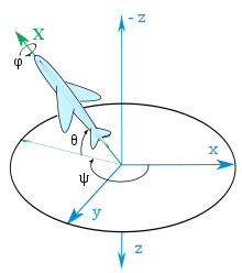
Yaw, pitch and roll angles as the attitude angle of an aircraft

The rotation sequences used and standardized in aviation, shipping and automotive engineering (aviation: DIN 9300; automotive engineering: DIN ISO 8855) belong to the group of Tait Bryan rotations. The standards are the names of yaw, pitch and roll angle (Engl. Yaw , pitch and roll angle ) required for the three Euler angles. The three rotations turn the earth- fixed system ( world frame ) into the body-fixed coordinate system ( body frame ).
Intrinsic order - - (yaw-pitch-roll angle):
- The yaw angle (also called heading or azimuth) measured in the earth-based system is used to rotate around the axis. The axis becomes the node axis . Main Range: . The direction of rotation is mathematically positive (counterclockwise)


- The pitch angle measured against the earth's surface ( - plane) is used to rotate around the node axis. The vehicle-fixed axis is created. Main Range: . The direction of rotation is mathematically positive.

- The roll angle (also called roll angle) describes the rotation around the axis fixed to the vehicle . The axles and fixed to the vehicle are created . Main Range: . The direction of rotation is mathematically positive.

Extrinsically, this corresponds to the sequence - - (roll-pitch-yaw angle).
Instead of the lower case letters , and the corresponding upper case letters , and are used.


Transformation matrices
The coordinate transformation from the body fixed to the spatial coordinate system is done by the matrix

described. The reverse transformation from the spatially fixed to the body fixed coordinate system is described by the transpose of this matrix. (Actually the inverse, but with rotating matrices the inverse is the same as the transposed matrix.)

This means: If the vector in the spatially-fixed coordinate system the coordinates , , and in the body-fixed coordinate system the coordinates , , , the following applies


and

Application example
In the earth-fixed coordinate system, the weight vector has only one component (in the direction of the center of the earth):


The transformation into the aircraft-fixed coordinate system then takes place by multiplying the earth-fixed weight vector with the transformation matrix :


In a physically correct manner, the weight force also acts backwards (in the negative direction) if the pitch angle is present in the aircraft .
Matrix derivation in the general case
For any choice of the rotation axis sequence, the resulting rotation matrix can easily be derived using the following relationship (active rotations):
The turning matrices around the global axes are known. If it is now to be rotated again around an axis that has already been rotated, then this corresponds to the rotation matrix around the corresponding global axis, but in a transformed vector base . The transformation matrix ( base change matrix ) is the previous rotation.
Let and be two rotary matrices around the two global axes and . To calculate the rotation matrix for the sequence , one observes that the rotation matrix for the second rotation must correspond to the base-transformed matrix . This gives the resulting total rotation matrix . The verification is carried out analogously for a larger number of turns.


In three active rotations (A is executed first, then B, then C) results in the total rotation matrix using , .


This representation shows that the rotation matrix for any rotation sequence in consecutively rotated axes results from the simple multiplication of rotation matrices around global coordinate axes - but in the reverse order.
Result, interpretation
The coordinate system obtained with the axes , and is the so-called body-fixed system. The angles and indicate the position of the axis in relation to the system fixed to the body (“rotation” and “tilting”); the angle describes the rotation of the body around it. The following naming conventions correspond to this:


Mathematical properties
The mapping that assigns the associated rotation matrix to the Euler angles has critical points at which this assignment cannot be locally reversed and one speaks of a gimbal lock . In the case of the above With the x or y convention, this always occurs when the second rotation angle equals zero and the rotation vector of the first rotation is the same as the rotation vector of the second rotation. But this means that there are any number of Euler angles for a rotation around the -axis .

The critical points are included in the definition of the position angle according to the aviation standard .

According to Kurt Magnus , gyro problems that are possible cannot be described with Euler angles (x-convention) and cardan angles are used instead.

Cons, alternatives
Euler angles have several disadvantages for representing rotations:
- The singularity mentioned above means that a single rotation can be expressed in terms of different Euler rotations. This leads to a phenomenon known as the gimbal lock .
- The correct combination of rotations in the Euler system cannot be specified intuitively because the axes of rotation change.
Instead of using the Euler angles, each rotation can also be specified by a vector, which indicates the position of the axis and the direction of rotation through its orientation, and the angle of rotation through its absolute value (see e.g. or orthogonal tensor ). Another way of describing the orientation and partly avoiding these disadvantages are quaternions .
Applications

Texture pole figures made of gamma-TiAl in an alpha2-gamma two-phase alloy.
In theoretical physics , Euler's angles are used to describe the rigid body . The known cardanic suspension of the technical mechanics is a practical application .
In vehicles, the Euler angles of the main positions are called roll-pitch-yaw angles .
In crystallography , the Euler angles are used to describe the circles of the single crystal diffractometer (with a cardanic suspension made up of two circles of rotation perpendicular to one another, which corresponds to the Euler angles and is called the Euler cradle) and to describe the orientation density distribution function of textures .
In astronomy , Euler's angles are known under other terms as an orbital element of an object .
In computer graphics , Euler's angles are used to describe the orientation of an object.
In solid-state NMR , the Euler angles are used for the theoretical description and for the simulation of spectra.
literature
Web links
Individual evidence
-
^
Herbert Goldstein, Charles P. Poole Jr., John L. Safko: Classical Mechanics . 3rd, complete and enlarged edition. WILEY-VCH, 2006, ISBN 3-527-40589-5 , pp. 161 ff . ( limited preview in Google Book search). : "We can carry out the transformation from one Cartesian coordinate system to another by means of three successive rotations that must take place in a certain order."
-
↑ Hui Cheng, KC Gupta: A Historical Note on Final Rotations . In: Journal of Applied Mechanics . tape 56 , no. 1 , March 1989, p. 139–145 , doi : 10.1115 / 1.3176034 ( full text [PDF; accessed December 13, 2018]).
-
↑ L. Eulerus: Formulas generales per translatione quacunque corporum rigidorum . In: Novi Commentarii academiae scientiarum Petropolitanae . tape 20 (1775) , 1776, pp. 189–207 ( E478 (full text), with English translation [PDF; accessed on December 13, 2018] translatio is any movement here ).
-
↑ L. Eulerus: Nova methodus motum corporum rigidorum determinandi . In: Novi Commentarii academiae scientiarum Petropolitanae . tape 20 (1775) , 1776, pp. 208-238 ( E479 (Scan) [PDF; accessed on December 13, 2018] the mapping equations are in §13).
-
↑ a b c Leonardus Eulerus: De motu corporum circa punctum fixum mobilium . In: Leonardi Euleri opera postuma mathematica et physica: anno MDCCCXLIV detecta . tape 2 , 1862, p. 43–62 ( E825 (scan) , accompanying images [accessed December 13, 2018]).
-
↑ a b c La Grange: Analytical Mechanics . Göttingen 1797 ( Scan [PDF; accessed on December 13, 2018] Original title: Mécanique Analytique . 1788. Translated by Friedrich Wilhelm August Murhard).
-
↑ A detailed proof can be found in: G. Fischer: Lernbuch Lineare Algebra und Analytische Geometrie. 2nd edition 2012, in 5.3.6
-
↑ Magnus, Kreisel, Springer, 1971, p. 32
-
^ Herbert Goldstein, Charles P. Poole, Jr., John L. Safko, Sr .: Classical Mechanics . 3. Edition. John Wiley & Sons, 2012, ISBN 978-3-527-40589-3 .
-
↑ Liss KD, Bartels A, Schreyer A, Clemens H: High energy X-rays: A tool for advanced bulk investigations in materials science and physics . In: Textures Microstruct. . 35, No. 3/4, 2003, pp. 219-52. doi : 10.1080 / 07303300310001634952 .
-
↑ The connection between the Euler angles and the cardanic suspension is u. a. presented in Chapter 11.7 of the following book: U. Krey, A. Owen: Basic Theoretical Physics - A Concise Overview. Springer-Verlag, Berlin 2007.
-
^ Euler-Wiege, Lexicon of Geosciences, Spectrum


.png)


