
Theodolite


A theodolite is an angle measuring instrument that is used in geodesy (surveying) to measure horizontal directions and zenith or vertical angles . For this purpose, it is set up vertically over a point using a tripod . A special form is the hanging theodolite , which is used in mining.
Essentially, a theodolite consists of a housing , the telescopic sight , a vertical and a horizontal pitch circle and one or two vials . The latter are used for the vertical alignment of the axis of rotation ( leveling ).
A crosshair is integrated into the telescopic sight , with which the target is sighted. Usually the angles set are displayed and / or saved by the device in the unit gon (100 gon = 90 °).
etymology
The origin of the word theodolite is uncertain. It may have been created by fusing the Arabic alhidate with the English the . In contrast, Engelsberger believes in his 1969 dissertation Contribution to the History of the Development of theodolite , as shortly before Peters in his contribution to the history and meaning of the word theodolite , that the term comes from the Greek, found by the Englishman Leonard Digges in an old script and for the first time in this Context was used. This explanation also seems obvious, because the three ancient Greek terms theós ( θεός 'God'), dõron ( δῶρον 'gift') and lithos ( λίθος 'stone') are combined here.
Construction
Measuring principle
By rotating and tilting the measuring telescope , the theodolite measures horizontal directions (rotation around its vertical standing axis ) and vertical angles (rotation around the horizontal tilting axis ). The angles are usually given in gons , with older instruments also in degrees (360 ° = 400 gons). Each axis of rotation has a clamping and a fine movement .
Some devices indicate the gradient in percent instead of the zenith angle . In the case of artillery , a theodolite is called a directional circle and is divided into 6400 lines instead of 400 gons .
Precursors of the theodolites were the dioptra (antiquity), the azimuthal quadrant (around 1500) and the tilting rule . Precise universal instruments were built for triangulation and astronomy from 1850 onwards. With the repetition theodolite, the measurement accuracy could be increased by adding angles. Total stations made it possible to measure distances on curves in the field of vision - which is done today with lasers and electronics.
Analactic telescope
There are several possible designs for the measuring telescope (see below). A condition for all types is an analactic telescope in which the focal point of the lens , the analactic point (reference point for angle and distance measurement ) lies exactly above the vertical axis of the theodolite.
The Italian engineer Ignazio Porro achieved this for the first time around 1860 by installing a converging lens between the lens and the crosshair. Today, it is usually as a focusing lens used instead of the former which focuser the internal focusing and a completely closed, dustproof telescope is possible.
Among the optical systems, the astronomical telescope predominated until the 1960s , although its inverted image was annoying for inexperienced observers. With a deflecting prism attached to the eyepiece, an upright but reversed image was obtained. Instead of the Porro lens (which forms a Huygens eyepiece with the eye lens ), a focusing lens served as an inverting system and turned the astronomical telescope into a terrestrial telescope . This type of construction has become the most common since Heinrich Wild's designs .
For special purposes (military, satellite telescopes ), erecting prisms such as binoculars are also installed. Astronomy also works with broken telescopes , which are mounted on the side of the tilt axis and can be swiveled to the zenith .
Substructure and horizontal circle
The theodolite substructure or limbus contains the horizontal circle (1) and the vertical axis ( standing axis ) (S). It carries the alidade (Arabic), the superstructure consisting of two supports (2), the horizontal tilting axis (K), the telescope (3), the circular reading (4) and the vertical circle (5). The telescope has a reticle (reticle in the eyepiece ), through which the sighting axis (Z) is defined, and an inner lens for focusing (focusing).
The base sits on the base plate of the stand is placed and with three leveling screws and dragonfly leveled is. The centering over the measuring point is done by moving the instrument on the horizontal tripod plate, then the heart screw of the tripod is tightened from below.
Accuracy classes
Depending on the measurement accuracy and purpose, a distinction is made between
- Building theodolite (robust and light, approx. ± 10 ")
- Total station (including distance measurement, since around 1990 mostly digital reading and automatic tilt compensation of the standing axis)
- Precision or second theodolite (± 1 ", for engineering geodesy )
- and the universal instrument (± 0.1 ", e.g. DKM3 and Wild T4 ) for astrogeodesy .
- Some passage instruments and special devices for military and satellite geodesy (e.g. the Moonwatch Apogee or the earlier Kinetheodolite ) are built similar to the theodolite .
Possible instrument failure
The four main instrument errors (adjustment or manufacturing inaccuracy, deviations from the theoretical ideal state) in theodolites are
- Sighting axis error : The optical axis of the telescope is not perpendicular to the tilt axis of the telescope.
- Tilting axis error : The tilting axis of the telescope is not perpendicular to the standing axis of the theodolite.
- Height index error : the zero mark of the vertical circle does not point to the zenith when the theodolite is leveled. If there is no height index error, the zenith direction corresponds to one leg of the zenith angle. The other leg points in the direction of the observation target.
- Circle division error: The scale division on the pitch circles usually deviates unsystematically from the ideal of even division.
Instrument errors ( precision mechanical ) can be passed through
- Eliminate measurements in two telescope positions and averaging,
- minimize repeated measurements with different pitch circle positions,
- mathematically eliminate subsequent reduction or reduce its influence and / or
- minimize high optical-mechanical precision (at least 1 µm) in the influence.
Other small influences such as thermal effects or mechanical residual stresses in the theodolite structure generally remain below 1 "and are therefore negligible.
The standing axis error , however, cannot be completely eliminated . It occurs when the standing axis is not parallel to the direction of gravity . Then the leveling is incorrect. One reason for this can be a misalignment of the instruments used for leveling. The standing axis error is an operating or installation error. Any remaining inclination of the vertical axis to the plumb line can be measured internally by a two-axis inclination sensor in modern total stations and automatically incorporated into the measurement results.
The vertical axis is at right angles to the vial axes or to several measuring directions. The sighting axis is perpendicular to the tilt axis . The tilt axis is perpendicular to the standing axis . All three axes ideally intersect at one point.
Direction measurement with theodolite or total station
Measurands
The following measurands can be observed with a theodolite:
- Horizontal angle - as the difference between the directional observations to two targets,
- Vertical angle : usually as the zenith distance (from the zenith to the measuring point), less often as an elevation angle above the horizon
- Angular differences : for distance measurement with the two distance threads (Reichenbach threads ) or with reduction tachymeters
- Measurement with a movable thread network : only for special theodolites for astrogeodesy , see impersonal micrometer .
- Electronic distance measurement : almost all modern theodolites and total stations are also equipped with a laser range finder.
Setup and direction measurement
Before the measurements, the instrument is on the stand to accurately level up , and most centrally over a ground point ( for surveying or measuring point set up). The leveling with the Alidaden vial causes the vertical axis of the instrument to coincide with the plumb line .
- Centering and leveling are carried out simultaneously according to a special, schematized procedure: either with a plumb bob that is hooked into the knurled screw ( heart screw ) of the tripod plate, or an optical plumb bob integrated in the tripod or theodolite .
- Now with the rotatable and tiltable measuring telescope (telescope with crosshairs - today: crosshairs) all points to be measured are sighted one after the other - first mostly the polygon points , then all the detail points.
- After each aiming, the direction is read off the pitch circle (angle scale fixed in the theodolite) , with additional height measurement also the zenith angle . Classic theodolites have a reading microscope for this , into which both angular positions are reflected .
- In the case of electronic theodolites and total stations, the pitch circles are automatically scanned by incremental or absolute value encoders , the angle values are converted into digits by A / D converters, displayed and saved.
Reading of the partial circles


The advantages of the automatic pitch circle reading are that the measurement is 20–50% faster, less fatigued and personal reading errors are eliminated; Errors in data acquisition are also becoming less common. However, it is important to ensure that the measuring points are coded exactly so that further digital processing can run smoothly later.
For automatic detection, the pitch circle is coded and scanned with different techniques ( optoelectronic , electrical, magnetic). Magneto-electronic scanning is also known as Inductosyn . Electrical scans are now technically obsolete. On the other hand, optical-electronic scanning methods, in which a distinction is made between transmitted-light and reflected-light technology, are widespread.
In the transmitted light method, blackening is used to code, which creates translucent and opaque areas. The coding is illuminated from one side and a photodiode as a receiver sits on the other side. In the incident light method, the transmitter and receiver are arranged on the same side. Since the pitch circle has different reflection properties, it must be possible to register light rays of different strengths. The coding disks are usually provided with a Gray code .
The angle between two target points with respect to the instrument position is now calculated from the difference between the two measured directions.
Reference directions
While the readings on the vertical circle refer to the zenith or horizon, the measurement of the horizontal angle can have different reference directions:
- the direction to any target point (e.g. the nearest polygon point or a clearly visible long-term target )
- the direction to an official fixed point whose coordinates are known: a trigonometric point (TP), a pick-up point (AP) or a switch-on point (EP). It can then be oriented to the geodetic coordinate system ( grid north )
- Oriented direction : magnetic, geographic or grid north. In the case of the former, a correction must be made; in the case of the grid north, geodetically correct direction angles are obtained from all measured directions .
The reference direction of the vertical angles is the plumb direction with correct leveling and must therefore i. d. Usually not corrected. Exceptions are poorly calibrated instruments ( horizon slope ) and in special cases deviation from the perpendicular . When the telescope is aligned horizontally, the zenith angle is exactly 100 gons (90 °), which is also known as the leveling view.
Observation and accuracy
To eliminate mistakes, the goals are measured in one sentence (sometimes in half-sentences ). One set consists of two series of measurements (2 half-sentences), whereby for the second series of measurements the telescope is knocked through (rotated around the tilt axis to the other side of the device), the superstructure is rotated by 200 gons (180 °) and the targets are aimed again. As a result, the readings of the target directions take place at diametrically opposite points on the horizontal circle and at corresponding points on the vertical circle. The influences of the target, tilting axis and height index error have the same amount in both telescope positions, but have opposite signs . When averaging the horizontal direction and the zenith angle from both telescope positions, observations are obtained that are free from the influences of axis errors. The accuracy is therefore between 0.01 mgon and 1 cgon standard deviation.
Well-known manufacturers

- FW Breithaupt & Son
- Geo-Fennel (formerly Fennel)
-
Trimble Navigation :
- Carl Zeiss (historic), incorporated into Trimble Navigation
- Geodimeter (historical), incorporated into Trimble Navigation
-
Leica Geosystems :
- Kern & Co (until 1992, then merged into Leica Geosystems)
- Wild Heerbrugg (historical), incorporated into Leica Geosystems in 1990
- Topcon
- Sokkia
Some previous manufacturers:
- Starke & Kammerer , Vienna (until around 1950)
- Miller, Innsbruck (until approx. 1990)
- Zeiss Jena (until around 1995)
- FPM-Holding (formerly VEB Freiberger Precision Mechanics )
See also: manufacturer of total stations

Theodolite, around 1810, on a Berlin welfare stamp from 1981
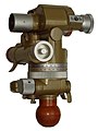
Soviet artillery district "PAB-2"

Second theodolite K1S from Kern & Co AG

Modern theodolite from Leica Geosystems
_1981,_MiNr_641.jpg)


See also
- Total station (geodesy)
- Bussolentheodolite
- Travel theodolite
- Photo theodolite
- motorized theodolite
- Kinetheodolite
- Spinning theodolite
literature
- Bertold Witte , Peter Sparla: Surveying and the basics of statistics for the construction industry . 7th edition. Wichmann, Berlin 2011, ISBN 978-3-87907-497-6 .
- Heribert Kahmen: Applied Geodesy. Surveying . 20th edition. Walter de Gruyter, Berlin / New York, ISBN 3-11-018464-8 .
Web links
- AlpenTunnel.de: A historical repetition theodolite
- Explanation of the measurement with the theodolite, material from the University of Kiel
Individual evidence
- ↑ Theodolite. In: Lueger: Lexicon of the entire technology. zeno.org, accessed on November 13, 2018 .
- ↑ Ralf Kern: Scientific instruments in their time . tape 4 : Perfection of optics and mechanics . König, Cologne 2010, ISBN 978-3-86560-868-0 , p. 480 .
- ↑ Heribert Kahme: Applied Geodesy: Surveying . 20th edition. Walter de Gruyter , Berlin 2006, ISBN 978-3-11-018464-8 , pp. 97-98 ( Google Books ).