Unified Modeling Language
| Unified Modeling Language | |
|---|---|

|
|
| Basic data | |
| Paradigms : | Modeling language |
| Publishing year: | 1990s |
| Designer: | Grady Booch , Ivar Jacobson , James Rumbaugh |
| Developer: | Object Management Group |
| Current version : | 2.5.1 (December 2017) |
| Important implementations : | Various |
| Dialects: | SysML |
| Standardizations: | * UML 2.4.1 Infrastructure Specification (English; PDF) |
| Influenced by: | OOSE , RDD , OMT , OBA , OODA , SOMA , MOSES , OPEN / OML |
| Affected: | SysML |
| Operating system : | The decisive factor is what the UML tool runs on, if it supports automatic translation, see: UML tool # source code generation and UML tool # programs |
| www.omg.org/spec/UML/ | |
The Unified Modeling Language (unified modeling language) , short UML is a graphical modeling language for specifying, designing, documentation and visualization software components and other systems. It is developed by the Object Management Group (OMG) and is standardized both by it and by ISO (ISO / IEC 19505 for version 2.4.1). In the sense of a language , UML defines identifiers for most of the terms that are important in modeling and defines possible relationships between these terms. UML also defines graphical notations for these terms and for models of static structures and dynamic processes that can be formulated with these terms.
UML is the dominant language for software system modeling today. The first contact with UML is often that UML diagrams have to be created, understood or assessed in the context of software projects:
- Project clients and specialist representatives check and confirm, for example, requirements for a system that business analysts have recorded in use case diagrams in UML;
- Software developers implement work processes that business analysts have described in activity diagrams in cooperation with specialist representatives ;
- System engineers implement, install and operate software systems based on an implementation plan, which is available as a distribution diagram.
However, the graphic notation is only one aspect that is regulated by UML. UML primarily defines which terms and which relationships between these terms are used to specify so-called models - diagrams in UML only show a graphical view of sections of these models. UML also suggests a format in which models and diagrams can be exchanged between tools.
History of origin
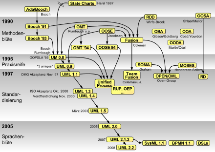
The first version of UML was created in the 1990s in response to numerous proposals for modeling languages and methods that were intended to support object-oriented software development emerging at the time. The first series of language versions, also known as UML 1.x, was replaced in 2005 by a fundamentally revised version, often referred to as UML2.
From the beginning to Unified Modeling Language 1.x
The fathers of UML, especially Grady Booch , Ivar Jacobson and James Rumbaugh , also known as "The Three Amigos", were well-known representatives of object-oriented programming in the 1990s. They had all developed their own modeling languages. When they were together at Rational Software , the idea arose to combine the various notation systems in a structured manner. A variety of different modeling languages had a direct or indirect influence on the design of UML, including OOSE , RDD , OMT , OBA , OODA , SOMA , MOSES and OPEN / OML .
As a result of these efforts, the UML was born. The standardization, maintenance and further development of the language was handed over to the OMG, which accepted the language as the standard on November 19, 1997 .
History of the Unified Modeling Language 2
In August 1999, the OMG initiated the development of UML2 by publishing a corresponding Request for Information (RFI).
A year later, in September 2000, the OMG asked its members and other interested parties for suggestions for UML2. In accordance with the new architecture defined for UML2, the OMG published three Requests for Proposals (RFP): a UML 2.0 Infrastructure RFP, a UML 2.0 Superstructure RFP and a UML 2.0 OCL RFP. Anyone wishing to submit proposals had about another year to do so.
In the first round, various groups and individuals submitted drafts. In mid-2002, these consortia had several revised and consolidated responses to individual Request for Proposals. It was not until October 2002 that all proposals for the UML 2.0 infrastructure and the UML 2.0 superstructure could be presented at the meeting of the responsible working group in Helsinki . The working group set a date for a further revised version of the proposals at the beginning of January 2003. The main difficulty now was to merge the different designs into one specification. On the one hand, there was criticism that the different philosophies in the submitted proposals would be difficult to adjust, on the other hand, in January 2003 a new consortium called 4M submitted a proposal (UML4MDA) that tried to bridge the differences between the previous specifications.
In March 2003 the responsible working group recommended the proposals of the U2 consortium for the UML 2.0 Infrastructure and for the UML 2.0 OCL for approval, in May then also for the UML 2.0 Superstructure of the same consortium, so that from June 2003 three finalization task forces of the OMG could start work to complete the part specifications. However, the task forces could not complete their work as planned by April 2004 and therefore founded a second Finalization Task Force , which was supposed to solve the remaining problems by September 2004.
In September 2004 all Finalization Task Forces were finally able to finish their work. For the UML 2.0 OCL and the UML 2.0 Infrastructure, finally accepted documents (Final Adopted Specification) were available. Only with the UML 2.0 superstructure did this last step seem to be delayed a little: in March 2005, the OMG website continued to offer only a temporary document with the informal name UML 2.0 superstructure FTF convenience document for download.
On October 21, 2008, Beta 1 of UML Version 2.2 was published by OMG, and the final version was available in February 2009. A new addition in version 2.2 is the profile diagram in order to be able to structure self-defined stereotype collections.
UML 2.3 was published in May 2010. This version mainly contained bug fixes in the metamodel and sharpening of the semantics of model elements in the UML specification document. The current version 2.5 was published in June 2015.
structuring
The scope of UML has grown continuously during the development from UML 1.0 to UML 2. Structuring is very important for the development of UML 2 as well as for the communication, application and not least for the readability of the UML 2 specification. What could be specified in a document in the first versions of UML must therefore be broken down into partial specifications for UML 2. The structure of UML 2 is described in the following sections.
Part specifications
UML2 is divided into three sub-specifications. The UML 2.0 Infrastructure Specification lays the foundation for UML2 by describing the most commonly used elements of UML2 and the model elements that specialize the remaining model elements. This document specifies concepts such as the class , the association or the multiplicity of an attribute. The UML 2.0 Superstructure Specification builds on the foundation of the UML 2.0 Infrastructure Specification and defines the model elements of UML2 that are suitable for specific purposes. Typical concepts that are specified in this document are the use case , the activity or the state machine . Finally, the document specifies entitled UML 2.0 Object Constraint Language The Object Constraint Language 2.0 (OCL2).
Another, fourth part does not deal with the semantic model of UML, but specifies the layout of the diagrams. This document is titled UML 2.0 Diagram Interchange and is a new feature in UML 2.0; UML 1.x did not have a standardized format with which the diagram layout could be exchanged between different tools. Up to now, one tool could also transfer the semantic information in a UML model to another tool; the appearance of the diagrams, i.e. the positions and sizes of individual diagram elements, was lost. Diagram Interchange (DI) aims to eliminate this shortcoming.
Metamodeling
Similar to how natural languages describe themselves in lexicons or grammars, UML was also conceived as a language tool that explains itself with some language components.
The language concepts are divided into four layers M0 to M3 .
With the Meta Object Facility (MOF), model elements of UML2 are specified and thus interchangeable with the Meta Interchange XMI format, for example . This MOF is at level M3 and represents one of the four layers. It is the metalanguage of the metalanguages (the metametamodel ) and contains basic elements (such as packages, classes, attributes and associations). The metalanguage UML2 (M2) is defined in MOF and makes the known language features available, beyond the concepts of MOF also use cases, state machines and more. The UML models created in practice are on level M1 . This shows the objects of the M0 layer. These are the specific runtime instances of the system.
As in UML2.0, UML1.x was also classified on the third of four metamodeling levels. There is, however, an essential difference to UML 1.x: The modeling languages used at levels M2 and M3 (i.e. MOF and UML) share the common language unit of the infrastructure library . It is defined in the UML 2.0 Infrastructure and forms a core of the basic modeling elements that are used in the UML 2.0 Infrastructure as well as in the UML 2.0 Superstructure and in the MOF 2.0 .
Language units
The UML 2.0 superstructure has a modular structure on a first level in English language units . A language unit comprises a set of closely related modeling elements with which a user can model a selected aspect of a system with a certain formalism. The speech unit activities (English Activities ) as elements for modeling includes a system behavior that is best with the formalism of data and control flows can be represented.
Division of the language units into layers
On a third level, most of the language units are divided into several layers (English Compliance Level ). The lowest layer comprises the simplest and most frequently used modeling elements, while higher layers introduce increasingly complex modeling elements. The activities language unit includes, for example, FundamentalActivities as the lowest layer and, based on this, the BasicActivities layer . FundamentalActivities initially only defines that activities structurally consist of hierarchically nested groups of actions. BasicActivities extends this framework with edges and further auxiliary nodes to a graph , which is then visually represented in UML2 as an activity diagram .
Language units
Actions
The speech unit Actions (English actions ), the definition of actions in UML 2. Actions are the elementary building blocks for modeling behavior. You can receive input values via so-called input pins and produce output values at so-called output pins .
UML2 defines several groups of basic actions in this language unit, see Action .
activities
The activity is the central element of the activities language unit . It is also a new feature of UML2 compared to UML 1.4. An activity is a model for behavior . It consists of actions between which control and data flows exist. An activity diagram shows the dynamic behavior of a software system.
Activities have the structure of a graph . Nodes of this graph are actions as well as points at which the flows between actions are controlled; Edges stand for data and control flows. The activities language package defines all types of nodes and edges that are required for modeling activities.
Nodes are divided into object and control nodes , edges analogously to object and control flows .
More complex activities can be nested and modularized with control structures.
Activities are graphically modeled in activity diagrams.
General behavior
The language unit general behavior comprises the general model elements for the specification of the behavior of a system modeled with UML2. The model elements that are required for the specification of activities , interactions or state machines are summarized here.
The language unit defines the commonalities of every behavior description and that an active class can have its own behavior. Behavior in a system modeled with UML2 always starts on the basis of discrete events . This language pack defines which types of events UML2 supports.
The treatment of time is also largely regulated in this language package. It defines metaclasses for the observation of time (TimeObservationAction) , for the notation of time expressions (TimeExpression) , for the definition of time intervals (TimeInterval) and for the concept of a time duration (Duration) .
use cases
The speech unit applications (English use cases ) provides elements for modeling requirements of a system. The most important element is the use case . Use cases record what a system should do. The second important element is the actor . Actors specify who (in the sense of a person) or what (in the sense of another system) should do something with the system.
Use cases are shown graphically in use case diagrams.
Information flows
The techniques that UML2 offers for specifying the behavior of a system are based on precise semantic models. This applies in particular to descriptions of behavior with the aid of interactions or activities , which are also geared towards specifying the behavior of a system in a very fine-grained manner. If the model of a system is to show only a few basic information flows in the system, these techniques are therefore only suitable to a limited extent.
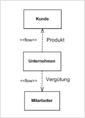
The language unit information flows , which was newly introduced in UML2, provides model elements to improve this situation. It offers the model elements information unit and information flow with which a modeler can record information flows in a system at a high level of abstraction.
Information flows can connect a large number of other model elements of UML2, in particular classes , use cases , specification specifications , actors , interfaces , ports and a few more.
UML2 does not specify a diagram type for information flows. The graphical notation for information flows and information units can appear in all structure diagrams.
Interactions
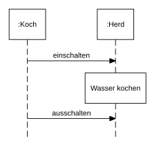
The behavior of a modeled system can be specified in UML2 in different ways. One of them is the modeling of interactions . An interaction is the specification of a behavior that is best described by the exchange of messages between independent objects. The language unit provides the appropriate model elements for this.
Anyone who models interactions assumes that the modeled system consists of a network of objects that exchange messages with one another. If an object sends a message to another object, two event occurrences can be identified: first, the occurrence of a message event when the message is sent by the first object and, secondly, a message event when the message arrives at the second object. Other events occur when an action or other behavior begins or ends in the context of an object. A trace describes a sequence of such events. Interactions now specify behavior as two sets of traces, a set of valid and a set of invalid traces.
This means more precisely what we mean when we speak of interactions: the meaning ( semantics ) of an interaction is given by sets of traces. However , interactions are modeled as sets of lifelines on which actions and other behaviors take place and between which messages are exchanged.
Interactions are modeled graphically in communication diagrams , in sequence diagrams or in timing diagrams .
Classes
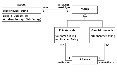
The language unit classes comprises the actual core of the modeling language. In particular, it defines what is understood by a class in UML2 and what relationships are possible between classes. The basic principles of UML2 are defined in this language unit. The Element metaclass is the root element for all other model elements. Each element can have other elements, including any number of comments , which in turn can also comment on several other elements. Relationships can be defined between elements . Elements can be named and in this case belong to a namespace . Furthermore, certain elements can have a type . They are then called typed elements . A multiplicity with a lower and an upper limit can be assigned to an element .
This language unit contains four sub-packages. The Kernel sub-package comprises central modeling elements that are reused from the UML 2.0 Infrastructure . These include the class , the occurrence specification , the namespace , the package , the attribute , the association , the dependency relationship , the package import , the package merging and the generalization . The second sub-package, AssociationClasses , contains the definition of association classes . Interfaces , the third sub-package, provides the definition of interfaces . Finally, the subpackage PowerTypes declares model elements for the so-called PowerTypes .
Elements from this language unit are mostly represented in class diagrams , object diagrams and package diagrams .
Components
Components are modular parts of a system that are structured in such a way that they can be replaced by another, equivalent component in their environment. In software development , the concept of software components is used in particular to divide a software system into modular parts. The language unit components of UML2 provides constructs to model systems that are built up from components.
The most important element is the component that delimits an internal structure from the outside. The specification of a component primarily declares the edge that is visible from the outside and thus defines a black box view of the component. A number of offered and required interfaces and possibly a number of ports are visible .
The language unit further comprises the delegation and the composition connector . The delegation connector connects ports on the shell of a component with elements inside the component. The composition connector connects offered interfaces of one component with required interfaces of another component.
The elements of this language unit are mostly shown in component diagrams, but sometimes also in class diagrams or distribution diagrams.
Compositional structures
The language unit Composition Structures enriches UML2 with a new approach for modeling the internal structure of a composite whole. The “whole” is modeled as an encapsulated classifier ; this language unit provides the parts for the “parts” . Parts can be connected to one another by connectors . The encapsulated classifier stands for a system with a clear distinction between inside and outside, the internal structure of which is specified with the help of parts and connectors. So that the boundary between inside and outside is at least partially permeable, the encapsulated classifier on the shell can have a number of entry and exit points, so-called ports .
Elements from this language unit are mostly represented in composition structure diagrams.
Models
The language unit models comprises only one model element: the model .
Profiles
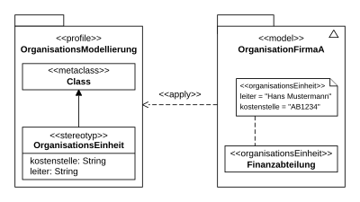
With the language unit Profiles, UML2 provides a lightweight extension mechanism with which it can be adapted to specific areas of application. The mechanism is described as lightweight because it leaves the UML2 metamodel unchanged, which is often a decisive advantage, because tools available on the market for creating and maintaining UML2 models can often only handle models based on the standardized UML2 metamodel.
UML2 includes various options for modeling the structure and behavior of a system in its language units, but must remain on a generic level. For example, it uses the generic terms activity or artifact and does not know the specific term business process from business modeling or Enterprise JavaBeans from the Java platform. If these terms are required in the modeling, they must be added to UML2 using the extension mechanism of the profiles. Special notations, for example a more realistic drawing instead of the stick figure representing an actor , can also be added to UML2 using the profiles. Profiles can also close gaps in the semantic definition of UML2 that were intentionally left open for specific areas of application (English semantic variation points ). Finally, profiles can define constraints to restrict the way in which a UML2 element is used.
With the help of the extension mechanism of the profiles, however, the metamodel of UML2 cannot be adapted at will. For example, no elements can be removed from the UML2 metamodel, no restrictions can be lifted and no real new metaclasses can be declared, only extensions ( stereotypes ) of existing metaclasses.
The language unit first defines the concept of a profile . A profile is a collection of stereotypes and defines the actual extension. A profile is a packet and other packets applied , whereby the extension that defines the profile applies to the corresponding package.
UML2 has known a special diagram type for profiles since UML 2.2. The graphical notations for elements from this language unit appear both in package diagrams and in class diagrams .
Stencils
The language unit templates (English templates ) comprises model elements for the parameterization of classifiers , classes and packages .
Distributions
The language unit distributions (English deployments ) is geared towards a very specific area of application, namely the distribution of executable software in a network . UML2 describes a unit that can be installed in this way as an artifact and assumes that it is installed on nodes . Nodes can be either devices or execution environments . A distribution relationship , that is, a special dependency relationship , models that an artifact is installed on a node.
Elements from this language unit are usually represented in distribution diagrams.
State machines

The language unit state machines (English state machines ) comprises model elements that are used for the modeling of state machines.
UML2 uses state machines primarily to specify the behavior of a system. For example, a state machine can model the behavior of the instances of an active class . In addition, state machines can also be used to specify the permitted use of an interface or a port . The state machine models, for example, the order in which operations of an interface may be called. In the first case one speaks of a behavioral state machine , in the second of a protocol state machine .
State machines are represented graphically in state diagrams. In UML, these are a variant of the classic Statecharts .
Diagrams
Chart types
The diagrams in UML can be divided into two main groups: structure diagrams and behavior diagrams.

UML2.3 knows seven structure diagrams:
- the class diagram ,
- the composition structure diagram (also: assembly diagram),
- the component diagram ,
- the distribution diagram ,
- the object diagram ,
- the package diagram and
- the profile diagram .
There are also seven behavioral diagrams:
- the activity diagram ,
- the use case diagram (also called use case diagram),
- the interaction overview diagram ,
- the communication diagram ,
- the sequence diagram ,
- the timing diagram and
- the state diagram .
The boundaries between the fourteen diagram types are less sharp than this classification suggests. UML2 does not prohibit a diagram from containing graphic elements that actually belong to different diagram types. It is even conceivable that elements from a structure diagram and from a behavior diagram are shown on the same diagram, if a particularly relevant statement is made about a model.
In other respects UML2 deals with diagrams much more formally than UML 1.4. UML2 has redefined an exchange format for diagrams under the name UML 2.0 Diagram Interchange , so that various tools with which models based on UML2 are created can exchange and reuse the diagrams. In UML 1.x this was only possible for the repository models "behind" the diagrams, but not for the actual diagrams.
Create diagrams
UML2 diagrams can be created in a number of ways. When the notation of UML 2 is used as a common language in order in an analysis Team designs of analytical models on the whiteboard ( whiteboard ) noted rich pencils and paper as a tool. Often, however, UML2 diagrams are created with the help of special programs (UML tools) that can be divided into two classes.
Programs in the first group help to draw UML2 diagrams without having to store the model elements that correspond to the graphic elements on the diagrams in a repository. This group includes all programs for creating drawings.
The second group consists of programs that support the creation of models and drawing of diagrams of UML2.
Exchange of models and diagrams
So that models can be transferred from one tool to another, the Object Management Group defines a standardized exchange format that is also used for UML models. The format is based on the markup language XML and is called XML Metadata Interchange (XMI). The basis for interchangeability is the MOF , on whose concept both languages, XMI and UML, are based.
For UML versions 1.x, the format did not provide for the possibility of exchanging diagrams in a standardized format, which was perceived by many users as a major gap. In parallel to the development of UML2, OMG has therefore also revised the standardized XMI exchange format. Among other things, the gap described was closed by expanding the specification under the name UML 2.0 Diagram Interchange to include a format for the exchange of diagrams.
An exchange with other modeling languages is also possible by means of model-to-model transformation. The OMG has defined the MOF QVT standard for this purpose. In contrast to a pure exchange format, a transformation can also contain its own semantics. For example, it can be determined how a class model is to be mapped onto an ER model. The flexibility that comes with this is particularly useful when exchanging tools, as different providers practically always have individual variants of the UML metamodel.
See also
- Related OMG initiatives and language recommendations:
- Other modeling methods and language families:
- EXPRESS (see STEP )
- Fundamental Modeling Concepts (FMC)
- IDEF
literature
- Heide Balzert : UML 2 in 5 days . W3L, 2005, ISBN 3-937137-61-0
- H. Baumann, P. Grässle, Ph. Baumann, UML 2 project-oriented . Galileo Computing, 2007, ISBN 978-3-8362-1014-0
- Grady Booch , James Rumbaugh , Ivar Jacobson : The UML User Guide. Current version 2.0 . Addison-Wesley, 2006, ISBN 978-3-8273-2570-9 (translated from the American).
- M. Born, E. Holz, O. Kath: Software development with UML 2 . Addison-Wesley , 2004, ISBN 3-8273-2086-0
- B. Bruges, AH Dutoit: Object-oriented software technology with UML, design patterns and Java . Pearson Studies , 2004, ISBN 3-8273-7082-5
- M. Fowler , Scott Kendall: UML focused . Addison-Wesley , 2000, ISBN 3-8273-1617-0
- M. Fowler : UML Distilled . 3. Edition. Addison-Wesley , 2003, ISBN 0-321-19368-7
- M. Hitz, G. Kappel, E. Kapsammer, W. Retschitzegger: UML @ Work . dpunkt.verlag , 2005, ISBN 3-89864-261-5
- B. Kahlbrandt: Software engineering with the Unified Modeling Language . Springer, 2001, ISBN 3-540-41600-5
- Christoph Kecher, Alexander Salvanos: UML 2.5 - The comprehensive manual . Rheinwerk Computing, 2015, ISBN 978-3-8362-297-77
- Bernd Oestereich , Axel Scheithauer: Analysis and design with UML 2.5: Object-oriented software development . R. Oldenbourg Verlag , 2013, ISBN 978-3-486-72140-9
- Dan Pilone: UML - in a nutshell . O'Reilly , ISBN 3-89721-263-3
- Bernhard Rumpe: Modeling with UML . 2nd Edition. Springer, Berlin, 2011. ISBN 978-3-642-22412-6
- Chris Rupp , Stefan Queins, Barbara Zengler: UML 2 crystal clear. Practical knowledge for UML modeling . Hanser Verlag , 2007, ISBN 978-3-446-41118-0
- Sinan Si Alhir: Learning UML . O'Reilly Verlag , ISBN 0-596-00344-7
- H. Störrle: UML 2 for students . Pearson Studies Germany, 2005, ISBN 3-8273-7143-0
- H. Störrle: Use UML 2 successfully . Addison-Wesley , 2005, ISBN 3-8273-2268-5
- M. Winter: Methodical object-oriented software development . dpunkt.verlag , 2005, ISBN 978-3-89864-273-6
To certification
- Tim Weilkiens , B. Oestereich: UML2 certification . dpunkt.verlag , 2004, ISBN 3-89864-294-1
- Tim Weilkiens , B. Oestereich: UML2 certification: Intermediate level . dpunkt.verlag , 2005, ISBN 3-89864-312-3
- Tim Weilkiens , B. Oestereich: UML 2.0 certification preparation. Fundamental, Intermediate and Advanced . dpunkt.verlag , 2006, ISBN 3-89864-424-3
Coupled with procedural models
- Bernhard Rumpe: Agile modeling with UML: code generation, test cases, refactoring . 2nd Edition. Springer, Berlin, June 2012. ISBN 978-3-642-22429-4
- W. Zuser, T. Grechenig, M. Köhle: Software engineering with UML and the Unified Process . Pearson Studies, 2004, ISBN 3-8273-7090-6
Web links
Specifications for the UML2
- OMG Unified Modeling Language TM (OMG UML), Version 2.5 (English; PDF)
- UML 2.4.1 Infrastructure Specification (English; PDF)
- UML 2.4.1 Superstructure Specification (English; PDF)
- UML specification in all versions
Further
- Overview of UML tools
- MOF 2.0 Core Specification (English; PDF)
- MOF 1.4 Specification (English; PDF)
- OMG website on UML (English)
- The modern software development process with UML . Online book on UML (German)
- Death by UML Fever . - A critical article on UML, published in the Communications of the ACM
Individual evidence
- ↑ omg.org: OMG Formal Versions of UML
-
↑ Part 1 of the specification of the language (infrastructure)
Grady Booch: The unified modeling language user guide. Boston 1998, p. 15 - ↑ OMG website ( Memento from August 7, 2011 in the Internet Archive )
- ↑ UML 2.0 OCL
- ↑ UML 2.0 Infrastructure ( page no longer available , search in web archives ) (PDF)
- ↑ omg.org/spec/UML/2.2
