Battery switch
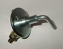
A battery switch or main battery switch is a switch that is mainly used in commercial vehicles, where it has the function of disconnecting one or more batteries from the connected vehicle electrical system . A simple battery switch cannot take over the function of an emergency stop switch for the vehicle engine, since the actuation of the switch is ineffective when the engine is running. The main battery switch is common on many military vehicles. The right key is called nato bone in Bundeswehr jargon .
Basics
In vehicles , the electrical system is usually switched in such a way that most consumers are de-energized after removing the ignition key . The lines to the starter and to the ignition switch or to the fuse box are still live. If one of these lines is damaged, a cable fire may occur, as these main lines are also not protected. In addition, a permanent short circuit in the non-fused part of the vehicle electrical system, for example in the positive lead to the starter, can destroy the battery. To prevent this, hand-operated battery switches are installed. These switches are suitable for large currents , but only for low nominal voltages (12 to 48 volts ). They are switched to the main battery lines to interrupt the power supply. For this purpose, the main battery switch is installed in the vehicle as close as possible to the battery so that a (vehicle) operator can operate it if necessary. Battery switches are available with one or more switching contacts. In addition to the main contacts, these switches can be equipped with auxiliary contacts.
A distinction is made between battery switches:
According to the type of operation:
- Rotary switch
- Pressure switch
- Switch with removable lever. In certain uses, such as forklifts , switches with a removable lever are required by law. They prevent the vehicle from being started by unauthorized persons. At the same time, they serve as protection against theft.
According to the switching capacity:
- Disconnector
- Load switch
Isolating switches may only be switched empty, i.e. without any significant current flow. Load switches are allowed to switch the rated currents for which they are designed. Normal motor vehicle switches are not suitable for use as battery switches because they have insufficient contact load capacity. This must be taken into account when selecting a battery switch.
Layout and function
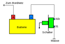
The battery switch is usually connected as a single-pole normally open contact in the negative return line between ground and negative pole of the battery. There are switches with an insulated housing and switches with a metal housing. Switches with a metal housing have only one insulated connection contact and are connected to the ground with the second connection (housing) during installation . When installing a battery switch in the negative return line, the ground strap coming from the battery must be insulated, otherwise the battery switch will be ineffective (see ground short circuit ). Switches with an insulated housing have two connection terminals and can also be connected to the positive line, but this type of connection is not common. Two-pole battery switches are also available for vehicles with two batteries.
The manually operated battery switch is only effective when the combustion engine is at a standstill, when the alternator is not emitting any voltage. If the switch is switched off while the system is in operation, there will be an excessive voltage increase in three-phase alternators due to the remanence of the alternator. This can destroy the alternator diodes . Therefore, the manually operated battery switch may only be operated when the engine is at a standstill. In addition, the internal combustion engine continues to run despite the switch being activated, as it is supplied with electrical voltage from the alternator . This means that the battery switch cannot perform an emergency stop function in internal combustion engines. If the battery switch is switched off when the internal combustion engine is at a standstill, this engine can no longer be started because the voltage supply for the entire on- board electrical system is interrupted. Due to the sensitive on- board electronics , it is often necessary to connect a resistor via a contact of the switch, which serves as a so-called protective circuit and dampens voltage peaks that occur .
In commercial vehicles with a combustion engine and two or more batteries or in vehicles with 24-volt starter systems (for example in heavy buses), electromagnetic switches are used instead of the manually operated battery switch. For this purpose, special relays with several load contacts are installed near the batteries. The relays are operated from the driver's seat using the travel switch. The switch is locked by means of a control line via an NC contact of the relay.
Areas of application
Battery switches are used in the commercial vehicle sector, in campers or mobile homes , in government vehicles, the military , racing vehicles, agricultural vehicles and boats.
The battery can be switched off using the battery switch
- in order to prevent discharge due to unwanted power consumption of the starter battery during long periods of idle time due to standby currents such as radio receivers or leakage currents in the case of inadequate electrical equipment
- to secure the vehicle against unauthorized use
- in case of emergancy
A battery switch can not prevent cable fires due to missing line fuses in the event of a short circuit in the vehicle electrical system .
Use as a battery main switch
For use as a battery master switch, load switches should primarily be used. If disconnectors are used for this application, it must be ensured that the switch is never switched under load. A simple option is to attach a notice in the immediate vicinity of the switch. Locking the switch via a battery relay is much safer. To do this, you need a battery switch with an auxiliary contact, via which the coil of the battery relay is switched off or on. The switching contact of the battery relay is switched to the positive line to the on-board network. When the battery switch is switched on, the negative pole of the battery is first connected to ground, the battery relay is actuated via the now closed auxiliary contact and switches the positive pole through to the on-board network. When the battery switch is switched off, the auxiliary contact opens and the battery relay opens the relay contact, which in turn interrupts the positive lead and then the battery switch opens the connection between the negative battery terminal and ground.
Use as an emergency switch
With certain sports vehicles, for example, the use of battery switches is prescribed as a safety measure in order to enable both the external helper and the driver to switch off the vehicle completely (risk of short circuit and fire in the event of an accident). These switches, often referred to in brochures as battery isolating switches, are battery switches that have two auxiliary contacts in addition to the main contact. One contact interrupts the ignition when actuated, possibly via a relay, the other interrupts the fuel supply to the combustion engine. These switches are pressure switches equipped with a so-called mushroom head, which can then take on the function of an emergency stop switch . Another variant for an emergency switch in racing vehicles is the pull cord switch . This is a battery switch with a removable switch lever that is opened using a rip cord in the event of an accident in order to bring the engine to a standstill.
Other use in vehicles
Switchable parallel operation of batteries
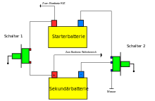
In commercial vehicles , such as mobile homes , there are usually two, sometimes even more, batteries that perform different tasks. So that the actual starter battery in these vehicles cannot be discharged via the other circuits (interior lighting, refrigerator, etc.) when the vehicle is stationary, the batteries are easily separated from one another using the battery switch.
If batteries are operated in parallel for a longer period of time and are not recharged, they will discharge each other while standing. To prevent this, the batteries are only electrically connected to one another via the battery switch when required.
Battery switches can also be used in private cars if you B. wants to operate powerful hi-fi amplifiers while standing. Only hand-operated switches that are dimensioned as load switches should be used. These switches must have an insulated housing so that there are no short circuits with the ground. With a battery switch connected in this way, you can connect the positive poles of the built-in batteries to one another or disconnect them if necessary .
Separation of parallel operation
The parallel operation of the battery is interrupted via the battery switch:
- to prevent unwanted power consumption of the starter battery when the vehicle is parked,
- to prevent the starter battery from discharging through the rest of the on-board network,
- in order to prevent mutual discharge of the batteries when the vehicle is parked,
- this ensures that the starter battery is given priority.
Installation and interconnection
The switch should be installed within reach of the driver, if possible in the dashboard , so that the driver can reach it at any time while driving. To prevent the switch contacts from scorching after a short time, a load switch must be installed. The nominal current information can be seen in the manufacturer's documents.
The cables to the switch should be laid in such a way that they cannot be damaged, and they must also have a large cross-section (at least 6 mm²). Immediately behind the two batteries, the cables must each be protected with a fuse that corresponds to the cable cross-section in order to prevent a cable fire.
Monitoring of the on-board network and operation
It must be ensured that the switch is switched on again with the engine running so that the other batteries are also charged. The switch should only be switched on when the alternator has enough charging energy, otherwise the batteries will not be charged enough. This is particularly critical when a large number of consumers are switched on in the primary on-board network and the alternator generates just enough power for the primary on-board network. Since in this case the amount of electricity is insufficient to charge all the batteries, the batteries are only partially charged. As a result, in extreme cases, the starter battery cannot be charged enough to defy a possible cold start on the other day. Before operating the starter, the battery isolator switch should be opened so that the starter battery is available with its full capacity for the starting process. In addition, this measure is intended to prevent a reverse current from flowing from the secondary battery via the battery switch. With parallel operation, an additional charge control should always be carried out using an ammeter and a voltmeter so that the driver can disconnect the secondary network if necessary.
The constant actuation of the switch and the permanent monitoring of the operating conditions can be a considerable additional burden for a driver. A much more convenient variant are so-called battery disconnect relays , which automatically disconnect or connect the vehicle electrical system. As these automatic functions cannot be performed by manually operated switches, battery switches are only of limited use. For this reason, isolating relays are mainly used for battery isolation. Hand-operated battery switches are usually only used as so-called battery main switches. However, the installation of an isolating relay is more expensive and complex, so the use of the battery switch is often an inexpensive and simple variant for the functions described above, especially when currents up to a maximum of 40 amperes have to be switched.
Use outside of vehicles
In principle, manually operated load switches are also suitable for other applications in order to activate a circuit in the range of 100 amps and more from a 12 volt to 48 volt supply, for example in the camping and caravan sector. But these switches are also used in certain systems, for example power generators , solar systems , magnetic coils or in smaller electroplating systems.
safety instructions
- Although the circuit appears very trivial, the possible current intensities require considerable knowledge in the dimensioning of the lines, their protection and precise expertise in the production of gas-tight line connections.
- Working on the on-board electrical system requires specialist knowledge. In the event of improper handling or incorrect installation, short circuits can occur, which can injure the fitter as well as serious damage to the vehicle, e.g. cable fire.
Laws and other regulations
- DIN EN 60617-2: 1996 Graphic symbols for circuit diagrams - Part 2: Symbol elements, labels and other circuit symbols for general applications (IEC 60617-2: 1996)
- EN 61058-1: 2002 + A2: 2008 Equipment switches - Part 1: General requirements (IEC 61058-1: 2000, modified + A1: 2001 + A2: 2007)
- BGV D29 (old: VBG 12) vehicles, professional association guideline
See also
Individual evidence
- ↑ a b c d e Robert Bosch GmbH (Ed.): Autoelectrics Autoelectronics. 5th completely revised and expanded edition. Vieweg & Sohn Verlag, Wiesbaden 2007, ISBN 978-3-528-23872-8 .
- ↑ a b c Limora (Ed.): Instructions for battery disconnectors . Limora spare parts for classic British vehicles, company brochure, Buchholz.
- ↑ Ulrich Cimolino, Jörg Heck: Technical assistance in case of truck accidents. Ecomed Verlagsgesellschaft, Landsberg 2003, ISBN 3-609-68661-8 , pp. 116-118.
- ↑ Friedrich Borrosch: motorhomes. The great freedom, 2nd edition, epubli Verlag, Berlin 2014, ISBN 978-3-8442-8422-5 .
- ↑ a b Rudolf Hüppen, Dieter Korp: Auto electrics all types. Motorbuchverlag, Stuttgart, 1968, ISBN 3-87943-059-4 .
- ↑ a b Jürgen Kasedorf, Richard Koch: Service Primer for automotive electrical. 14th revised edition, Vogel Buchverlag, 2001, ISBN 3-8023-1881-1 .
- ^ BOSCH: Technical instruction on electrical starting systems. Robert Bosch GmbH Stuttgart, Automotive Equipment Division, 1972, VDT-UBE 501/1.
- ↑ a b c Schlemmer Electronics: Electromechanical Components . Online ( Memento of August 18, 2016 in the Internet Archive ) (accessed on August 18, 2016).
- ↑ ETA Elektrotechnische Apparate GmbH (Ed.): User manual for battery disconnector BMS01 . Altdorf 2016, pp. 6-7.
- ↑ a b Jens Feddern: Theory and practice of on- board electrics . 5th revised edition, Delius Klasing Verlag, Bielefeld 2009, ISBN 978-3-7688-0913-9 , pp. 109-115.
- ^ BOSCH: Technical briefing on generators. Robert Bosch GmbH, Stuttgart, Automotive Equipment Division, 1972, VDT-UBE 301/1 DE (1.80).
- ↑ a b Dethleffs GmbH & Co. KG (Ed.): Operating Instructions Motor Caravan . Isny 2015, pp. 141–142.
- ^ BOSCH: Technical briefing on batteries. Robert Bosch GmbH, Stuttgart, Automotive Equipment Division, 1972, VDT-UBE 410/1.
- ↑ Ulrich Cimolino, Holger de Vries: Emergency vehicles for fire and rescue services . 1st edition, Verlagsgruppe Hüthing Jehle Rehm GmbH, Landsberg 2005, ISBN 3-609-68665-0 , pp. 170-171.
- ↑ Andreas Weingand: ABC around the mobile home. Mobile home technology explained in an understandable way, Norderstedt 2016, ISBN 978-3-7322-8621-8 , pp. 212–213.
- ↑ Infineon and SCHWEIZER present a demonstrator of a powerful battery switch at the “Electronics in the vehicle” congress . Press release at the "Electronics in Vehicles" congress, October 16, 2013.
- ↑ Gabor Ludányi, Jens giant mountain: battery backup and battery switches in a UPS system. EFEN GmbH, Eltville.


