
fan

A fan (from the Latin ventilare 'to generate wind' , ' to fan cooling') is an externally driven flow machine, i.e. a working machine that conveys a gaseous medium . For this purpose, it has an impeller with an axial or radial flow , which usually rotates in a housing. A pressure ratio between 1 and 1.3 is achieved between the suction and pressure side (small fans up to 1.03). Turbo machines that achieve a pressure ratio greater than 1.3 are called compressors . According to the standard, the terms blower and fan should no longer be used in technical parlance .
Fans set max. 25 kJ / (kg • K) um, which at an assumed density of 1.2 kg / m³ (air) corresponds to 30,000 Pa, hence the factor 1.3 according to DIN 5801 and 13349.
Designs
Axial fan


Axial fans are the most common design. The axis of rotation of the axial impeller runs parallel (axially) to the air flow. The air is moved by the axial impeller similar to an airplane or ship propeller. Axial fans achieve a high throughput with small dimensions. The achievable pressure ratio is smaller than with centrifugal fans.
The design without a housing is common for table and ceiling fans (fans). Axial fans with housing and inner drive motor have the disadvantage of the hub dead water behind the impeller hub , but which is obtained by a suitable diffuser can be largely avoided (inner diffuser). Since the air exits behind the axial impeller with a swirling effect, the static pressure is increased by fixed installations (guide wheel) by converting the dynamic energy contained in the swirl ( angular momentum ) into potential energy (static pressure). In order to minimize the pressure loss from the axial fan, larger fans have external diffusers.
Diagonal fan
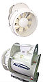
Another version of the flow machines is the so-called diagonal fan, in which the housing and the fan blades are conically shaped (the radius increases towards the pressure side) so that the air does not exit axially, but diagonally. Diagonal fans have a greater air flow rate and build up a higher pressure with the same power and size, so they can be operated at a lower speed with the same effect and are therefore quieter.
Both versions have a so-called hub dead water, which is located behind the motor located in the middle of the device: there is hardly any air movement there. For this reason, axial fans have already been developed which contain the motor in a surrounding housing and in which only the bearing is located in the middle. However, due to the unusual design of the motor, this version is rather rare and also more expensive than comparable axial fans. Balancing is also laborious because of the large, external circumferential mass of the drive. Particularly compact fans are usually driven directly by an external rotor motor.
Radial / centrifugal fan

Centrifugal fans are used wherever a greater pressure increase with the same amount of air is required compared to axial fans. The air is drawn in axially (parallel to the drive axis) of the radial fan and deflected by 90 ° by the rotation of the radial impeller and blown out radially. A distinction is made between impellers with backward-curved blades (at high pressures and degrees of efficiency), straight blades (for special purposes such as particle-laden flows to reduce buildup) and forward-curved blades (for low pressures and degrees of efficiency, see also the section on cross-flow fans ). There are single-sided and double-sided centrifugal fans with and without a housing. In the case of the version with a helical housing, this is oriented so that the remaining tangential component of the flow is directed towards the outlet. The air is usually blown out at a flange or a pipe socket. In order to minimize the pressure losses due to the high exit speed from the centrifugal fan, attention must be paid to the appropriate design of the downstream duct (if necessary with a diffuser). In the version without a spiral housing, the air is blown radially out of the radial impeller and blown out into the open through a suitable housing design, as with roof fans. Such fans or those that contain further compressor stages (for example vacuum cleaner blowers) often have guide vanes on the outlet circumference in order to use the tangential flow component.
Tangential or cross flow fans
At first glance, these look like wide or elongated centrifugal fans, but the functional principle is fundamentally different. They have blades pointing forward, i.e. in the direction of travel. With tangential fans, the air is fed through the fan wheel twice: it is drawn in tangentially over a large area, approximately over half the surface of the fan wheel, passed through the inside of the wheel and also released again tangentially. The wheel transports a small proportion of air outside. The air then usually exits through a narrow gap the width of the fan wheel on the opposite side. The drive motor is usually located in or at the end of the impeller; Correspondingly small motors can also be accommodated inside the fan wheel, which also improves their cooling.
Tangential fans can emit large amounts of air evenly over a wide outlet area and are used in air conditioning units , night storage heaters and fan heaters . Since they have a sufficient air flow rate even at low speeds, the tangential fans, which are mostly driven by shaded pole motors , are very quiet during operation and are therefore well suited for cooling, for example, overhead projectors . They are also preferred in column or tower fans. This type of fan is not suitable for building up higher pressures.
Technical key figures
The pressure increase achieved changes depending on the volume flow. In order to be able to compare fans with each other, key figures can be used. These metrics are
- Printing number
- Delivery number or flow rate
- Run number
- Specific speed
- Diameter number
- Efficiency
- specific sound power level
- Performance figure for turbo machines
The fans can be classified in the Cordier diagram .
Non-binding reference values
The table contains the values of fans with the best technology available on the market at the time this regulation was adopted. These reference values may not always be achieved in all applications or for the entire range of services covered by this regulation:
| Fan type | Measurement category (A – D) |
Efficiency category (static or total efficiency) |
Degree of efficiency (N) |
| Axial fan | A, C B, D |
static total |
65 75 |
| Centrifugal fan with forward curved blades and centrifugal fan with radial blades |
A, C B, D |
static total |
62 65 |
| Centrifugal fan with backward curved blades without casing | A, C | static | 70 |
| Centrifugal fan with backward curved blades with casing | A, C B, D |
static total |
72 75 |
| Diagonal fan | A, C B, D |
static total |
61 65 |
| Tangential fan | B, D | total | 32 |
Definition of terms:
- "Measurement category" refers to a test, measurement or operational arrangement that defines the inlet and outlet conditions of the tested fan (installation situations in accordance with ISO 5801)
- "Measurement category A" refers to an arrangement in which measurements are taken on the fan with free inlet and outlet conditions
- "Measurement category B" refers to an arrangement in which measurements are taken on the fan with a free inlet and with a pipe mounted on the outlet
- "Measurement Category C" refers to an arrangement in which measurements are taken on the fan with a pipe mounted on the inlet and with free outlet conditions
- "Measurement category D" refers to an arrangement in which measurements are taken on the fan with a pipe mounted on the inlet and one on the outlet
- “Efficiency category” refers to the output energy form of the fan gas used to determine the energy efficiency - ie the static efficiency or the total efficiency - of the fan, whereby
- a) the "static fan pressure" (p sf ) was used to determine the fan gas output in the efficiency equation for the static efficiency of the fan and
- b) the "total pressure of the fan" (p f ) was used to determine the fan gas output in the efficiency equation for the total efficiency of the fan
- "Degree of efficiency" denotes a parameter in the calculation of the target energy efficiency of a fan with a certain electrical input power at the energy efficiency optimum (represented as parameter "N" in the calculation of the energy efficiency of the fan)
- “Target energy efficiency” η The goal is the minimum energy efficiency that a fan must achieve in order to meet the requirements; it is based on its electrical input power at the energy efficiency optimum, where η target is the output value from the corresponding equation in Annex II, Section 3, using the relevant integer N of the degree of efficiency (Annex I, Section 2, Tables 1 and 2) and that expressed in kW electrical input power P e (d) of the fan at its energy efficiency optimum in the relevant energy efficiency formula
- "Overall efficiency" means either the "static efficiency" or the "total efficiency" depending on the case.
Requirements of the ErP Ecodesign Directive
The decision criterion for the energy efficiency of fans is the system efficiency, which is made up of the efficiency of the fan, the motor and the control electronics.
The requirements were raised again in a second stage on January 1, 2015 (see table).
| Fan category | Measurement category (A – D) |
Fan pressure | Power range > 0.125 kW efficiency |
Power range > 10 kW efficiency |
Power range > 500 kW efficiency |
| Axial fan | A, C B, D |
static total |
28 46 |
40 58 |
43 61 |
| Centrifugal fan with forward curved blades and centrifugal fan with radial blades |
A, C B, D |
static total |
32 37 |
44 49 |
47 52 |
| Centrifugal fan with backward curved blades without casing | A, C | static | 42 | 62 | 66 |
| Centrifugal fan with backward curved blades with casing | A, C B, D |
static total |
41 44 |
61 64 |
65 68 |
| Diagonal fan | A, C B, D |
static total |
30 42 |
50 62 |
54 66 |
| Tangential fan | B, D | total | 16 | 21st | 21st |
The system efficiency
The system efficiency of the fan unit consists of the efficiency of the fan ( ), the motor ( ), the drive ( ) and the control ( ) as follows:


The system efficiency differs greatly depending on the type of fan and the technology used. For example, the efficiency of axial fans with an input power of up to 10 kW is on average between 25 and 45%, and for freewheels with backward-curved blades up to 10 kW input power, between 35 and 60%. The system efficiency improves with increasing volume flow and power consumption of the motor, since the motor efficiency (75 to 95%) and the drive efficiency (90 to 95% for V-belts up to 97% for flat belts) improve significantly. The fan efficiency increases only moderately. Since most air conditioning systems are operated variably, either a frequency converter with an efficiency of 95 to 97% or a controller integrated in the motor is used for regulation.
Product information requirements
Conditions:
No. 1. The information on fans mentioned in No. 2 points 1 to 14 must be visibly made available as follows:
- a) in the technical documentation for fans
- b) on freely accessible websites of the fan manufacturers
No. 2. The following must be stated:
- Total efficiency (η) rounded to one decimal place
- Measurement category (A – D) used to determine the energy efficiency
- Efficiency category (static efficiency or total efficiency)
- Efficiency at the energy efficiency optimum
- whether the calculation of fan efficiency is based on the assumption that speed control is used; if so, whether it is integrated into the fan or whether it must be installed with it
- Year of manufacture
- Name or trademark , official registration number and place of business of the manufacturer
- Model number of the product
- Nominal motor input power (s) (kW), mass or volume flow (flows) and pressure (pressures) at the energy efficiency optimum
- Revolutions per minute at optimum energy efficiency
- "Specific ratio"
- Information relevant to facilitating dismantling, recycling or disposal after final decommissioning
- Relevant information on the installation, operation and maintenance of the fan for minimizing the environmental impact and ensuring an optimal service life
- Description of other items used to determine the energy efficiency of fans, such as pipes , which are not described in the measurement category and are not supplied with the fan.
The information in the technical documents is to be provided in the order according to No. 2 points 1 to 14. It is not necessary to repeat the exact formulations used in the list. The information can also be provided in the form of graphics , diagrams and symbols instead of text .
The information mentioned in No. 2 points 1, 2, 3, 4 and 5 must be given permanently on or near the rating plate; With regard to number 2 point 5, the one of the following formulations must be used that applies:
- "A speed control must be installed with this fan."
- "A speed control is integrated in this fan."
In the operating instructions, the manufacturers provide information on special safety precautions to be taken when assembling , installing or maintaining fans. If a speed control has to be installed with the fan in accordance with No. 2 point 5 of the requirements for the product information, the manufacturers provide details of the properties of the speed control to ensure optimal operation after installation.
application
Most fans convey air and belong to the specialist field of air technology or ventilation . When restricted to this medium: air , the following areas of application arise:
-
Air conditioning :
- The temperature and humidity of the room air is controlled by air circulation.
- Cooling : The waste heat from a component or unit is absorbed and transported away by the air flowing past.
- Drying : The moisture from fabrics is removed by the flow of dry air.
- Ventilation: Bad air or possibly contaminated, poisonous gases should be removed from a room and sucked off. In some cases, breathing air must be guaranteed (for example mining - tunnel ventilation ).
- Explosion protection : Blowing away flammable gases (for example propane, which is heavier than air) prevents dangerous concentrations.
- Air supply : Technical furnaces usually have a fan that transports the combustion air to the burners or directly into the combustion chamber . For example, the steam locomotive of Marc Seguin was a tender equipped its large fans for a supply of the firebox with the necessary fresh air with oxygen for the combustion of coal ensured.
- Transport : Air can be used to transport suspended substances such as grain or cement inexpensively. The pneumatic tube also works with air.
- Musical instrument making : Organs are operated with radial fans .
In the PC area
The waste heat from the power supply unit is - with a few exceptions ("whisper mode " due to fanless operation ) - conveyed to the outside by a fan and at the same time causes a permanent flow of air in the housing itself. Subliminal constant noise pollution at the workplace is therefore unavoidable.
With increasing processor performance, "active cooling" (initially only for the CPU ; from i486 ) became necessary, i.e. a heat sink with a fan so that the tightly packed circuits inside the chip do not get too hot, which can lead to premature failure. This measure was later extended to the graphics processors of graphics cards and the chipsets of the motherboards , as well as to the hard disks, especially if there are several at the same time. Due to the narrow and flat housings, especially for servers (“pizza box” or “pizza rack ”), additional fans were required, as the memory modules and the voltage divider capacitors also require special heat dissipation.
To operate a fan requires a supply voltage, typically 12 V. With a lower voltage, however, it also provides less cooling capacity. If the voltage falls below a certain, normally not precisely defined, voltage value, the rotor stops. A third cable supplies a so-called speed signal for feedback of the speed and thus the functionality. It changes its level one or more times per revolution . Some fans have a fourth connection via which the speed can be controlled (for example by pulse width modulation (PWM)).
photos
- Typical designs and applications

Ceiling fan, rotating slowly
Axial fan with hybrid drive (compressed air / three-phase current)

Miniature axial fans, ventilation of devices and enclosures

2.5 meter large axial fan for tunnel ventilation

Hand fan with flexible blades
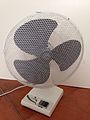
Room fan
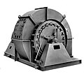
Centrifugal fan as ship boiler fan

Porsche 911 engine with axial fan

Building ventilation fan

Centrifugal fan (centrifugal fan) for an organ

Graphic symbol for a fan according to DIN EN 12792

Axial fan symbol according to DIN EN 12792


History of fan production in Germany in the 19th and 20th centuries
In 1851 the engineer Christian Schiele , a son of Johann Georg Schiele , who built the first Frankfurt gas station in 1828 on Mainzer Landstrasse, founded Germany's first fan factory at Neue Mainzer Strasse 12 in Frankfurt am Main.
The industry for small fans in Germany is concentrated in Hohenlohe and forms a so-called cluster . This cluster emerged from a single company ( Ziehl-Abegg ), but is now so pronounced (among others, the manufacturer ebm-papst was founded 50 years ago , Heinz Ziehl was co-founder) that it was featured in the first thematic issue of the management consultancy's “Cluster” magazine McKinsey ( McK Wissen ) is presented in detail as a prime example of the cluster phenomenon.
Another fan center was built in Bad Hersfeld . Here Benno Schilde founded the later Benno Schilde GmbH in 1874 . In 1884 Benno Schilde built the first radial fan welded from sheet steel. The entire fan program is continued today by TLT-Turbo GmbH in Zweibrücken .
As early as 1879, centrifugal fans were built in the Karl-August-Hütte in Euskirchen , initially made of cast iron. Later, the Karl-August-Hütte specialized in special materials. Heat and wear-resistant materials and fans made of stainless steel were included in the range. BVA Kockelmann GmbH in Euskirchen has recently been manufacturing these special products and developing them further.
In 1923 the Elektro-Motoren-Handelsgesellschaft was founded by Karl W. Müller in Esslingen am Neckar. This resulted in Elektror airsystems GmbH, which today manufactures industrial fans and side channel blowers. The associated motors are manufactured in-house.
Trivia
In South Korea , fan death is a widespread superstition that keeping fans running for long periods of time can cause suffocation, poisoning, or clogging .
literature
- Investigations on cooling fans of axial design. In: Automotive Technology . 9/1959, pp. 361-366.
- Directive 2009/125 / EC laying down requirements for the environmentally sound design of energy-related products . In: Official Journal of the European Union . L, Volume 285, pp. 10-35.
- Regulation (EU) No. 327/2011 specification of requirements for the environmentally friendly design of fans . In: Official Journal of the European Union.
- Energy efficient fans. Efficiency classes for fans. In: vdi.de , (PDF; 5.6 MB)
- "ErP" stands for "Energy related Products". ( Memento from December 18, 2015 in the Internet Archive ) In: nicotra-gebhardt.com , (PDF; 3.8 MB)
Web links
Individual evidence
- ↑ Regulation (EU) No. 327/2011 (Fan Regulation) , accessed on January 3, 2014 , Appendix IV. In: Official Journal of the European Union .
- ↑ New developments and requirements for fans in ventilation and air conditioning systems. ( Memento from January 14, 2015 in the Internet Archive ) In: rlt-geraete.de , accessed on January 14, 2015 (PDF; 2.9 MB).
- ↑ Requirements of the ErP (Ecodesign) directive for fans. In: cci-dialog.de , accessed on January 3, 2014.
- ↑ Investigations into the energy saving potential of centrifugal fans in ventilation and air conditioning units ( Memento from January 2, 2015 in the Internet Archive ) (PDF; 5.5 MB) opus.ba-glauchau.de , accessed on January 9, 2015.
- ↑ Requirements for the product information on fans - nameplate and data sheets. ( Memento from January 1, 2015 in the Internet Archive ) In: erp-politik.at , accessed on January 4, 2015.
- ↑ Beware of Summer Hazards! (No longer available online.) Korea Consumer Protection Board (KCPB) July 18, 2006, archived from the original January 8, 2009 ; Retrieved September 1, 2007 .