Image errors
In the optical system is understood to imaging errors or aberrations deviations from the ideal optical imaging through an optical system such as a camera or telescope - lens or an eyepiece , which cause a blurred or distorted image. "Aberration" comes from the Latin "aberrare", which literally means "to wander, to get lost, to wander".
The imaging errors can be detected within the framework of geometric optics . It investigates how a beam emanating from a certain object point behaves after passing through the system. Ideally, the rays intersect again at one point. Because of the imaging errors, the result is only a more or less narrow constriction of the beam, which can also be in the wrong place (in the case of distortion or image field curvature).
Opticians like Eustachio Divini (1610–1685) tried to minimize the aberrations of microscopes and telescopes constructively, through trial and error . In the middle of the 19th century, Seidel and Petzval began to mathematically investigate aberrations. As early as 1858 Maxwell argued that a perfect image of a spatially extended object was only possible in the trivial case of an image on plane mirrors. After some interim results, Carathéodory finally presented rigorous evidence of this in 1926.
The imaging errors of a simple system consisting of a single lens or a mirror are usually unacceptably high; such systems can only be used for lighting . However, it is possible to eliminate the aberrations down to any small residue by combining several lenses made of different types of glass or mirrors and sometimes using aspherical surfaces. By means of an optimization calculation, the degrees of freedom of the system (especially the distances between surfaces and surface curvatures) are determined in such a way that the overall imaging errors are minimal. This is called the correction of errors or the optical system.
This correction process is very computationally intensive. All aberrations described here are superimposed, and any change in the optical system affects all aberrations in a generally non-linear manner. The only exception is that there are no color errors in systems that only display using mirrors.
With the help of image processing , the distortion (using methods similar to rectification ) as well as the color fringes that arise from the color magnification errors at the edges of the motif can be compensated for afterwards . In digital camera systems and digital compact cameras, these methods are increasingly being implemented automatically using firmware .
Monochromatic aberrations
Spherical aberration
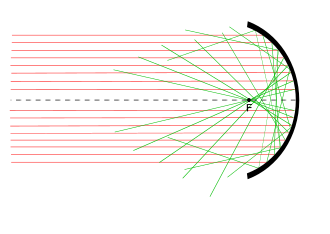
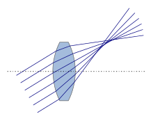
The spherical aberration , also called aperture error or spherical shape error, is a sharpness error and causes that axially parallel incident light rays or rays emanating from the same object point on the optical axis do not have the same focal length after passing through the system . They therefore do not come together in one point. In general, the further out the beam, the greater the deviation. The back focal length of the refracted ray is given by an even function for reasons of symmetry :
It is the center distance with which the beam enters the system and indicates the strength of the spherical aberration of the kth order. is the paraxial back focal length of the refracted ray.
Lenses with spherical aberration deliver a soft image with sharp, but low-contrast details, to which only the rays near the axis contribute. The off-axis rays create halos at light-dark transitions.
Motifs in front of and behind the plane of maximum sharpness are drawn differently out of focus. There are lenses whose spherical aberration can be continuously adjusted over a wide range in order to adjust the blur in front of and behind the focus and the sharpness in the focus.
With a system that contains only spherical (spherical) refractive or reflective surfaces, one cannot achieve a real image that is completely free of spherical aberration (see aplanatic image ). With an aspherical surface of a lens or a mirror, one can completely correct the spherical aberration. However, grinding a spherical surface is much simpler and therefore cheaper than grinding aspherically curved surfaces. The widespread use of spherical surfaces is based on the fact that they are considerably cheaper to manufacture, while their aberrations can be effectively reduced by combining several lenses. The costs for aspherically ground lenses are put into perspective in systems with many lenses, since the same image quality can be achieved with fewer lenses.
In the meantime, there are methods of producing high-quality aspheres in the form of pressed parts (molding), which is significantly cheaper. Smaller lenses can be pressed directly, and larger ones are produced by reshaping a spherical lens of equal volume. The size is limited by two problems: on the one hand, there are only a few types of glass that are suitable for reshaping, on the other hand, reshaped lenses tend to be inhomogeneity due to internal stresses that arise during the shaping process.
Small plastic lenses are manufactured inexpensively using the injection molding or injection compression molding process, but are not suitable for systems with higher demands on the image quality, such as camera lenses. You can also cast a plastic layer on a spherical glass lens and press it into an aspherical shape. This technology can also be used for photo lenses.
With the help of the Foucault cutting method, spherical aberrations can also be easily detected with simple means. Today, interferometric processes are common in the mass production of optical parts .
If the spherical aberration limits the resolution , this can be increased by stopping down to the critical aperture .
When reflecting on a spherical concave mirror, an imaging error occurs, this is called catacaustics .
astigmatism
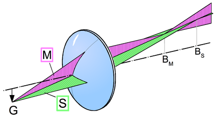
Astigmatism is an aberration of the "crooked" rays. A bundle of rays incident obliquely is refracted to different degrees in the meridional and sagittal planes . In the direction of the meridional plane (M), the lens is perspective shortened, which results in a shorter focal length.
As a result, no points are shown in the points (B M and B S ), but focal lines in the respective other plane. In front of and behind the two focal planes, instead of a circle, an oval is created, since each bundle of rays in a plane becomes an ellipse and has a different opening angle at each point. If a screen is held behind the sagittal focal plane, an oval with a long semi-axis in the meridonal direction (red) can be seen. Analogously, the oval in front of the meridional focal plane is with a longer semiaxis in the sagittal direction (green). In between there is a point where a point is depicted as a fuzzy circle, the smallest circle of confusion or confusion .
The astigmatism is characterized by the astigmatic difference , the distance between the focal lines. This distance increases with a greater inclination of the incident beam to the optical axis, with increasing lens thickness as well as the lens power and the lens geometry. So have z. B. bi-convex or bi-concave lenses in contrast to meniscus lenses have a particularly strong astigmatism. To correct the astigmatism of the eye , a targeted astigmatism is generated with the help of glasses and this image error is compensated.
An optical system can be designed to reduce or prevent astigmatism effects. Such optics are called anastigmates . This designation is only of historical significance, as this defect only occurs with serious manufacturing defects in modern lenses. The Schiefspiegler - a group of astronomical telescopes - represent an exception , in which the error is specially corrected.
An imaging error similar to astigmatism can occur in mirror telescopes used in amateur astronomy, which are often focused by axially shifting the main mirror. This can lead to small tilts, as a result of which the image of the stars is no longer point-shaped, but appears somewhat oblong when focused from the extra or intrafocal side horizontally or vertically.
coma
The coma (asymmetry error, from Latin coma 'head, tail') is caused by a superposition of two imaging errors when the bundle of rays incident at an angle to the optical axis: the spherical aberration, which also acts with a bundle parallel to the axis, and the oblique bundle astigmatism. Instead of a sharp diffraction disk, an image point is created with a “tail” directed towards the edge of the optics, which gives the phenomenon its name. The appearance can be reduced by blocking the marginal rays, but the astigmatism of oblique bundles remains.
Coma can occur with both lens and mirror optics. Optical systems in which both spherical aberration and coma are completely corrected are called aplanats .
Field curvature
Further article Petzval's image field curvature

If optics have a curvature of the field of view, the image is not generated on a plane, but on a curved surface - it is therefore a so-called positional error. The position of the ray intersection along the optical axis is then dependent on the image height, i.e. the further the object and thus image points are away from the axis, the more the image point is shifted in the axial direction (typically forwards, towards the objective).
Thus, on a flat projection surface, the image of a flat object cannot be shown sharply over the entire surface. If you focus on the center of the image, the edge is out of focus and vice versa.
Field curvatures are not only found in lenses, but also in other optical components, e.g. B. with eyepieces or projectors . However, like most other aberrations, it can be kept below the tolerance threshold by a special arrangement of the lenses (flat field optics).
Flat field optics are also required for scanners for laser engraving in order to process flat surfaces.
With some special cameras, on the other hand, the field curvature is compensated for by pressing the photographic film against a curved surface, for example with the Baker-Nunn satellite camera.
In digital cameras , curved image sensors can be used to compensate for image errors.
Distortion
Distortion is a positional error and means that the image height (distance of an image point from the center of the image) depends in a non-linear way on the height of the corresponding object point. One can also say: the image scale depends on the height of the object point. The image center is the point where the optical axis intersects the image plane. This is usually the center of the image, but shift lenses and view cameras also allow the optical axis to be shifted from the center of the image. The image center is also called the center of distortion or the point of symmetry of the distortion .
Distortion has the effect that straight lines that do not intersect the optical axis, i.e. whose image does not go through the center of the image, are shown curved.
If the image scale decreases with increasing height, this is called barrel distortion . Then a square with outwardly curved sides is shown, so it looks like a barrel (name). The reverse is called pincushion distortion . Then the square looks like a sofa cushion. Wavy distortion can also occur when different orders of distortion overlap. Straight lines are then curved to both sides like wavy lines.
Wide-angle lenses in retrofocus -construction ( -sectional width greater than the focal length ) tend to barrel distortion and telephoto lenses (length smaller than focal length) of the pillow-shaped.
So-called fisheye lenses have a strong barrel-shaped distortion. This is intended, on the one hand, to achieve a larger image angle (180 degrees and more are only possible through distortion) and, on the other hand, to use distortion for image design.
In binoculars , especially those with wide-angle eyepieces, a pillow-shaped distortion is often desirable in order to avoid the unpleasant globe effect when the glass is swiveled. The physical basis for this is the so-called “angle condition”, which should be fulfilled for binoculars (in contrast to the “tangent condition” for photo lenses).
Chromatic aberration
The refractive index of optical glass depends on the wavelength of the incident light. This phenomenon is called dispersion . It is the cause of the chromatic aberration .
Lateral chromatic aberration
The refractive index of the lenses of an optical system influences the image scale , which therefore depends on the wavelength. The partial images that are formed by light of different wavelengths are therefore of different sizes. This effect is called lateral chromatic aberration . It causes color fringes at the edges of the image motif, if these do not run radially, and a blurring of the image. The width of the color fringes is proportional to the distance from the center of the image.
Longitudinal color defects
The back focal length of the system, and thus the distance between the image and the last surface of the system, is also dependent on the refractive index of the lenses and thus on the wavelength of the light. As a result, the partial images of different colors cannot be sharply captured at the same time because they are in different positions. This is called longitudinal color defects . The result is a blurring that does not depend on the image height.
Gaussian error
The dispersion of the optical glasses causes the remaining aberrations to vary with the wavelength. If the coma is corrected for green light, it can still be present for red and blue light. This effect can significantly influence the quality of a lens and must be taken into account when designing high-quality systems. In the case of spherical aberration, this effect is referred to as Gaussian error, the designation often being extended to the other errors.
Achromat
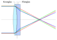
If lens glasses with significantly different Abbe numbers are used in a system , the color error can be greatly reduced. Specifically is meant by an achromat a lens, in which the change of the focal distance disappears with wavelength for a wavelength.
Apochromat
So-called apochromatically corrected objectives (apochromats) represent a further development. For these, glasses with an unusual dispersion behavior are used, whereby the secondary spectrum can also be corrected. In the classic version, these are calculated in such a way that the back focal lengths match at three wavelengths (e.g. red, green and blue), which means that the longitudinal color error is also very small for all other wavelengths of visible light. A reference to systems corrected in this way is usually the abbreviation APO on the lenses. As a rule, they are significantly more expensive than just achromatically corrected products.
Technically related aberrations
The errors described above follow from the mathematical laws of the figure. But there is also the fact that nothing in technology can be manufactured with perfect accuracy. With optical systems, too, there are deviations in the real dimensions and properties from the values specified during construction:
- Dimensional and shape deviations of the elements (lenses and mirrors)
- Deviations of the elements from their intended positions
- Different refractive index of the lenses
- Inhomogeneities ( streaks ) in the glass of a lens (see properties of optical glass )
- Residual stresses in the lenses and stresses due to the frame, which can lead to stress birefringence
As a result of these deviations, an optical system more or less lags behind the image quality that corresponds to its design. A deviation from the rotational symmetry can mean that the image quality depends not only on the distance from the center of the image, but also clearly on the direction, i.e. that the quality on the left edge of the image is noticeably worse than on the right. This is known as a centering error .
When designing a lens, it makes sense to include sensitivity to manufacturing errors in the optimization process. The accuracy with which the components must be manufactured in order to achieve a sufficient image quality is an important cost factor. In a finished construction of an optical system, the designer not only has to specify the target values for the geometry and glass properties, but also the permissible deviations .
Changes in environmental parameters, especially temperature, also cause deviations in shapes, dimensions and refractive indices. The components of an optical instrument expand when heated. With large astronomical instruments, a noticeable bending of the telescope can result from one-sided heating (as well as from their own weight). The refractive index of glass also changes with temperature. Among the camera lenses, those with a long focal length and good correction are particularly sensitive to temperature changes. They are therefore often given a white coating so that they are less heated by solar radiation.
Also, turbulence and temperature differences in the air layers of the Earth's atmosphere cause aberrations disturbing appear especially with large focal lengths and distant objects. In astronomy in particular, the atmosphere limits the resolution of a telescope . The limitation of resolution due to atmospheric influences is generally referred to as air turbulence , especially in astronomy as seeing . Furthermore, with stars near the horizon and with atmospheric halo appearances, a vertical color fringing can occur, because the astronomical refraction is slightly dependent on the wavelength of the light. To correct these influences, adaptive optics are used or the telescopes are stationed outside the earth's atmosphere ( space telescope ).
Axial astigmatism
Imperfect lenses that are not rotationally symmetrical about the optical axis can also image axially parallel bundles astigmatically. An object point is mapped as a line (lengthways or crossways) depending on the focus. This defect plays an important role in ophthalmic optics and electron optics . The simplest form of axial astigmatism can be corrected by combining it with a cylinder lens that is appropriately dimensioned in terms of refractive power and axial direction (cylinder lens in the glasses , stigmator in the electron microscope ). The manufacture of glass lenses for visible light is now so mature that there is no noticeable axial astigmatism.
See also
Individual evidence
- ↑ Barbara I. Tshisuaka: Eustachio Divini. In: Werner E. Gerabek , Bernhard D. Haage, Gundolf Keil , Wolfgang Wegner (eds.): Enzyklopädie Medizingeschichte . De Gruyter, Berlin 2005, ISBN 3-11-015714-4 , p. 316.
- ^ Next Generation: Changes in recording technology , film-tv-video.de, News - Reports, June 9, 2010, accessed on December 26, 2015
- ↑ Bernd Leuschner: Opening error of a planoconvex lens (PDF; 161 kB), Laboratory for Device Technology, Optics and Sensor Technology, Beuth University of Technology Berlin.
- ↑ Japanese Patent Application Number 2016-197661 - Domed Sensor with Non-Spherical Shape ( December 1, 2016 memento on the Internet Archive ), Toshiba, filed April 3, 2015, published November 24, 2016, accessed December 1, 2016.
literature
- Eugene Hecht: optics. 4th revised edition, Oldenbourg Wissenschaftsverlag, Munich et al. 2005, ISBN 3-486-27359-0 .
Web links
- Erwin Puts, Leica M Lenses - Your Soul and its Secrets (PDF, 1.4 MB, 83 S.) Introduction to almost all aspects of lens construction, including a glossary of image errors
- BAS®: Test procedure for lenses
- Representation and conversion of Zernike polynomials and Seidel aberration
Videos
- Video: spherical aberration . Institute for Scientific Film (IWF) 2004, made available by the Technical Information Library (TIB), doi : 10.3203 / IWF / C-14893 .
- Video: astigmatism . Institute for Scientific Film (IWF) 2004, made available by the Technical Information Library (TIB), doi : 10.3203 / IWF / C-14894 .
- Video: Chromatic Aberration . Institute for Scientific Film (IWF) 2004, made available by the Technical Information Library (TIB), doi : 10.3203 / IWF / C-14895 .


