Single-phase series motor
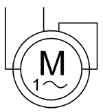
The single-phase series motor is an electric motor that can be operated with both direct and alternating current . It differs from the direct current series motor only in a few details. The single-phase series motor belongs to the group of AC commutator motors, which is why it is also called single-phase commutator motor. Smaller single-phase series motors are also known as universal motors or all-current motors. The single-phase series motor was developed around 1904 by Hans Behn-Eschenburg at Maschinenfabrik Oerlikon .
Basics
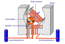
The single-phase series motor differs in its design from direct current series motor only in the compact stator package , which forms a unit with the pole pieces. To reduce eddy current losses caused by the alternating field , the entire magnetic circuit must be laminated ( dynamo sheet ). The principle of operation of the single-phase series motor is the same as that of the direct current machine. Because of the series connection of the armature and excitation windings, the excitation current (excitation field) and the armature current are in phase, i.e. the excitation current and armature current change their sign at the same time, the direction of force and direction of rotation remain the same.
Single-phase series motors are designed for AC voltage, but can also be operated with DC voltage. Conversely, however, a direct current motor cannot be operated with alternating current, since then mostly disruptive eddy currents in the stator and self-induced voltages would occur due to stray fields from the armature and excitation winding . Due to the inductive reactance, the output of AC voltage is 15% less than that of DC voltage. Small single-phase series motors are nowadays designed as universal motors up to a nominal output of 3 kilowatts and a nominal speed of 3000 to 30,000 revolutions per minute. Due to the high speed, these universal motors can be made smaller. Since the current density is very high in small motors , there is high power loss and the motor heats up. This problem is remedied by the high speed ( cooling ).
construction
The stator housing encompasses the entire motor structure and is a cast part for smaller motors and a welded construction for larger motors. Smaller motors can have cooling fins on the stator housing , while larger motors can have cavities to guide the cooling air. The motor consists of a stator with pronounced poles as in the DC motor, but which is designed as a laminated core. However, motors for high outputs no longer have pronounced poles; the stator in them consists of stamped dynamo sheet metal profiles. The magnetically active parts of the stator and armature are composed of “packages” of dynamo sheets isolated from eddy currents on one side. These are punched out as a complete ring or as individual segments. The laminated core is pressed or shrunk into the stand. Both stator and armature laminations are usually shaped in such a way that instead of just one, they have a large number of pole pairs.
The electrically active parts essentially consist of the stator or excitation winding ( excitation coil ) and the armature winding. The excitation windings and the armature winding are connected one behind the other or " in series ". If - as is usually the case - the field winding is symmetrical to the armature, the sub-coils of the field winding act like choke coils and contribute to radio interference suppression. The series winding has fewer turns than the shunt motor, but with a larger cross section. The windings made of enamelled copper wire are wound in the grooves of the stator and armature core or inserted as prefabricated windings ("stuffed"). Insulating material is placed in the grooves beforehand. For better electrical insulation of the wires from one another and for stabilization, the windings can be impregnated with lacquer or resin.
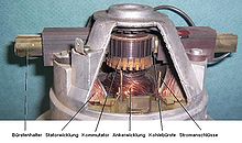
The rotating armature (rotor) does not differ from that of the DC motor. It consists of the armature laminated core attached to the axle shaft and the armature coil winding. The armature shaft is mounted in the stator housing and transmits the torque to the outside. The commutator or collector, through which the currents of the armature coil winding are conducted to the stator winding or to the connections via the carbon brushes installed in the stator, is attached to one side of the laminated core . The brush holder is used to hold the carbon brushes in the required position.
Fastening devices are provided on the stator housing according to the application. Traction motors for electric railways have special devices for resilient suspension between the support structure ( bogie or locomotive box) and the gear transmission on the wheelset axle.
Mode of action
principle
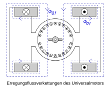
The current-carrying excitation winding in the stator generates a magnetic field that is reinforced by the sheet iron package and bundled into defined poles. The same happens in the downstream armature coil winding. This magnetic field built up by the stator causes, depending on how the poles are set, that it pulls the rotor behind it or pushes it in front of it. The polarity of the coils must be reversed every half turn (in machines with one pole pair), which requires a commutator.
If you consider a "single-pole" version only, both magnetic fields are perpendicular to each other. According to the laws of physics, forces arise which seek to combine the two magnetic fields into a unipolar common field. The armature is rotated by this force. However, since an electrical pole change occurs with every armature rotation on the commutator, the original state of the magnetic field is set anew every time, so that the armature continues to rotate as long as the current flows through the armature and excitation windings.
The continuously repeated polarity reversal caused by the alternating current has no influence on the running behavior, since both windings are always "reversed" at the same time. When operating with sinusoidal alternating current, the torque follows a sinusoidal curve with twice the mains frequency. The minima of this sinusoid are slightly negative. When operated with direct current, the commutator motor generates a torque that is constant over time .
Commutation

To turn the current, the brushes are shifted against the direction of rotation when the motor is running, the main pole flux induces a motion voltage in the commutating coil that supports the commutation. In generator mode, the brushes must be shifted in the direction of rotation; the brush shift depends on the operating status. Complete compensation is only possible at a certain operating point (nominal point). Shifting the brush to improve the current reversal leads to a weakening of the field of the exciter poles ( has an opposite component ); Note the stability of the machine.
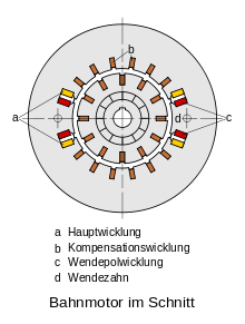
Since the commutator does not adapt itself (i.e. it always switches over perpendicular to the main field lines and not perpendicular to the "effective" field lines ), the brush fire can be reduced by mounting the brush holder slightly rotated and then switching perpendicular to the effective field lines when in operation. However, this requires adjustment during operation and is rarely carried out today for reasons of cost. Instead, reversing pole windings and compensation windings are used in large machines , which "bend" the field lines back into the ideal position. Reversible poles are only used in larger single-phase series motors such as the railway motor. Small single-phase series motors have no reversing poles and no compensation winding.
Problems
The sinusoidal polarity reversal of the stator field induces a voltage in the rotor which is dropped across the brushes. This transformer voltage cannot be compensated by shifting the brush. Therefore, in contrast to DC machines, there is an induced AC voltage on the carbon brushes, which leads to constant brush fire and high wear on the brushes (however, reversing-pole windings and compensation windings can help). In addition to the necessity of radio interference suppression for this motor by means of capacitors , this also greatly reduces the service life of the motor compared to rotary field machines.
Operating behavior
In the case of a single-phase series motor, the excitation current also falls, which leads to an increase in speed as the torque falls. This behavior of a motor is known as series connection behavior . It has no fixed limit speed, which means that larger units would run up without load until the armature bursts. For this reason, a centrifugal switch is mounted on the motor shaft for protection on some motors. This switch switches on an ohmic resistor at critical engine speeds or switches the engine off completely.
- At standstill when switching on, the highest current flows through the armature and stator windings.
- The series motor has the greatest starting torque of all electric motors .
- Series motors operated with no load or with little or no load run away with constantly increasing speed .
- Under load, the speed decreases, while the torque increases again due to the reduced speed, a stable state levels off.
- The speed is very load-dependent.
Mathematical consideration
Equivalent circuit diagram
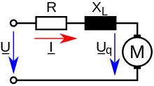
Since the machine is operated with alternating current, all inductive resistances must be taken into account in addition to the ohmic resistances of the windings . The reactances are combined to form a reactance :
- ... total reactance
- ... reactance of the excitation winding
- ... armature winding reactance
- ... reactance of the reversing pole winding (if present)
- ... reactance of the compensation winding (if present)
is the saturation of the magnetic circuit depends on (especially , the main field, stray field). therefore decreases with increasing load. is assumed to be constant for the further derivation.
Since the axis of the armature winding is perpendicular to the excitation winding, no transformer voltage is induced in the armature winding, that is, only the motion voltage is in phase with the field and current.
Torque
The torque is calculated analogously to that of the DC machine. For AC operation, the effective values are to be used for current and voltage .
with - internal torque - effective value of the current - excitation field strength (proportional to current I) - armature motor constant
The excitation field is generated by the current that flows through the armature and the excitation winding. Therefore the torque is proportional to the square of the operating current. The following applies when the machine is loaded:
- ... load moment
- ... moment of loss
The machine's moment of inertia and the load result in an average speed. As a result of the pulsating torque, however, an oscillating speed is superimposed on this average speed.
Torque equation derived from the internal power
The moment pulsates at twice the network frequency .
Voltages induced in commutating coil
Transformer voltage
The coil axis of the commutating coil coincides with the excitation field axis, that is, a transformer voltage is induced in the commutating coil by the variable excitation field.
- ... transformer voltage
- ... magnetic flux
- ... grid frequency
- ... number of turns per coil
The transformer voltage is proportional to the mains frequency, but independent of the speed (it also occurs at standstill) and leads the current by 90 °.
Reactance voltage
The reactance voltage counteracts the change in current. Commutation time = t K . The change in current depends on the commutation time → Reactance voltage depends on the commutation time.
- ... reactance voltage
Movement tension
Since the turning field varies sinusoidally over time, the induced motion voltage also depends on the commutation time.
- ... tension in the turning area
- ... peripheral speed of the armature
- … Magnetic flux density of the turning field
- + with reversible pole
- - without reversing pole
The transformer voltage cannot be compensated with the reversing poles.
- remedy
- Reversing poles + parallel resistance
The spark voltage can only be fully compensated for a certain speed. At a standstill, the transformer voltage cannot be compensated by the reversing poles, i.e. it must be kept small.
- remedy
- small → D - A - CH - traction power network with 16 2/3 Hz ,
- Flux per pole small → large number of pole pairs
Current location curve
The current locus provides a relationship for the current vector between the impedance and the speed n as a real variable. As with the asynchronous machine, inverting creates a circle. A fixed speed can be assigned to each current vector with a selected resistance scale. The lower half cannot be used to construct the current arrows in the generator mode, as is the case with the asynchronous machine.
The maximum current results for:
- … Electricity
- … Tension
- ... impedance
- ... fictitious synchronous speed (which a synchronous motor with the same structure would have)
- ... frequency
- ... number of pole pairs
- ... number of turns
- ... reactance of the excitation winding
- ... phase shift angle
- ... reactance
particularities
Special features compared to DC motors
The magnetic field of an AC motor pulsates with the frequency and induces a voltage that is harmful to commutation in the rotor windings short-circuited under the brushes . This voltage is called transformer voltage ( ); it is proportional to the frequency , the number of turns and the magnetic flux. The other voltages appearing in the short-circuited winding are:
- the reactance voltage ( ), which is proportionally dependent on the rotor current and the speed (the reactance voltage is created by reversing the polarity of the leakage flux of the commutating coil)
- the voltage ( ) resulting from the non-compensated rotor residual field , which is also dependent on the rotor current and the speed
These voltages are compensated for by the turning field voltage, which is also dependent on the rotor current and the speed. ', and together form what is known as the spark voltage . The transformer voltage cannot be compensated for the entire speed range with simple means. If one were to shift the phase of the reversing field voltage, the spark voltage could be completely compensated. This is possible by connecting an ohmic resistor in parallel to the reversing pole winding for a specific operating point.
The transformer voltage is greatest when starting up and must not exceed certain values. To keep it small, the following measures can be taken. These are usually only used for large engines:
- Reducing the excitation flow per pole (this leads to a large number of poles) in order to obtain high performance
- and number of turns equal to 1 and loop winding. This in turn requires a large number of rotor coils and therefore a large number of lamellas, which is limited for mechanical reasons.
In order to reduce the current driven by the transformer voltage, expanding carbon brushes are sometimes used , which increase the resistance between the short-circuited coils on the collector.
In order for the power factor to be as close as possible to 1, the rotational voltage must be high. This is possible thanks to a large number of lamellas, a low frequency and a high speed. The power is proportional to the number of pole pairs, the magnetic flux, the rotor current load and the rotor peripheral speed. The number of pole pairs is limited because of the possible design of the brush holder division. Because of the transformer voltage, the magnetic flux is limited, the rotor current coating for thermal reasons and the rotor peripheral speed for mechanical reasons. The motor voltage is determined by the number of lamellas and the number of pole pairs (because of the permissible lamella voltage). Caused by the inductive resistances, a phase shift occurs between the current and the voltage. The pulsating torque of twice the mains frequency is given a negative component depending on the phase shift. Reversing the direction of torque leads to high mechanical loads and shaking of the motors, especially when starting.
Operating a direct current shunt motor with alternating current would therefore make no sense, as the inductance of the stator would create a phase difference of 90 ° between the stator and rotor current, which would make the generated mean torque zero.
Differences between 16 2 / 3 - and 50 Hertz motors
For 50 Hertz engines, the same rules apply as for 16- 2 / 3 Hertz motors, only in this case the transformer voltage plays an even greater role. Because of the three times the frequency, this would also be three times as large. Therefore you have to take special measures to prevent this. With the same design principles can be, at the same transformational voltage, only one-third of the capacity of 16 2 / 3 reach Hertz motors. To prevent this, it is necessary to the magnetic flux to one third compared to 16 2 / 3 reduce -Hz engines, either shortened in the one the arm length to one-third or triples the number of pole pairs. However, the number of pole pairs cannot be increased at will (brush holder division!). The low frequency of 16 2 / 3 Hertz facilitates the commutation.
However, if the iron length is shortened to a third and the number of pole pairs is retained, two sub-motors can be accommodated on a common shaft; these motors are then called tandem motors. These motors then two thirds of the can at the same installation conditions power of 16 2 / 3 engines Hertz reach. Such tandem motors are, however, extremely complicated and expensive. Ultimately, they have, as well as 16 2 / 3 Hertz motors, become less important because Drehstromasynchronantriebe offer some advantages.
Speed setting
- Regulation of the terminal voltage
- → Reduce the speed. The speed characteristics are shifted downwards. With low voltages, and have a greater influence. The hyperbolic course of the characteristics changes somewhat.
- DC auxiliary winding
- In DC operation, there are no inductive voltage drops. With the same operating conditions (voltage, current), the no-load speed is therefore higher with direct current. The no-load speeds can be made equal by tapping the field winding.
- Winding taps
- If the number of turns of the excitation winding is reduced, the excitation field decreases with constant current → the speed increases.
- Series resistor
- With a constant current, the machine voltage is reduced by a series resistor, the speed-torque characteristic is shifted downwards. This speed setting method reduces the efficiency because the voltage at the series resistor drops.
- Parallel resistance
- The excitation current and the excitation flow are amplified by the current through the parallel resistor. The speed-torque characteristics are shifted downwards and flatter for a smaller parallel resistance. Since an excitation current also flows when idling (series resistor), the idling speed is limited.
- Barkhaus switch
- Combination of series resistor and parallel resistor enables a large speed range. The idling speed is set via the parallel resistor and the characteristic curve is shifted via the series resistor.
- Phase control
- With the phase control, a practically lossless and finely stepped control of the speed is possible. During a half cycle, the current is interrupted for a certain time, that is, the effective value of current and voltage are changed, which leads to a change in torque and speed.
Advantages and disadvantages
advantages
- Good speed setting options
- high torque at low speed
- large tightening torque (advantageous for agitators, switches, drills)
- Lower mass of iron and copper than an asynchronous motor of the same power (particularly advantageous for portable devices with high motor power, e.g. vacuum cleaner, drill)
disadvantage
- higher manufacturing costs than asynchronous machines
- Speed change under load ( hyperbolic curve) → a control is necessary for constant speed
- Brush apparatus, commutator in need of maintenance
- Brush fire
- Radio interference suppression necessary
Areas of application
Single-phase series motors (with small reversing poles and compensation windings) were previously used as rail motors . For this purpose, the operating voltage was stepped down from 15,000 volts to approx. 20 volts to approx. 600 volts using a traction transformer and the associated step selector. To avoid asymmetrical loads, large single-phase series motors must not be operated on the public grid .
Today, single-phase series motors as universal motors are among the most important small motors. In addition to the drive for power tools , this motor is used in practically every electrical household appliance. These devices are often equipped with a step switch that can be used to switch between taps of the field winding for different load cases. However, their short service life prohibits them from being used continuously.
Also in washing machines they are often to be found - but for this they must umpolbar and a tachometer generator to be equipped to be able to control direction and speed. The advantage here is that you can both wash and spin with a simple motor without changing gear.
Application examples
- domestic appliances
- vacuum cleaner
- Mixing, kneading and cutting machines
- mixer
- Washing machines
- Model railways (AC-powered models, Märklin brand)
- Power tools
- Hand drills
- Angle grinder
- Circular saws
Standards and regulations
- EN 60 034 Part 1 General provisions for rotating electrical machines
- EN 60 034 part 8 Terminal designations and direction of rotation for electrical machines
- DIN IEC 34 Part 7 Types of rotating electrical machines
- EN 60034-5 Degrees of protection of rotating electrical machines
- EN 60034-6 Types of cooling, rotating electrical machines
Individual evidence
- ↑ a b c d A. Senner: Electrical engineering. 4th edition. Verlag Europa-Lehrmittel, 1965.
- ↑ a b c d e Rolf Fischer: Electrical machines. 12th edition, Carl Hanser Verlag, Munich and Vienna, 2004, ISBN 3-446-22693-1 .
- ^ A b c d e Franz Moeller, Paul Vaske (ed.): Electrical machines and converters. Part 1 structure, mode of operation and operating behavior, 11th revised edition, BG Teubner, Stuttgart 1970.
- ↑ a b c Wilhelm Raith: Textbook of Experimental Physics, Volume 2. Electromagnetism . 8th completely revised edition, Walter de Gruyter GmbH & Co. KG. Berlin New York 1999, ISBN 3-11-016097-8 .
- ^ A b Wilhelm Philippi: Electric power transmission . Published by S. Hirzel, Leipzig 1905.
- ^ A b c Germar Müller, Bernd Ponick: Fundamentals of electrical machines . 9th edition, Wiley-VCH Verlag GmbH & Co KGaA., Weinheim 2006, ISBN 3-527-40524-0 .
- ↑ a b c d e Günter Boy, Horst Flachmann, Otto Mai: The master's examination in electrical machines and control technology. 4th edition, Vogel Buchverlag, Würzburg, 1983, ISBN 3-8023-0725-9 .
- ^ Günter Springer: Electrical engineering. 18th edition, Verlag Europa-Lehrmittel, Wuppertal, 1989, ISBN 3-8085-3018-9 .
- ↑ a b c Ekbert Hering, Alois Vogt, Klaus Bressler: Manual of electrical systems and machines. Springer-Verlag, Berlin Heidelberg New York 1999, ISBN 3-540-65184-5 .
- ↑ a b c d Ernst Hörnemann, Heinrich Hübscher: Electrical engineering specialist training in industrial electronics. 1st edition. Westermann Schulbuchverlag GmbH, Braunschweig, 1998, ISBN 3-14-221730-4 .
- ↑ Heinz M. Hiersig (Ed.): VDI-Lexikon Maschinenbau. VDI-Verlag GmbH, Düsseldorf 1995, ISBN 9783540621331 .
- ^ A b c d Georg Flegel, Karl Birnstiel, Wolfgang Nerreter: Electrical engineering for mechanical engineering and mechatronics . Carl Hanser Verlag, Munich 2009, ISBN 978-3-446-41906-3 .
- ↑ TU Ilmenau series-wound motor (accessed on June 13, 2016).
- ^ Andreas Kremser: Electrical machines and drives, fundamentals, motors and applications. 2nd edition, Teubner Verlag, Stuttgart, 2004, ISBN 3-519-16188-5 .
- ^ Detlev Roseburg: Electrical machines and drives. Fachbuchverlag Leipzig in Carl Hanser Verlag, 1999, ISBN 3-446-21004-0 .
- ^ Hans-Dieter Stölting, Eberhard Kallenbach: Manual electrical small drives . Carl Hanser Verlag, Munich Vienna 2006, ISBN 978-3-446-40019-1 .
- ↑ In- depth topic: The engines of the model railway locomotives, part 1 ( Memento of the original from January 29, 2015 in the Internet Archive ) Info: The archive link was automatically inserted and not yet checked. Please check the original and archive link according to the instructions and then remove this notice. (last accessed on June 13, 2016).

