
Driver Machine Interface

The Driver Machine Interface ( DMI ) is used in the European Train Control System European Train Control System (ETCS) as an interface between the driver in the cab and the train . In the German-speaking area, the term is inconsistent and a. as cab display , display , display , screen , plant for screen input , ETCS display , ETCS-cab display , cab display or man-machine interface translated.
The driver and the ETCS vehicle equipment can communicate directly with one another via the DMI . It visualizes the currently most important information about the train journey - including the speed, current signals from the train protection system and the technical status of the locomotive - and must therefore be placed in the driver's immediate field of vision.
The DMI is part of the ETCS vehicle reference architecture. The structure of the DMI is based on the UIC standard 612-0x. It can be operated either with a touch screen or with a keyboard ; the standard provides for corresponding functional designs for both variants. The information presented and the interaction between the train driver and the DMI are the subject of document ERA_ERTMS_015560 , which is a binding part of the current ETCS specification ( Baseline 3 ).
Man-machine interface
According to UIC standard 612-0x, the driver's cabs of locomotives must be equipped with four standardized and universally applicable DMIs. The structure of the ETCS-DMI is defined with pixel accuracy. The cut-out area is 310 × 214 mm² with a screen diagonal of 10.4 inches and 640 × 480 pixels . More modern DMIs can offer a screen diagonal of up to 12.4 inches and more pixels.
From a large number of information, essential data should be prioritized and summarized in the DMI. Acoustic signals are intended to draw attention from the route to the DMI and point out important visual information (e.g. imminent emergency braking ). The standardized operator guidance supports the focus on particularly important information by dimming or hiding less important information. The basic design goal for the DMI was to provide the driver with the right amount of information and not to over- or under-demand.

The structure of the display is divided into six main fields, from top left to bottom right these are (status: 2004):
- The Watched distance information (Engl. Supervised Distance Info ) only with an active braking curve display. This can be the display of the target distance, the time until an intervention, the prediction of the speed at a certain point or the prediction of the exact location at which the train will come to a standstill.
- The field for speed control (Engl. SpeedInfo ) contains information about the braking curve and speed monitoring. This information only needs to be displayed when the vehicle is in motion; when the vehicle is stationary, it can be used for other functions, such as data entry.
-
In the field for additional driving information (English. Supplementary Driving Info ), for example, the ETCS level, a recommended speed, deviations from the timetable or information on national train control systems ( Specific Transmission Module , STM) can be displayed.
 DMI while driving with the STM LZB
 - The field for planning future events (also preview area , English planning ) contains a preview of the route information relevant to the individual train journey. For example, the speed profile of the train, announcements of level crossings or stations or commands can be displayed. If necessary, a second level enables detailing. This should enable the driver to better separate safety-relevant / immediate and non-safety-relevant / predictive information. When braking curve monitoring is started, the field is dimmed in order to draw attention to the most important information and thus increase the safety of the overall system. The scale of the forecast can be set in 6 steps from 1 to 32 km.
- The two fields for monitoring technical systems (engl. Monitoring ) are arranged below the two aforementioned fields. For example, they can contain information on door control, air conditioning, national train control systems, radio or the time. This information, which goes beyond the ETCS core functionality, is intended to provide a representation of all information relevant to the driver. Separate displays should only be necessary for data of technical diagnoses and details.
- The field for driver inputs (Engl. Driver input ) allows you to enter various tensile and driver data.


Functions for automated driving (ATO) and driver assistance systems (DMI) can also be integrated into the DMI. In ATO operation, for example, a countdown to the scheduled departure time is displayed during a traffic stop.
Display of monitored speeds
Using odometry, ETCS continuously determines the actual speed of the vehicle and compares this with the minimum permissible speed of the vehicle and the route that is transmitted via Eurobalise or via radio (via RBC , in ETCS levels 2 and 3 ). This is the basis for the path and speed monitoring of the vehicle and the task of the ETCS vehicle equipment (Onboard Unit, OBU). The DMI is used to display the current values.
In the ETCS-mode full monitoring (engl. Full supervision , FS) is made between monitoring various conditions.
Target speed
Monitoring of the target speed ( Ceiling Speed Monitoring , CSM), if compliance with a constant maximum speed is monitored and no speed change to a lower speed is pending:
- Normal state when the actual speed of the train is below the monitoring limit and no speed reduction is expected. The speedometer circle ( hook ) then indicates the target speed in dark gray.
- Exceeding the speed limit is indicated when the actual speed is around 2 to 3 km / h above the monitoring limit. On the circular speed display, the range between the permissible speed and the intervention speed (when ETCS issues a brake command) is shown in orange, the speedometer needle is also colored orange and an acoustic signal is emitted once. The colored warning disappears as soon as the actual speed of the train falls below the monitoring limit again.
- The warning status is activated as soon as the actual speed of the train exceeds the monitoring limit. conversely, it is deactivated again when the actual speed of the train is below the permissible monitoring speed again. The visual representation corresponds to that of exceeding the speed limit, an acoustic warning signal sounds continuously.
- A braking intervention takes place as soon as the actual speed of the train exceeds the value of the intervention speed ( first line of intervention ). In the circular speed display, the area between the permitted and actual speed is shown in red, the speedometer needle is colored red and a symbol for the brake intervention appears below the level display. The brake intervention display goes out as soon as ETCS no longer issues a brake command.

Speedometer when driving up to / below the target speed, without an active braking curve

Speedometer if the permissible speed is exceeded slightly (164 instead of the permissible 160 km / h)

Speedometer when the permissible speed is significantly exceeded (167 instead of the permissible 160 km / h)

Speedometer when the permissible speed is significantly exceeded (174 instead of the permissible 160 km / h) with ongoing brake intervention (symbol bottom left)


Target speed
The target speed monitoring (Engl. Target Speed Monitoring , TSM) begins with announcement of a new, lower speed limit. To this end, ETCS braking curves used.
- The announcement Monitoring (Engl. Pre-Indication Monitoring , PIM) begins ten seconds before reaching the required braking curve and ends at the point at which the required braking curve is reached. The area of the impending speed reduction and the speedometer needle are displayed in white. In addition to one-off acoustic information, the distance to the target is shown as the distance up to which the announced lower speed must be observed, to the left of the speedometer as a bar chart with a meter value. The announcement monitoring has been omitted with SRS 3.6.0.
- Over-speeding, warnings and braking interventions are carried out according to the monitoring of the target speed.

Announcement monitoring from currently still permissible 160 km / h to 60 km / h within 1320 m

Braking within the braking curve (at a permissible 143 km / h, the actual speed is 128 km / h.)
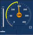
The permissible speed is slightly exceeded during braking. (At a permissible 143 km / h, the actual speed is 146 km / h.)

Significantly exceeding the permissible speed during braking. (At a permissible 128 km / h, the actual speed is 135 km / h.)


ETCS can manage several braking target points. Only the most relevant target point (“Most Relevant Displayed Target”, MRDT) is shown to the driver.
Release speed
The release speed monitoring (engl. Release Speed Monitoring RSM) serves to compensate for inaccuracies of the odometry, and allows, at low speeds up to a ETCS stop panel preferable or to drive a "proceed" signal at danger. The release speed is shown in light gray on the outer edge of the circular speed display. Shortly before an ETCS stop, the release speed can be greater than the permissible speed.
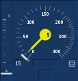
- Representation of the approach to a signal with 15 km / h release speed in the driver's cab display (DMI)

190 m before the end of the target speed monitoring (TSM) and the nominal curve at 48 km / h, the release speed is (h 15 km /) still do not use them ...

... also 50 m before the end of the TSM (target curve at 30 km / h).

20 m before the end of the TSM, the speed monitored by the target braking curve (8 km / h) has fallen below the release speed. Due to the release speed of 15 km / h, the approach is tolerated at 12 km / h.
After the TSM has expired, on the last meter before the signal, the signal is slowly approached using release speed (at 8 km / h).


Other modes of operation
When driving on sight (ETCS operating mode ETCS precautionary order , English On Sight / OS ) the displays are reduced to a minimum in order not to distract the driver unnecessarily from the route observation and to create a clear differentiation from driving in full surveillance. The permissible speed is only indicated by a tick on the edge of the speedometer disc; the circular speed display is dispensed with. An additional display of the target distance and release speed (digital only) can be activated with a toggle key.
In the ETCS command travel mode ( Staff Responsible , SR) only the actual speed is displayed. The permissible speed, the target distance and the target speed are only displayed on request from the driver.
In the ETCS signal- controlled operating mode ( Limited Supervision , LS), only the actual speed, the permissible speed ( defined as a national value ) and a few monitoring variables are displayed. The brake announcement is dispensed with in order to ensure the independence of the signal information transmission channels - as is the case with punctual train control . Visual and acoustic information is only given immediately before the brake intervention due to excessive speed (warning). A special feature of the operating mode is the display of the lowest monitored speed of the travel permit ( Lowest Speed supervised within Movement Authority , LSSMA ), which can be switched on, off or delayed by a balise telegram. If necessary, it is displayed as plain text in the top left of the DMI and replaces the tachometer circuit ( hook ) displayed in other operating modes .
In automated driving (mode AD ) warning tones are suppressed.
conditions
Data input and output for locomotive personnel


The display and control elements of ETCS can be used flexibly under program control. In contrast to earlier train control systems, ETCS requires a display. Entries can be made via touch-sensitive screens ( touchkey ) or keys ( softkeys) .
EVC coupling
RS485 , Profibus , Ethernet or MVB are used for communication between the ETCS vehicle computer ( European Vital Computer , EVC) and the DMI (status: 2011). The EVC manufacturer often also supplies the DMI; Occasionally, however, it is also supplied by another supplier or the vehicle manufacturer. Often, security protocols are used for secure data transmission.
Inputs and outputs at the DMI are stored in the ETCS trip data recorder ( Juridical Registration Unit , JRU). In some cases, encrypted connections between EVC and DMI are required, also to protect against cyber attacks. There are no uniform requirements for such encryption components.
Around 2017, an FFFIS interface definition between DMI and EVC was presented with the subset 121. This is not part of the ETCS specification and its application is not binding.
High availability
If the ETCS-DMI fails, the train comes to a standstill. A remedy can be to install two displays with the same function, for example by dividing the 10.4-inch display into two 8-inch displays arranged vertically next to each other. If one of the two displays fails in such a solution, the remaining display can show the necessary safety-relevant information (e.g. speed), while non-safety-relevant content is not shown. Switching from two-display mode to one of the two displays can be done using a rotary switch, for example.
If driver's cabs are equipped with four DMIs in accordance with UIC specification 612-0x, the failure of one DMI can generally be compensated for by other displays.
Higher redundancy requirements for the DMI can lead to higher hardware costs.
Extended temperature and environment tolerance
According to UIC 601, DMIs must a. support an extended temperature range and offer IP 65 protection on the front and protective coating of the electronic components. In the case of completely closed housings, a fanless design is required, which means that the waste heat must be kept low.
Certain areas of the display can be specifically monitored and the actual and target status can be compared with one another.
Real time
During operation, a new window must be displayed within two seconds of input from the driver.
After activating the driver's cab, the dialog for entering the driver's number ("Driver ID") must be displayed within three seconds. Between activation of the driver's cab and activation of the shunting mode (Mode SH ), regardless of the input of the train number and the request for the shunting mode , a maximum of 15 seconds may pass.
history
In the first ETCS project description from 1991, the creation of harmonized interfaces between the ETCS onboard unit and other peripheral systems of the vehicle equipment, such as the DMI, was planned.
In the course of interoperability in rail traffic ( TSI ), a solution for a uniform European DMI had to be found according to a specification of the European Commission , which can be used by the vehicle operators and manufactured by the industry without any problems. In addition to ETCS, EIRENE (GSM-R) should also be mapped in the DMI .
The development of such a Europe-wide uniform DMI was carried out under the stipulation of maximum user ergonomics initially by the A200 working group on behalf of the UIC.It began in 1991 with an orientation for various railways. In 1992, surveys and workshops with European experts in driving locomotives followed. The design was worked out in 1992 and 1993 and test and simulation were developed in parallel. Around 35 experts from 13 railways were involved. Six experimental designs were created. In 1993, simulator tests followed with 130 drivers from various European countries. From 1994 to 1996 design and specification as well as further investigations into data input (softkey, touchscreen, dialog structure) took place. A total of 240 drivers had the opportunity to express their views and comments on the DMI. The first description of a uniform operating and display device, which was included in the first system requirements specification (SRS A200) , is considered to be a significant advance achieved through ETCS.
In the mid-1990s, the ETCS vehicle architecture provided for a non-secure management computer (MC) in addition to the European Vital Computer (EVC, for safety-relevant systems) . He was responsible for functions and a. the control of the operating devices known at the time as MMI , which were therefore not included in the EVC's safety verification. By 2000, however, control was the responsibility of the EVC.
In 1998, a CENELEC working group made up of specialists from European railways and industry was commissioned to convert this draft into an interface specification. On the basis of functional (FRS) and program requirements specification (SRS), from 1998 the so-called 9D working group developed a DMI description for ERTMS, ETCS and EIRENE. A uniform philosophy and representation in the ETCS-DMI should also reduce the risk of human errors . While the input and display of ETCS information was firmly defined, specific technical devices or solutions (e.g. touchscreen or softkey) were left open to give operators flexibility. Various drafts were presented and revised.
As part of the DMI design, for example, the right amount of information to be conveyed and its degree of abstraction (e.g. "0 km / h" or "red") had to be decided. It was necessary to ensure that the interface is equally suitable for beginners and experts and can be used for changed framework conditions (e.g. relocation of trackside and signal information to the driver's cab). In addition, the system had to be designed with human perception in mind, for example appropriate acoustic support for changes in the visual representation.
The EVC-DMI interface was not defined at the FFFIS level. The EVC manufacturer defined the DMI requirements, including the SIL requirements. Since the communication between the DMI and the ETCS on-board computer was not standardized, two variants emerged over time:
- The DMI served as a terminal for the EVC, i.e. H. the display is controlled by the EVC.
- The DMI served as a standalone unit and makes its own decisions based on information received from the EVC.
CENELEC issued the DMI specifications by September 2005. Although these versions were not binding, most ETCS suppliers adhered to them. The design of the surface took into account the various requirements of railway infrastructure and transport companies. The focus was on operation via touchscreen. There was considerable room for interpretation, especially with regard to operation via softkey.
The presentation of ETCS and GSM-R information in a common DMI should simplify the vehicle equipment and save costs. However, this approach was not adopted for implementation (status: 2009).
In ETCS Baseline 2 , the display was not part of the ETCS specification (SRS, FFFS), but a CENELEC-compliant display was one of the basic ideas. Nevertheless, there were significant differences between the user interfaces of different manufacturers. The DMIs fulfilled safety requirements between the safety requirement levels SIL 0 and SIL 2.
In 2005, the ERTMS Users Group issued a draft of "Operational DMI information" in which - based on the CELENEC draft of 2005 - those parts of the DMI that were to be described as binding were described.
2007 took European Railway Agency (European Railway Agency, ERA Engl.) Setting forth the DMI specification. A first version consistent with ETCS subset 026 appeared in December 2008. The specification describes two variants - touchscreen and softkeys - which are identical on a functional level. Among other things, touchscreen and softkey operation have now been described in equal detail. With the introduction of ETCS Baseline 3 , a binding specification of the ETCS-DMI came into force for the first time. In this way, the presentation of all ETCS-related information should be designed uniformly across Europe.
DMIs according to baseline 3 must now be SIL 2 safe. According to a press report, the ERA had set these higher requirements under pressure from Germany. This means that when you upgrade from Baseline 2 to Baseline 3, displays have to be replaced early, which leads to considerable costs. The Swiss Federal Office of Transport sees no discernible benefit in this. Vehicles that only run in Switzerland would not have to meet the new safety requirements.

As part of the ETCS equipping of over 240 vehicles ("second wave") in Switzerland , which began in 2012 , in addition to the requirements of ETCS, elements of national train control, the central and one-off input of operating and train data, the determination related suggested values as well as the display of machine-technical indicator lights implemented. In particular, this should simplify and accelerate the input of operating and train data before the start of the train journey.
Others
An ETCS-DMI was used for the radio operation (FFB) developed for Expo 2000 . According to other sources, the FFB-DMI "[b] is in a few insignificant details the ETCS-DMI".
In the Netherlands, driving recommendations are displayed on the drivers' tablets in an ETCS-DMI-like form.
When integrating ETCS into existing vehicles (retrofit), the driver's desk sometimes has to be redesigned to create space for the ETCS DMI.
If a national train control system is integrated into ETCS as a Specific Transmission Module (STM), this is usually also integrated into the DMI. Alternatively, national train control systems can be integrated separately. Their operating devices remain in the vehicle and are not integrated into the ETCS-DMI. One advantage of a uniform DMI for ETCS and all other Class B systems is the avoidance of train driver training costs . When the vehicle is started, ETCS is active as a train control system; the selection of a national system requires separate operator action by the driver.
The test specification (subset 094) prescribes a touch or softkey display as an interface for testing the ETCS vehicle equipment. Direct stimulation of the interface between DMI and EVC is not permitted. The inputs to be made on the DMI can be made automatically by a robot, for example.
literature
- CENELEC (Ed.): TS 50459-1: 2005 . Part 1: Ergonomic principles for the representation of the ERTMS / ETCS / GSM-R information (= web turns - Communication, signaling and processing systems - European guidance system for rail traffic - human-machine interface - . Band 1 ). 2005 (European standard).
Web links
- ETCS specification , in particular DMI specification (document ERA_ERTMS_015560 ) in the current version 3.6.0 as well as previous version 3.4.0 and version 2.3.0 on the website of the European Railway Agency (ERA)
- ETCS manual for train drivers in Word and HTML format on the homepage of the European Railway Agency.
- Driving under ETCS L1 control . Split-screen video of a trip under ETCS Level 1 with the DMI displayed.
- ETCS for hobbyists: driving and braking and operating modes OS, SR and override . Videos with a description of the processes in the DMI in normal and fault mode.
Individual evidence
- ↑ ETCS specification , subset 023, version 3.3.0, section 5
- ↑ a b c d Rainer Eschlbeck: The European Train Control System . In: Your train . No. 6 , June 2010, ISSN 0948-7263 , p. 20-24 .
- ↑ Michael Fußy: VDE 8: ETCS Level 2 without signals - first application in Germany . In: ZEVrail . tape 138 , no. September 9 , 2014, ISSN 1618-8330 , p. 374-380 .
- ↑ Marc Joseph, Michael Tobler: Free travel in Switzerland for ETCS Level 2 with Siemens Trainguard 200 and "Switzerland Package" . In: Eisenbahn-Revue International . 2015, ISSN 1421-2811 , p. 492-494 .
- ↑ Christoph Gralla: Cost saving effects with the ETCS implementation on the vehicle as well as on the infrastructure side . In: Railway technical review . No. 7 , July 2013, ISSN 0013-2845 , p. 30-36 .
- ↑ First commercial top speed of 200 km / h in Switzerland . In: Swiss Railway Review . No. October 10 , 2007, ISSN 1022-7113 , p. 508 .
- ^ Gotthard delays: Findings and measures taken by the SBB . In: Eisenbahn-Revue International . No. 6 , June 2016, ISSN 1421-2811 , p. 274-277 .
- ↑ Peter Gerber: The signal forest is also being expanded with ETCS . In: Swiss Railway Review . No. 2 , February 2015, ISSN 1022-7113 , p. 94-96 .
- ↑ Stefan Rameder: ETCS at ÖBB: The start of a new era of train protection . In: Eisenbahn-Revue International . No. 5 , May 2010, ISSN 1421-2811 , p. 222-225 .
- ^ A b Ines Hamberger: ETCS operation of the Westbahn between Vienna and Salzburg . In: ZEVrail . tape 140 , no. 8 , August 2016, ISSN 1618-8330 , p. 292-297 .
- ↑ a b c Uwe Dräger: ETCS and the transition to the national train control systems of DB AG . In: signal + wire . tape 96 , no. 11 , 2004, ISSN 0037-4997 , p. 6-15 .
- ↑ a b c d e f g h i j k l m n o p q r s t u v w x Rainer Eschlbeck: ETCS from the point of view of the driver . In: Your train . No. 6 , June 2012, ISSN 0948-7263 , p. 36-40 .
- ↑ ETCS specification , subset 023, version 3.3.0, section 4
- ↑ a b Werner Geier: The driver's cab of modern electric locomotives . In: Swiss Railway Review . No. December 12 , 2002, ISSN 1022-7113 , p. 550-554 .
- ↑ ETCS specification , subset 091, version 3.3.0, section 4.3.
- ↑ a b c d e f Dana Schiffer: Redundant and secure - requirements for a modern DMI in ETCS . In: Railway technical review . tape 2016 , no. 9 , September 2016, ISSN 0013-2845 , p. 70-72 .
- ↑ ETCS specification , document ERA_ERTMS_015560, version 3.6.0
- ↑ a b c d Gunther Gräbner: Driver Machine Interface with AMD Embedded G-Series APUs . In: Railway technical review . No. December 12 , 2018, ISSN 0013-2845 , p. 62 f .
- ↑ a b c d e f g h i j k l m n o p q r Ulla Metzger, Jochen Vorderegger: "Human Factors" and ergonomics in ERTMS / ETCS - uniform display and operation . In: signal + wire . tape 96 , no. 12 , 2004, p. 35-40 .
- ↑ a b c The future of ETCS in Germany . In: Union of German Locomotive Drivers (Ed.): Advance . No. 9/10/11/12 , 2018, ISSN 1438-0099 , S. 27/24 f. / 24 f. / 24–26 (appeared in four parts in issues 9/2018 to 12/2018).
- ^ Paul Booth: ETCS and ATO through the Thameslink core . In: Railway Gazette International . No. 9 , September 2015, ISSN 0373-5346 , p. 33-37 .
- ↑ Manuel Villalba: Pioneering ATO over ETCS Level 2 . In: Railway Gazette International . tape 172 , no. 9 , 2016, ISSN 0373-5346 , p. 107-109 .
- ↑ Markus Pelz, Thomas Griem: Energy-efficient automation solutions for rail traffic . In: ZEVrail . tape 139 , no. 8 , August 2015, ISSN 1618-8330 , p. 284-290 .
- ↑ a b Niels Neuberg: The use of ETCS Level 1 Limited Supervision at Deutsche Bahn AG . In: signal + wire . tape 106 , no. December 12 , 2014, ISSN 0037-4997 , p. 12-18 .
- ↑ ETCS specification , subset 026, version 3.6.0, 3.13.10.3.9
- ↑ ETCS specification , subset 026, version 3.6.0, 3.13.10.4.2
- ↑ Thorsten Büker: ETCS Level 1 LS (ESG) under the aspect of performance . In: Railway technical review . No. 11 , November 2017, ISSN 0013-2845 , p. 24-31 .
- ↑ ERA , UNISIG , EEIG ERTMS USERS GROUP (ed.): ATO over ETCS . System Requirements Specification. May 4, 2018, p. 23 (Section 7.1.3.5) (SUBSET-125-010.docx file in ZIP archive [accessed April 25, 2019]).
- ↑ a b c d e f g Olaf Mense: The on board interfaces . In: Peter Stanley (Ed.): ETCS for engineers . DVV Media Group, Hamburg 2011, ISBN 978-3-7771-0416-4 , p. 193-198 .
- ↑ a b c d e f Patrick Deutsch: ETCS Driver Machine Interface DMI . In: Compendium on ERTMS . Eurailpress, Hamburg 2009, ISBN 978-3-7771-0396-9 , pp. 113-115 .
- ↑ Bernd Gonska, Oliver Röwer, Lennart Asbach: Reconstruction of operational scenarios from JRU records for laboratory tests . In: signal + wire . tape 107 , no. 4 , April 2017, ISSN 0037-4997 , p. 21-26 .
- ↑ a b c Roland Stadlbauer: Efficient equipping of rail vehicles with ETCS using the example of Slovakia . In: signal + wire . tape 108 , no. 11 , November 2016, p. 29-37 .
- ↑ CONTRIBUTING TO SHIFT2RAIL'S NEXT GENERATION OF HIGH CAPABLE AND SAFE TCMS AND BRAKES. (PDF) D3.1 - Drive-by-Data Requirement Specification. June 20, 2017, p. 34 , accessed December 28, 2019 .
- ↑ ERTMS certification. In: era.europa.eu. European Railway Agency, accessed on December 28, 2019 (English): "Subsets 119, 120 and 121 are NOT mandatory at the moment."
- ↑ ETCS specification , subset 041, version 3.2.0, section 5.2.1.0.
- ↑ ETCS specification , subset 041, version 3.2.0, section 5.2.1.11.
- ↑ ETCS specification , subset 041, version 3.2.0, section 5.2.1.12.
- ↑ a b Peter Winter : Conclusion and outlook . In: Compendium on ERTMS . Eurailpress, Hamburg 2009, ISBN 978-3-7771-0396-9 , pp. 235-242 .
- ↑ a b Peter Winter: ETCS project history . In: Compendium on ERTMS . Eurailpress, Hamburg 2009, ISBN 978-3-7771-0396-9 , pp. 69-80 .
- ^ Jens Hartmann: Migration of ETCS in the network of the Deutsche Bahn . In: Your train . No. 3 , March 2008, ISSN 0948-7263 , p. 33-38 .
- ^ Bernhard Ptok: ETCS - core of the "European Railway Traffic Management System" . In: The Railway Engineer . No. 3 , March 1996, ISSN 0013-2810 , pp. 56 ff .
- ↑ Hartmut Thies, Andreas Wik: The SBB's FSS pilot project - the world's first application of ETCS Level 2 . In: signal + wire . tape 92 , no. September 9 , 2000, ISSN 0037-4997 , pp. 16-24 .
- ↑ a b Lennart Asbach, Hardi Hungar, Karsten Lemmer, Michael Meyer to Hörste: formalization of tests for highly automated test execution . In: signal + wire . tape 106 , no. 9 , 2014, ISSN 0037-4997 , p. 26-34 .
- ↑ ETCS in Switzerland: Current status and challenges . In: Swiss Railway Review . No. 6 , June 2018, ISSN 1022-7113 , p. 300 .
- ↑ Andreas Indermühle, Peter Knechtsberger: ETCS equipment of over 240 vehicles in the train of the Swiss ETCS strategy implementation . In: signal + wire . tape 106 , no. 5 , 2014, ISSN 0037-4997 , p. 13-17 .
- ↑ Florian Kollmannsberger: Telematics as an important component in the overall rail system . In: Railway technical review . tape 49 , no. November 11 , 2000, ISSN 0013-2845 , pp. 734-739 .
- ↑ Werner Geier: The new human-machine interface of the BR 185 locomotive . In: Swiss Railway Review . No. 9 , September 1999, ISSN 1022-7113 , p. 366-374 .
- ^ Murray Hughes: Every second counts s . In: Railway Gazette International . tape 175 , no. 1 , 2019, ISSN 0373-5346 , p. 36-40 .
- ^ Klaus Mindel, Oliver Scheck: Economical equipment of locomotives with ETCS . In: ZEVrail (= conference proceedings SFT Graz ). tape 135 , 2011, ISBN 978-3-85125-175-3 , pp. 32-39 .
- ↑ Gerwin Smulders, Lieuwe Zigterman: Certification of ERTMS for European locomotives: theory and practice . In: signal + wire . tape 104 , no. 3 , March 2012, ISSN 0037-4997 , p. 32-36 .
- ↑ Aki Härkönen, Jörgen Öhrström: STM: The nordic experiences in a joint development project . In: signal + wire . tape 99 , no. 12 , 2007, ISSN 0037-4997 , p. 34-37 .