
Power transformer
As a power transformer is called an electrical transformer , of for services ranging from 10 M VA is designed to about 1000 MVA. This class includes devices in electrical energy networks that are often designed as three-phase alternating current transformers , but also single-phase ones for traction power supply . If required and with a correspondingly high output, three individual single-phase power transformers can be interconnected to form a so-called three-phase current bank, which then works like a three-phase AC transformer.
Areas of application
The structure of the various types differs depending on the area of application. In larger power plants, machine transformers are used to transform the generator voltage of a few 10 kV to the voltages of several 100 kV that are common in high-voltage networks. The power range is between a few 10 MVA to just over 1000 MVA.
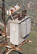
Network coupling transformers are used in substations . In larger substations, these serve as a hub for the national transport networks in order to connect the various voltage levels such as the 110 kV, 220 kV or 380 kV levels common in Europe. The power range covers some 100 MVA. In some substations, phase-shifting transformers are used for the targeted control of load flows on individual lines. Smaller power transformers in the range of a few 10 MVA are used in subordinate substations for supplying medium-voltage networks . The range from a few 10 kVA to a few MVA is used in the local transformer stations that serve to supply the low-voltage networks and are referred to as distribution transformers.
Special power transformers are the converter transformers , which are used to supply or connect power converters, which are now usually electronic power converters. A distinction is made primarily between transformers for industrial applications - in the area of high outputs, these are mainly high-performance rectifier systems for electrolysis systems , (direct current) arc furnaces or graphite furnaces - and transformers for high-voltage direct current transmission (HVDC) .
Regardless of the application, power converter transformers have to be thermally designed differently than conventional transformers, since power converters generate a high degree of current harmonics that affect both the design of the windings ( skin effect ) and the core (eddy currents). In addition, transformers of this type usually have several three-phase, differently interconnected windings on the converter side, which enable higher-pulse converters to be operated on a transformer. While high-voltage direct current transmission usually has very high voltages in the range of several 100 kV up to the MV range with rather low currents on both sides, with rectifier transformers on the converter side (secondary side) there are usually voltages of 1 kV or below, while the current strength can be several 10 kA per phase.
HVDC transformers have a high transmission capacity with a usually relatively low transformation ratio. Due to their size and the required isolation clearances, they are usually built up as banks of externally interconnected single-phase units. In principle, the energy transfer with HVDC can take place bidirectionally, so that the terms primary and secondary side cannot be used for these transformers, as these basically refer to the load flow according to the IEC standard.
In the case of applications for high-performance rectifiers , in contrast to HVDC, regulation of the voltage and current over the entire range is usually required, which is why the transformers used also have wide-range on- load tap-changers , which can have more than 100 steps, especially for transformers for diode rectifiers. and which are usually housed in a regulating transformer connected upstream of the actual converter transformer. If possible, regulating and rectifying transformers are placed in the same boiler. With diode rectifiers for electrolysis applications, regulating chokes are often added to enable fine adjustment of the voltage. These are usually also built into the transformer tank. In addition, there are often additional windings or outputs for connecting reactive power compensation systems and harmonic filters.
Another special application in heavy industry is the electric arc furnace ( EAF) transformer , which is used to melt steel scrap in the immediate vicinity of the electric arc furnace . These transformers, with an output ranging from a few 10 MVA to over 300 MVA, have very high currents of a few 10 kA to over 100 kA on the low voltage side at a few 100 V. They can also have a single-phase structure and three-phase interconnection using a Knapsack circuit .
Test transformers , such as those used in high-voltage laboratories and test fields to generate high AC voltages, are generally not counted as power transformers, as their transmission capacity is rather low in comparison. A limitation of the transmission power and especially the short-circuit power is usually even desired in the case of test transformers in order to avoid greater damage or even complete destruction of the test object in the event of a breakdown. The primary function here is to generate high quality test voltages. In addition, the insulation of test transformers is generally specifically designed to have very low partial discharge levels (in the range of the detection limit) over the entire operating voltage range, while partial discharges in power transformers are tolerated as long as the level is in a range in which there is no damage to the insulation used are to be expected.
construction
Oil-filled power transformers
Active part
description
The combination of core, windings, pressed parts (press frame, press rods) and discharge is called the active part. Most transformers, such as B. Mains or machine transformers have an active transformer part. Some of these transformers have additional active parts, such as short-circuit current limiting reactors or current limiting reactors for special tap changer types . Industrial transformers, such as furnace or converter transformers, can have, in addition to one or more transformer active parts, also regulating transformer active parts or choke active parts.
In furnace transformers, the number of active parts depends on the type of control. In the simplest case, a furnace transformer has an active part with direct control on the high-voltage side. In other words, the furnace transformer active part has, in addition to the main high-voltage winding, a control winding, which can be used to variably set the low-voltage when the high voltage is constant. This is also the case with mains transformers, whereby here it is graded in order to keep the undervoltage constant when the high voltage fluctuates. The possible uses of direct control are limited by the specifications of the tap changers available on the market. Oven transformers are often operated in highly dynamic environments with asymmetrical loads close to the short circuit. Step switches must withstand these stresses. For example, it may be necessary for direct control to use three single-phase step switches that can be stressed more individually than a single three-phase step switch. If there are no more tap changers available on the market for the required output of a furnace transformer, booster transformers or transformers with regulating transformer active parts, mostly designed as autotransformers ( autotransformers ), are used. In Booster -Transformers there is a main active component. This has an upper and a lower voltage winding. In addition, this active part has a control winding. There is also an additional active part, the booster active part. This only has one high and one low voltage winding. The control winding of the main active part is connected to the high-voltage winding of the booster active part via a step switch in the so-called intermediate circuit and controls its undervoltage. The low-voltage windings of the main active part and booster active part are connected in series in the form of eight ( eight-part windings ). The transmission ratio of the main active part is fixed. The booster active part works in the same direction as the main active part in order to increase the undervoltage. It works in the opposite direction to lower the undervoltage. The voltage in the intermediate circuit can be freely selected to a certain extent in the design process. This is chosen so that a single three-phase step switch can be used. The variant with a regulating transformer active part also leads to an optimization of the number of tap changers. As a rule, autotransformers are used as regulating transformers. These have a control winding, which is connected to the high-voltage winding of the furnace transformer active part via a three-phase step switch in the intermediate circuit. Here, too, the intermediate circuit voltage can be selected in such a way that three-phase step switches available on the market can be used.

The number of active converter parts in a converter transformer often depends on the type of converter circuit connected . Power converters are often designed as higher-pulse systems . A three-phase under voltage winding of a transformer feeds a 6-pulse converter system . That is, several three-phase systems are required to feed a higher-pulse system, which work offset to one another ( pivoting ). The pivoting means that three-phase systems of converter transformers can also have pivoting windings in addition to upper and lower voltage windings . The easiest way to swivel is to use different interconnections of the high-voltage windings of two three-phase systems. Between two three-phase systems, in which one system is connected in star and the other system in triangle, there is a rotation of 30 ° for a 12-pulse converter system. For finer swings, i.e. for higher-pulse converter systems, swivel windings are also required. Swivel windings are connected in series with the main high-voltage windings, but wound on the respective adjacent leg, which results in a phase shift. With higher powers and thus higher currents, swivel windings are usually on the high-voltage side. Higher-pulse converter systems can be fed via several individual transformers. Depending on the power, several three-phase systems can be wound onto one active part for a more economical solution. For example, two three-phase systems in a double deck can be wound on a core to feed a 12-pulse system. For a 24-pulse system, for example, two active parts, each with two three-phase systems, could be accommodated in one transformer. For smaller outputs, active parts with more than two three-phase systems are also possible. In the simplest case, direct control is used for converter transformers. In the case of higher outputs or for certain types of interconnection, regulation is usually carried out using economy regulating transformers. Here, too, the number of step switches can be optimized by selecting the intermediate circuit voltage. Certain converter mid-point connections require the use of suction chokes. Although these are part of the converter circuit, they are built into the transformer tank as additional active parts because of the better cooling in the transformer oil.
core

Power transformers have a core made of laminated electrical steel. The layered structure reduces eddy current losses (iron losses). A distinction is made between jacket transformers and core transformers , or the terms in English shell type and core type . In both types, the windings have a common core. In the case of core transformers, the wound legs (also the main legs) are connected to one another by yokes. In core transformers with windings that are arranged in several floors, intermediate yokes can be present between the floors. Intermediate yokes are used when the interconnections of the winding systems, which impress the voltage, are different and thus asymmetrical fluxes are induced. An intermediate yoke can also be used with the same winding systems if winding systems are to be decoupled in a defined manner. This can be a requirement for power converter applications. If the winding and core are enclosed by external iron paths or most of the winding copper is enclosed by iron, these are referred to as jacketed transformers. The outer unwound legs are called return legs. If yoke legs are used, part of the river flows over them, which means that the yoke cross-section can be dimensioned smaller. This makes it possible to reduce the height of the core. The design of cores is specified in a code consisting of two numbers. The first number describes the number of legs wound, the second the number of return legs. The code 3/0 describes, for example, a three-legged core without a return leg, the three legs of which are wound. The code 1/2 describes, for example, that the core has a wound leg and 2 return legs. To a large extent, the no-load losses are determined by the structure of the core, i.e. primarily by its cross-section. Magnetostriction leads to noise development in transformer cores.

Principle of core and jacket transformers (top left: 2/0 core, top right: 3/0 core, bottom left: 1/2 core)

3/0 core with windings on two floors

2/0 core with single HV winding and three US windings on three floors
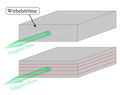
Eddy currents with unlayered and layered (laminated) core structure

Windings
arrangement
The windings of a power transformer are arranged concentrically as cylinder windings or as disc windings one above the other. For example, if a transformer with cylinder winding has three voltage systems (high voltage, low voltage, tertiary voltage), three windings (high voltage winding, low voltage winding, tertiary winding) are arranged concentrically one above the other along a common core leg for each phase. In the case of disc windings, the windings of the voltage systems are divided into several parts and nested, i.e. arranged alternately (e.g. OS / US / OS / US etc.) one above the other. In the case of cylinder windings, one assigns to applications such as B. Mains transformers, the windings of a voltage system with lower voltage because of the more favorable insulation coordination on the core. Because of the better accessibility, the winding parts that are connected to the tap changer are usually on the outside. In industrial applications, such as furnace and converter transformers, the high-voltage winding block is usually arranged on the core so that the low-voltage winding can be arranged on the outside. On the one hand, this is necessary in order to be able to connect the massive winding leads to the equally massive undervoltage lead. On the other hand, it has a beneficial effect on the cooling of the undervoltage block. For reasons of symmetry, the windings of the voltage systems can also have a double-concentric structure. That is, the low-voltage winding block is divided into two parts and the high-voltage winding block is located between the two parts. Disk windings are also used for the same reason. With these nested winding systems, low short-circuit voltages can be achieved. Or, in certain cases, the desired short-circuit voltages can only be achieved with winding systems arranged in a double concentric manner or nested in disks.
species

Windings can be designed as layer windings, in which the turns of the winding are wound like a screw over the winding height. Several layers can be arranged concentrically one above the other and connected in series in order to achieve the required number of turns. The layer tension, which builds up over the individual windings and their winding tension, drops across a layer. Since the neighboring layers must be insulated against this voltage, layer windings are mostly only used at low and medium voltage levels, sometimes also for high voltage. They are also used in high-current applications and are arranged as parallel groups with the same voltage per group and connected in parallel to the down conductor. Coil windings are used for higher voltages, but also for high current applications. In the case of coil windings, individual coils are wound with turns on top of one another. The coils have the same number of turns, are arranged one above the other along the winding height and are alternately connected to one another. Because of the lower number of turns, there is a lower voltage between the disks than between two layers. In high-current applications, the coils are wound axially and radially in parallel with many flat wires.

Basic sectional view of a layer winding

Basic sectional view of a coil winding

Basic sectional view of a high-current transformer with layer winding (e.g. active converter part without control)


Winding material
A distinction is made between copper and aluminum windings. For low powers and currents, foil windings are used as layer windings up to the medium voltage level. The individual turns are wound on top of each other so that there is only a low layer tension. For larger capacities, flat wires are used that can be wound axially and radially in parallel in order to increase the effective cross-section. For very high outputs, many small individual conductors isolated from one another are used, which are combined into a flexible twisted conductor like a Roebel bar . In this way, very large cross-sections can be realized. So-called twisted wires are only mechanically stabilized with a fine network. Additional losses are induced in a solid conductor by the field of the winding. With twisted conductors, the additional losses are lower because of the large number of individual conductors.
isolation
The winding wires are wrapped in an oil-impregnated paper layer ( crepe paper ), or held by pressboard structures at a distance from one another , depending on the requirements for insulation coordination . Because of the catalytic influence of copper on the formation of acids and sludge in the insulating oil, only painted copper parts are generally used. Even copper parts that are isolated by distance or paper, for example, have a layer of lacquer. Other insulation materials and load-bearing structures in a power transformer consist, for example, of oil-soaked pressboard , hard paper or hard tissue . High-current windings of furnace and converter transformers, between the individual windings of which only low voltages occur, often have winding wires that are only insulated with a thin layer of lacquer. These winding wires are separated from one another by means of shims. The supplements are intended to prevent the enamel insulation damaged by friction of the wires together and so turns shorts can occur. In addition, cooling channels are formed by the inserts, thus ensuring improved cooling. The oil-impregnation of the mentioned insulation parts of oil-filled transformers only takes place after production when the transformer is filled with oil. The windings of high-current transformers, especially of furnace transformers, are exposed to strong forces. This is due to the highly dynamic processes that take place in electric arc furnaces, for example . These processes lead to asymmetrical operating states, some of which are close to short-circuit operation. Therefore, the windings of industrial transformers must be designed to be extremely robust.
Influence of winding voltage on short-circuit voltage and losses
The short-circuit impedance and thus the short-circuit voltage is influenced by the height, the width and the diameter of the windings as well as by their distance from one another (for example the main scattering channel between the OS and US systems). The height, width and diameter of the windings are influenced, among other things, by the core cross-section, the number of turns to be accommodated, the cross-sections of the winding wires, the insulation coordination with insulation thicknesses and distances, the cooling design with radial and axial cooling channels, and the design for the short-circuit forces with shims and support cylinders.
The given rated voltages on the high and low voltage side result in a certain number of turns for the winding systems with a selected winding voltage. The core cross-section is also a function of the winding voltage. According to the main transformer equation, the number of turns decreases with increasing winding voltage. As the winding voltage increases, the short-circuit losses decrease because the number of turns and thus the length of the conductors on the winding circumference decreases with the same rated current and conductor cross-section. With the winding voltage, the core induction and thus the no-load losses increase with a constant core cross-section .
The challenge is to find the optimal winding voltage in order to achieve the desired rated data, such as the short-circuit voltage or maximum permissible noise, with the optimal use of materials and with low losses. The manufacturing limits, such as minimum and maximum winding diameters or their dimensions, of the manufacturing plant must be observed. The level of induction also influences the core noises , which become stronger with increasing induction. Noise is an important design criterion with regard to hearing protection for system operators or for transformers that are operated near inhabited areas.
Derivatives
The winding ends are led out of the windings on the high and low voltage side and connected to the so-called down conductor for interconnection (e.g. in delta or star connection ). In the case of standard transformers, a distinction is made between the high and low voltage discharge and the control discharge. The high or low voltage discharge connects the windings depending on the desired interconnection with one another and with the corresponding bushings. The control derivation is used to connect the coarse and fine steps with the step switch or the switching position with the diverter. Different types of on-load tap changers and diverter switches are used depending on different sizes of the electrical design of a transformer. These variables are, for example, rated current and voltage, switching capacity or step voltage. It may also be necessary to use several tap changers and tap changers if certain values, such as the rated current, are too high. In standard transformers, round copper rods and cables are used for the discharge, and rails and copper tubes are used for higher currents. In the case of special high-current transformers, the undervoltage discharge is implemented with very massive copper bars or even plates. Converter transformers can have transducers in the discharge of the low voltage side for current or voltage regulation . Depending on the requirements, the winding ends are connected to the leads using press or crimping , screw and brazed connections. The constructions of the copper bars or plates themselves can consist of individual parts that are connected by welding .
The cross-sections of the conductors influence the amount of additional losses that are added to the short-circuit losses . Leads contribute to the short circuit impedance. Discharges from high-current transformers have a particularly great influence. This influence can be minimized by appropriate cable routing. It is possible to arrange the conductors in such a way that the fields of the current-carrying parts of the individual phases or of a forward and return conductor compensate each other, which helps to minimize the additional impedance. After the active part has been manufactured, it is dried in an oven process and then placed in the kettle. Depending on the manufacturing technology used, the vessel cover can already be connected to the active part or the active part is separate from the cover and the cover is placed on the vessel after the active part has been inserted.

An active part is connected to the tap changer via the rule derivation during production

Control derivation with three single-phase step switches

Low voltage side of the active part of an arc furnace transformer for use in an open circuit

Boiler and attachments

The boiler, also known as the tank, is a steel structure that contains the active part and is closed by a lid. The magnetic fields of the windings and leads cause eddy current losses in the steel parts. In order to limit this and to prevent the steel parts from heating up, it is possible to shield the steel parts from the magnetic fields with aluminum or electrical sheets. There are also numerous add-on parts, such as the pipes of the expansion tank or the domes of the penetrations. Finally, the boiler is filled with oil under vacuum . The transformer oil with which the transformer is filled is usually mineral oil , but occasionally vegetable oils and synthetic organic esters are also used. Control cabinets for the secondary technology of the transformer and for the motor drive (s) of switches and converters can be located on the boiler. Secondary technology includes actuators (e.g. pumps or fans of the cooling system, remote-controlled slides) and sensors (e.g. temperature and oil pressure measurement) as well as control and regulation units (e.g. PLC , VPS for controlling or regulating the cooling system ) of the transformer.

Machine transformer with a tank suitable for railroad profiles and attachments (bridge center piece) for transport in the Schnabel trolley

Transformer with corrugated wall boiler

Transformer with tank suitable for railway profiles and cable connection boxes


Bushings
On the lid or on the sides, the drainage lines are led out of the boiler through bushings . The design of the bushings depends on the rated voltage and the associated test voltage levels as well as the rated current. The design of the bushings is conditional on the voltage levels striking distance affected. As the rated voltage rises, the length of the bushings increases in order to guarantee the distance to adjacent outer conductors and earthed parts. The required minimum distances to neighboring outer conductors and earthed parts are defined in DIN EN 60076-3, for example. In addition to the insulator, the bushings have current-carrying conductors or bolts. Their dimensioning depends on the rated current of the bushing and the associated maximum permissible current density in the conductor. High-current bushings of furnace transformers, which are dimensioned for several kA and low voltages, are designed as copper swords. In the case of particularly high current loads, pipe penetrations that are cooled with water are used.
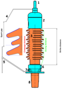
Schematic representation of a 52 kV bushing
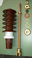
Individual parts of a DIN bushing (including porcelain insulator and copper bolt with connector)

Installation of a 400 kV high voltage bushing
Low and medium voltage bushings


Cooling system
Cooling systems are required to dissipate the power loss. A distinction is made between different cooling variants and operating modes . The oil flows freely or forced by pumps into the cooling system, in which the heat is released into the environment. ONAN cooling systems are used, for example, in which the oil flows into radiators and the heat is released into the environment through free (natural) convection . The cooling performance of a radiator cooling system can be improved by using fans to dissipate heat (ONAF). By adding oil pumps to force the oil flow, the cooling capacity can be further increased (OFAF). In order to be able to dissipate even higher power losses, water cooling systems are used instead of radiators. For example, cooling systems with oil pumps and water-cooled heat exchangers are used for furnace transformers (OFWF / ODWF). The cooling system is either located on the boiler or set up separately. The electrical power supplied to the pumps or fans is part of the system's own electrical consumption. The O indicates the use of mineral oil . A K instead of an O indicates that a non-mineral oil such as B. silicone oil , natural or synthetic ester , is used.
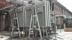
Radiators and fans of an ONAN / ONAF cooling system, installed separately in a radiator battery

Transformer with oil / air heat exchangers and fans (OFAF or ODAF)

Transformer with presumably forced or directed ester oil cooling, radiators and fans (KFAF or KDAF)

Dry type transformers
Dry-type transformers are used where oil-filled transformers cannot be used or can only be used with complex safety measures due to the fire load and water hazard associated with the oil . Like oil-filled power transformers, dry-type transformers have a core made of laminated electrical steel. The windings are designed as wire or tape windings with solid, dry insulating materials. Frequently, the windings, especially the high-voltage side, in casting resin is poured (cast resin). Since cast resin transformers are less able to dissipate the heat loss, they are limited to outputs of up to 40 MVA; larger units are equipped with additional fans. They are used in the field of medium-voltage networks, primarily as distribution transformers to supply the low-voltage networks of large building complexes and in industrial and wind power plants .
exams
According to the applicable standards, power transformers must be tested after they have been manufactured. The manufacturing plants usually have their own test field. The abbreviation FAT for English Factory Acceptance Test is also common in the German-speaking world for this factory acceptance test . The applicable standards can, among other things, stipulate in what condition and to what extent the different types of transformers are to be tested. In DIN EN 60076-1, for example, a distinction is made between routine tests, type tests and special tests. The condition of the transformer during the test and its scope can generally be agreed between the supplier and the customer, deviating from the standard. In this way, special tests can be agreed that go beyond the requirements of a standard. According to DIN EN 60076-1, a transformer must be fully equipped for testing, for example. If this is not possible, for example because there is insufficient space in the test field, partial assembly can be agreed. The sequence of the tests is not prescribed and can be freely chosen or freely agreed.
Guaranteed values

During the tests, compliance with the previously agreed guarantee values, such as short-circuit and no-load losses, the short-circuit voltage or the sound level, is checked. As purely technical guidelines, the standards allow technical tolerances for guaranteed values. Loss values may be exceeded by a certain value or the short-circuit voltage may deviate positively or negatively. Commercial agreements can be made to prevent manufacturers from deliberately counting on the tolerances, i.e. deliberately exceeding or falling short of guaranteed values, for example to save material. It is customary to agree penalties in the event that loss values are exceeded. However, a bonus can also be agreed if the loss values are not reached. If technical tolerances are exceeded or undercut, the manufacturer has the right to make improvements. This also applies to failing other exams. In the event of further non-fulfillment, the customer has the right to reject Any further liability claims by the customer are heavily dependent on the content of the contract and the applicable law.
Routine tests
Routine tests for all transformers
Routine tests must be carried out for every power transformer manufactured. It carried out measurements of winding resistances , translating and phase position, the short-circuit impedance and short-circuit losses of no-load losses and no-load current. In addition, voltage tests are prescribed, which are described in a separate part of DIN EN 60076 (DIN EN 60076-3). If step switches are available, they must be installed on the transformer and, as stipulated in the standard, operational processes must be carried out with them without errors. A leak test and a pressure test are carried out on liquid-filled transformers. With built-in converters, the gear ratios and polarity are checked.
Additional routine tests

Additional routine tests are carried out on transformers with rated voltages greater than or equal to 72.5 kV. However, these tests can also be agreed for transformers with lower voltage. The capacities and the DC resistance of the winding to earth and between the windings are determined or measured. In order to record the state of the insulation system, the loss factor (tan ẟ) of the capacities of the system is measured. It should be noted here that hardly any standard specifies guide values for the loss factor. There are manufacturers of test systems who provide recommendations for reference values for evaluation. These values usually relate to standard network and distribution transformers. In the case of industrial and special transformers that have complex winding, discharge and feed-through systems or several active parts, the application of the generally given guide values is questionable. The dissolved gases in the dielectric liquid are also measured in each individual and separate liquid space. The diverter switch compartment of the tap changer is excluded from this. In addition, the no-load losses and the no-load current are measured at different field strengths in the core, i.e. different voltages. Some standards specify at least 90% and 110% of the rated voltage here.
Type tests
Type tests are used to verify and validate a transformer design. For this reason, these tests are only required for one piece in a series. If there is no series but only a prototype, this must be checked. A temperature rise measurement must be carried out. In the vast majority of cases, factory test fields do not have the connected load to test a power transformer in rated operation. Therefore, they are short-circuited and checked for rated currents or currents agreed with the customer. Among other things, liquid temperatures, winding temperatures and their hot spots are measured or indirectly determined. Unless otherwise agreed, certain voltage tests are only carried out as type tests. A lightning impulse voltage test stresses the insulation system during the test and can weaken it in the process. Guaranteed values can be agreed for different sound levels, for example with different types of cooling, and these are checked. Sound levels are given in either sound power or sound pressure with reference to a distance. The type tests also include the measurement of no-load losses and no-load current at different voltages, which is not included in the routine tests for transformers with a rated voltage of less than 72.5 kV. In addition, the power consumed by fans and liquid pumps is measured. In the case of transformers that fall under the Ecodesign Directive (Regulation (EU) No. 548/2014 of the European Commission of May 21, 2014), the internal electrical consumption is also assessed and is relevant for acceptance there.
Special tests

The special tests are, on the one hand, tests that can be specially agreed. On the other hand, there are routine and type tests that may not be required for a certain type of transformer and that can also be agreed as special tests. Special dielectric tests can be agreed. The winding hot point overtemperature can be measured, which requires a heat measurement and a measuring method for direct recording of measured values. The determination of the capacities of the windings to earth and between the windings and the measurement of the dissipation factor (tan ẟ) of the capacitance of the insulation system also fall under special tests. The determination of the transmission behavior of transient voltages, the measurement of the zero impedance (s) of three-phase transformers and the measurement of the DC insulation resistance of the windings to earth and between the windings can be agreed. A special test is the test of the short-circuit strength of a transformer. In this test, the transformer is short-circuited and the short-circuit is fed by a network that can provide the actual or an agreed short-circuit power. This test places considerable stress on the winding systems. It is not uncommon for a transformer from the series to be selected by the customer specifically for this test and then not used or only kept as a reserve. A test, which is often referred to as the transformer's fingerprint, and the procedure of which must be agreed between the manufacturer and the customer, is the measurement of the frequency response. The abbreviation FRA for English Frequency Response Analysis is also used in German-speaking countries. The measurement of the dissolved gas in the dielectric liquid can be agreed several times at different times during the FAT. For example, the measurement of the dissolved gases could be carried out before and after the heat measurement. A series of vacuum or overpressure tests of the liquid-filled transformer, the examination of the external coating and a mechanical test or assessment of the boiler with regard to its transportability can be agreed. The determination of the transport mass or the measurement of the transport mass for transformers with a low rated power can be agreed.
type label

The nameplate of a power transformer contains the necessary information for transport, operation and maintenance:
- Rated output : maximum continuous output for which the transformer is electrically and mechanically designed and which does not lead to premature aging or damage; specified as apparent power in the unit VA
- Short-circuit voltage: Voltage on the high-voltage side that is necessary so that the rated current flows in the short-circuited low-voltage side; given in percent of the rated voltage
- Rated voltage : RMS voltage level of the high / low voltage side and, if applicable, of the tertiary systems, according to which the insulation coordination is carried out in the electrical design
- Rated frequency
- Insulation level: rms values of the voltage level that were used for insulation coordination depending on the rated voltage
- Rated current: rms values of the currents for which all cross-sections of current-carrying components, such as B. winding wires, leads, electrical contacts or bushings are designed
- maximum short circuit duration : specified in seconds
- Construction year
- Vector group : indicates the coupling with respect to the vector image with the phase shift of high voltage and low voltage
- Type of cooling : with water cooling, the required cooling water flow rate is specified
- Sound power or sound pressure: sound emissions during operation
- Insulation fluid for oil-filled transformers
- Transformer data: Information on the type of current transformer and, if applicable, their transformation ratios
- total weight
- Oil weight
transport
Depending on their power and type, power transformers have a mass of several tens of tons to several hundred tons and the associated dimensions. The transportability in the production areas of the transformer plant and on the available transport routes is a factor that limits the maximum size of power transformers. Transport by heavy load transport , unusual consignments by rail or transport by water is often necessary.

Transport on a low loader

Rail transport by means of a lifting wagon

Operations management, monitoring and maintenance
Operational management
Power transformers are subject to different loads depending on their type, use and operational management. There are applications in which a transformer is operated far below its rated output. For example, some network transformers run in parallel with other transformers and power reserves are held, which is why the individual transformer is rarely fully utilized. Other applications require that a transformer is almost always in full load operation. Examples of this are industrial applications where the production capacity depends on the performance of the transformer. In addition, the relevant standards such as DIN IEC (not EN) 60076-7 stipulate that transformers must be overload-capable under certain circumstances, which is why operation in overload is also conceivable. The aging of the transformer depends on the operational management and the associated load. Among other things, the insulation system of the windings ages due to thermal stress. The higher the electrical load, the higher the thermal load and the faster a transformer ages. The consequence of winding insulation at the end of its service life is damage and thus the end of the transformer's service life. In addition, external influences are responsible for the aging of a transformer. There are applications in which transformers are not exposed to any or very little environmental conditions. Transformers can be housed in buildings or partially enclosed. Other transformers must be able to withstand extreme environmental conditions. Transformers on offshore platforms or in industrial plants can be exposed to a highly corrosive environment. Other transformers have to withstand extreme cold or heat or are submerged in the ocean to form electricity networks there.

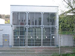
Transformers in a building
Enclosed transformer
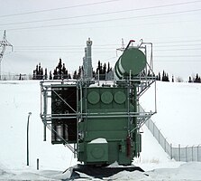
Transformer installed outdoors at low temperatures

Transformer in the middle of a substation


Errors and their consequences
The distribution of the failure probability of a transformer corresponds to the typical bathtub curve . In the early days, transformers fail mainly due to design or manufacturing errors. An error in the operational management concept is also conceivable. Once this phase is over, there is a period of time during which the transformer usually does its job without being noticed. An operator cannot prevent the aging of his transformers, but he can influence them through the way they are operated. A mains transformer operated under partial load can work unobtrusively for several decades. A furnace transformer in full or partial overload can show abnormalities after just a few years.
As already mentioned at the beginning, the thermal load is a strong criterion for the service life of the insulation system and thus the transformer. IEC (not EN) 60076-7 describes the relative service life consumption and the service life of the transformer insulation and illustrates the strong relationship between the thermal load and the life expectancy of a transformer.

Common errors in the core area are mechanical deformations, open core earthing and short-circuited core sheets. In the case of windings, interturn and winding shorts, short circuits of the individual conductors in twisted conductors, earth faults, mechanical deformations, contact problems and open connections occur. The solid insulation and the insulating liquid can contain excessive moisture. The insulating liquid can also be contaminated. Faults in the insulation system can result in partial discharges. Contact problems can occur on tap changers and in the wiring. Current transformers can have winding shorts. The insulation systems of bushings can be faulty.
Errors can lead to reduced operational safety and restrict operational management. The consequence of this can be danger to life and limb as well as to property. In the area of the networks, individual networks can fail. In the industrial sector, high production losses can occur if a replacement transformer has to be installed or a new transformer has to be procured.
monitoring

Power transformers are therefore continuously monitored with extensive safety devices. For example, Buchholz relays , differential protection , pressure monitoring of cable connection boxes and boilers, oil level monitoring and permanent monitoring of the gas in the insulating liquid are used.
Diagnostic procedures for transformers

There are basically two ways of detecting possible damage to a power transformer: On the one hand, a sample of the transformer oil can be taken and then examined using chemical and physical methods. On the other hand, the electrical properties of the transformer can be measured. In the case of power transformers, in addition to oil analysis, which can only record a few individual points in time due to its complexity (removal of the oil on site, transport, chemical analysis in the laboratory), transformer monitoring is becoming more and more popular . The automatically determinable variables are constantly recorded, recorded and immediately transmitted to the operator and / or manufacturer. The operator can then carry out or plan in advance the maintenance based on the automatically determined data.
Oil analysis
By examining the transformer oil, various conclusions can be drawn about the degree of aging and possible hazards during operation as well as necessary maintenance measures (such as drying the oil). The analysis of the transformer oil is usually done in three separate processes. In addition to a chemical examination of the liquid components of the oil (CHEM), an examination of the gases dissolved in the oil (DGA) is carried out, in addition, the furans that may result from the decomposition of the oil are specifically searched for (FUR).
On the oil itself, among other things, there is a color index for classification from "0" (colorless, new) to "6" (dark brown), furthermore the breakdown voltage , the water content (determined for example by Karl Fischer titration ) as well as the water saturation between dry (with <6 ppm water in the oil) to extremely moist (with> 30 ppm water in the oil) and the neutralization number or the acid content are interesting. The latter provides information about aging products in the transformer, for example due to the breakdown of the cellulose from the layer insulation of the windings. The chemical analysis also determines the purity of the oil, the saponification number , the loss factor at 50 Hz, the density at 20 ° C, the refractive index , the interfacial tension, the particle and inhibitor content.
Conclusions about previous discharges and overheating in the transformer can be drawn from the analysis of the gases dissolved in the oil (Dissolved Gas Analysis DGA), since the reaction products were present as gases. In this investigation, the content of the gases hydrogen, methane, ethane, ethylene, acetylene, propane, propylene, carbon monoxide, carbon dioxide, oxygen and nitrogen is usually determined.
The furan analysis usually searches for 5-hydroxymethyl-2-furfural (5-HMF), 2-furfuryl alcohol (2-FOL), 2-furfural (2-FAL), 2-acetylfuran (2-ACF) and 5-methyl -2-furfural (5-MEF) wanted. Since these are decomposition products of the paper insulation, one can draw a conclusion about the condition of the paper insulation from the amount of furfurols.
In addition to the classic chemical analysis of the oil, conclusions can also be drawn about the properties of the insulation materials (oil, paper, pressboard) of a transformer using dielectric spectroscopy . Of particular interest are the conductivity of the oil (dielectric strength) and the moisture content of the oil and paper or pressboard.
Electrical procedures
Further diagnostic approaches consist of electrical examinations. To be mentioned here are the measurement of the static resistance of the load switch contacts and the windings as well as the measurement of the capacitance by determining the loss factor and the conductivity at certain frequencies. From this, partial breakdowns as well as oil inclusions, cracks and changes in the geometry from winding to winding or to the transformer tank can be determined in bushings. Furthermore, the transmission function of the transformer can also be determined with the aid of a signal analysis (Frequency Response Analysis FRA); this also provides information on changes in the geometry of the transformer installations.
maintenance

According to relevant standards and regulations, revisions and maintenance of electrical systems are prescribed. Examples of standards and regulations of this type are BGV A1 and BGV A3 as well as DIN 57 105-1 and VDE 0105-1. The minimum for the maintenance effort of power transformers is defined by the manufacturer, who specifies the maintenance intervals for certain components of the transformer.
Step switches are a sensitive individual component of the transformer. Maintenance intervals are given for them by their manufacturers after certain operating times or switching cycles. In order to carry out a tap changer inspection, the transformer must be disconnected from the mains. A simultaneous revision is therefore advisable in connection with an inspection.
Repairs and retrofits
Repair options are offered by manufacturers themselves, but also manufacturer-independent. The offers refer to all components of the transformer. External repairs such as sealing measures in the event of leaks on the boiler, reconditioning the corrosion protection or the replacement of accessories are offered. However, there is also scope for work on internal components, such as maintenance of tap changers or oil treatment. In addition, extensions to the secondary technology are offered. Monitoring systems or systems for permanent degassing can be retrofitted.
The service life of a transformer can be increased by retrofitting, i.e. refurbishing transformer components. For economic reasons, attempts are being made to reuse many components of the transformer. For example, it is possible to recondition the core and the tank of a transformer and only re-manufacture the windings. This approach makes economic sense if, for example, the measure causes costs that are far below the new price of a transformer with the same rated data and a significant extension of the service life is achieved.
Parallel connection
Sometimes instead of using one large power transformer, two or more smaller ones are connected in parallel, e.g. B. if a single large transformer would be too difficult to transport to the installation site or you can use standard sizes instead of a special size. Often, considerations relating to failure safety are also decisive. If one of two transformers fails, the connected line can continue to operate at least with reduced power. If only a small amount of power is required at certain times anyway, one of the two transformers can be switched off completely, eliminating its losses through internal consumption (oil circulation, cooling fans). In addition, in the event of a later expansion of the transmission capacity in order to safeguard the investments made previously, it can make sense not to replace the transformer used previously, but only to add another one.
Power transformers can only be connected in parallel if the voltages on the high and low voltage side and the vector groups match. Otherwise high equalizing currents would flow between the transformers, which would damage them. The rated powers of the transformers should not differ from each other by more than three times. If these conditions are met, the short-circuit voltage must also approximately match. The short-circuit voltage indicates the voltage on the primary side at which the nominal current flows on the short-circuited secondary side. It is a measure of how much the secondary voltage changes under load. If you connect two transformers with different short-circuit voltages, the one with the lower short-circuit voltage will be overloaded in certain operating states.
900 kVA are to be transmitted. There is a 400 kVA transformer with a relative short circuit voltage of 8% and a 600 kVA transformer with a relative short circuit voltage of 6%. How is the power actually divided between the two transformers?


Applicable standards and regulations
There are various standards and regulations that apply to power transformers. In Germany and Europe, power transformers are generally designed and operated according to EN or IEC 60076, in the USA for example according to IEEE C57.12, in Canada according to CAN / CSA-C88-M90. There are also various other standards and regulations for special applications, such as power converter transformers.
Examples are:
- DIN EN 60076-1 - Power transformers Part 1: General
- DIN EN 60076-2 - Power transformers Part 2: Excess temperatures for liquid-filled transformers
- DIN EN 60076-3 - Power transformers Part 3: Insulation level, voltage tests and external clearances in air
- DIN EN 60076-4 - Power transformers Part 4: Guideline for lightning and switching impulse voltage testing of power transformers and reactors
- DIN EN 60076-5 - Power transformers Part 5: Short-circuit strength
- DIN EN 60076-6 - Power transformers Part 6: Choke coils
- DIN IEC 60076-7 - Power transformers Part 7: Guide to the loading of oil-filled power transformers
- IEC 60076-8 - Power transformers Part 8: Application guide
- DIN EN 60076-10 - Power transformers Part 10: Determination of the noise level
- DIN EN 60076-11 - Power transformers Part 11: Dry-type transformers
- DIN EN 60076-12 - Power transformers Part 12: Guidelines for the loading of dry-type transformers
- DIN EN 60076-13 - Power transformers Part 13: Self-protected liquid-filled transformers
- DIN EN 60076-14 - Power transformers Part 14: Design and application of liquid-filled power transformers with high-temperature insulating materials
- DIN EN 60076-15 - Power transformers Part 15: Gas-filled power transformers (still in the design phase)
- DIN EN 61378-1 - Converter transformers - Part 1: Transformers for industrial applications
- C57.12.00 - IEEE Standard General Requirements for Liquid-Immersed Distribution, Power, and Regulating Transformers
- CAN / CSA-C88-M90 - Power Transformers and Reactors - Electrical Power Systems and Equipment
Remarks
- ↑ In electrical machines, the active part is the part of the machine in which the magnetic and electrical processes that are important for energy conversion take place. (Source: Hans-Otto Seinsch: Fundamentals of electrical machines and drives. )
literature
- Andreas Küchler: High voltage technology . 2nd Edition. Springer, 2005, ISBN 3-540-21411-9 .
- E. Arnold, JL la Cour: The alternating current technology . Volume Two The Transformers. 2nd Edition. 1923.
- Rodulf Küchler: The transformers. Basics for their calculation and construction. 2nd Edition. 1966.
Individual evidence
- ↑ a b Andreas Küchler: High voltage technology. 2nd edition, Springer 2005.
- ↑ Electric Arc Furnace Transformers ( Memento of the original from March 20, 2013 in the Internet Archive ) Info: The archive link was automatically inserted and not yet checked. Please check the original and archive link according to the instructions and then remove this notice. (PDF; 1.3 MB), technical description of the Tamini Group, requested on January 21, 2012, engl.
- ↑ Alstom (Ed.): Electric Arc Furnace Power transformers up to 360 MVA . S. 1-4 ( PDF ). PDF ( Memento of the original from January 24, 2014 in the Internet Archive ) Info: The archive link was inserted automatically and has not yet been checked. Please check the original and archive link according to the instructions and then remove this notice.
- ^ Robert Durrer, Georg Volkert: Metallurgie der Ferolalierungen 2nd edition, Springer 2013.
- ↑ Andreas Küchler: High voltage technology basics - technology - applications . 3rd, revised edition. Springer Science & Business Media, Heidelberg, Dordrecht, London, New York 2009, ISBN 978-3-540-78412-8 , pp. 608 .
- ^ OTF - Electric arc and ladle furnace. SEA Società Elettromeccanica Arzignanese SpA, 2018, accessed on February 13, 2020 .
- ↑ Animation for the construction of a power converter power transformer (YouTube)
- ↑ University of Rostock (ed.): 5. Transformer . S. 1–23 ( PDF 1.23 MB ). PDF 1.23 MB ( Memento of the original from April 24, 2014 in the Internet Archive ) Info: The archive link was inserted automatically and has not yet been checked. Please check the original and archive link according to the instructions and then remove this notice.
- ↑ Diploma thesis Martin Neuwersch: "Status of diagnostics in transformers" , Institute for High Voltage Technology and System Management Graz University of Technology, 2.2.3 Winding structure , PDF accessed on March 10, 2019
- ↑ ASTA twisted conductors and flat wires , accessed on March 10, 2019
- ↑ ttf - Advantages of aluminum tape winding , accessed on March 10, 2019
- ↑ Dry-type transformers SGB-SMIT , PDF accessed on March 10, 2019
- ↑ DIN EN 60076-1 - Power transformers Part 1: General
- ↑ Siemens Energy - Power Transformers
- ↑ European Patent Office (Ed.): EP 0078366 A2 - Capacitor bushing for electrical high-voltage devices . ( [1] ).
- ↑ ABB Power Products (Ed.): High-voltage bushings . ( PDF ). PDF ( Memento of the original from April 28, 2014 in the Internet Archive ) Info: The archive link was inserted automatically and has not yet been checked. Please check the original and archive link according to the instructions and then remove this notice.
- ↑ GEA transformer oil air cooler , accessed on April 19, 2014
- ^ Electrical Engineering - Online Electrical Engineering Study Site , accessed April 19, 2014
- ↑ Siemens builds the most powerful cast resin transformer in the world. (No longer available online.) In: TGA - Technical building equipment. WEKA-Verlag Gesellschaft mbH, November 13, 2007, archived from the original on January 6, 2014 ; accessed on January 6, 2014 . Info: The archive link was inserted automatically and has not yet been checked. Please check the original and archive link according to the instructions and then remove this notice.
- ↑ OMICRON - Dissipation factor / power factor measurement (Tan Delta) on instrument transformers , accessed on March 11, 2019
- ↑ Siemens power transformers , accessed on March 12, 2019
- ↑ ABB power transformers , accessed March 12, 2019
- ↑ Siemens industrial transformers
- ↑ Special application transformers ABB Special application transformers , accessed March 12, 2019
- ^ Niederreiter "Services for Transformers " , accessed on March 12, 2019
- ↑ ABB "Fit mit 50" , PDF accessed on March 12, 2019
- ↑ OMICRON testing and diagnosis of power transformers , PDF accessed on March 12, 2019
- ↑ IEC60422 Mineral insulating oils in electrical equipment - Supervision and maintenance guidance
- ↑ DIN ISO 2049: Mineral oil products - Determination of color (ASTM scale)
- ↑ DIN EN 60156: Insulating liquids - Determination of the breakdown voltage at mains frequency - Test method
- ↑ DIN 51777 testing of mineral oil hydrocarbons and solvents; Determination of the water content according to Karl Fischer
- ↑ DIN EN 62021-1 Insulating liquids - Determination of acid content - Part 1: Automatic potentiometric titration
- ↑ VDE 0370: insulating oils
- ↑ DIN 515591: Testing of mineral oils - determination of the saponification number
- ↑ DIN EN 60247: Insulating liquids - measurement of the permittivity number, the dielectric loss factor (tan d) and the specific direct current resistance
- ↑ DIN 51757: Testing of mineral oils and related substances - determination of density
- ↑ DIN 51423: Testing of mineral oils - measurement of the relative refractive index
- ↑ NF ISO 6295: Petroleum products - Mineral oils - Determination of the interfacial tension of oil against water - Ring method
- ↑ DIN EN 60970: Insulating liquids method for determining the number and sizes of particles
- ↑ DIN EN 60666: Detection and determination of specified additives in insulating liquids based on mineral oil
- ↑ Maik Koch: Reliable Moisture Determination in Power Transformers. Series of publications by the Institute for Energy Transmission and High Voltage Technology at the University of Stuttgart, Volume 1 - 2008, Sierke Verlag.
- ↑ K. Feser: The transfer function method for detection of winding displacements on power transformers after transport, short circuit or 30 years of service. CIGRÉ Session 2000. Paper: 12 / 33-04
- ↑ Maschinenfabrik Reinhausen "Reliable for life." , accessed on March 12, 2019
- ↑ Maschinenfabrik Reinhausen "SERVICE AM TRANSFORMATOR" , PDF accessed on March 12, 2019
- ^ ARS Altmann , accessed on March 12, 2019
- ↑ ABB Transformers "Transformer Remanufacturing & Engineering Services - TRES " , PDF accessed on March 12, 2019