Edward Dean Adams Power Plant
| Edward Dean Adams Power Plant | ||
|---|---|---|
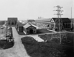
| Photo from 1941. The only remaining building is the transformer house in the front left of the picture. | ||
| location | ||
|
|
||
| Coordinates | 43 ° 4 '54 " N , 79 ° 2' 34" W | |
| country |
|
|
| Waters | Niagara River | |
| power plant | ||
| owner | Niagara Falls Power Company | |
| Start of planning | 1886 | |
| Start of operation | August 26, 1895 | |
| Shutdown | 1961 | |
| technology | ||
| Bottleneck performance | 78.3 MW megawatts | |
| Average height of fall |
41 m | |
| Turbines | 21 Francis turbines | |
| Generators | 21 alternators | |
| Others | ||
The Edward Dean Adams power plant ( English Edward Dean Adams Power Plant or English Adams Hydroelectric Generating Plant ) was a hydroelectric power plant in Niagara Falls in the state of New York in the United States . The power plant, which went into operation in 1895, was the first large-scale power plant to generate alternating current . In 1904 the installed capacity of the power plant reached 78.3 MW (105,000 PS). In the ranking of the largest power plants, it replaced the Deptford power plant in England, which went into operation in 1891 .
The operation of the Edward Dean Adams Power Plant was discontinued in 1961 after the new, more powerful Robert Moses Niagara power plant went into operation at the same location .
history
The use of water power at Niagara Falls began around 1725 with a sawmill on the rapids above the falls for lumber for Fort Niagara. More mills followed, until state reservations were set up here on the rapids. In the 1870s, the Hydraulic Canal started operating. This factory canal supplied several mills , sawmills and pulp mills with water, which was used to drive turbines . The power transmission from the turbines to the machines was still purely mechanical.
In 1882 the first electricity supplying power station went into operation at Niagara Falls. The system was operated with water from the Hydraulic Canal and was used exclusively to generate direct current for lighting purposes .
In 1886, Thomas Evershed suggested the construction of a four-kilometer-long tunnel under the city that would take the underwater from industrial plants that would be set up along the river bank. The Niagara River Hydraulic Tunnel Power & Sewer Company was founded to implement the project , but the project failed due to the lack of funding.
In 1899, the financier Edward Dean Adams , after whom the power plant is named, took over the Niagara River Hydraulic Tunnel Power & Sewer Company and formed the Niagara Falls Power Company from it . The subsidiary Cataract Construction Corporation was founded in New Jersey to build, finance and operate the facility . Your task was to plan, finance and build the project. Adams managed to attract well-known donors to the company, such as JP Morgan , Morris Ketchum Jesup , John Jacob Astor IV and the Vanderbilt family .
Adams planned from the beginning to transport the generated energy to other cities such as Buffalo, 30 km away , but first a suitable technology had to be found for the transport of the energy. The electrical engineering was still in its infancy and electric power grids were not yet established. The most suitable method for the transport and distribution of electrical energy should therefore be sought by the International Niagara Commission based in London. The chairman of the commission was Lord Kelvin , the members were English engineer William Unwin, Coleman Sellers II from the Stevens Institute of Technology , Eleuthère Mascart from France and Théodore Turrettini , electrical engineer from Switzerland. She investigated the transmission of energy with already proven systems, such as a pressurized water supply , as it was used in Geneva from 1886 , or a compressed air supply , as it was used in Paris from 1888 . In the field of the still young electrical engineering, the energy transmission with the help of the transport of lead-acid batteries , a direct current network or an alternating current network was investigated.
Regardless of the as yet unsolved problem of energy transport, the construction of the underwater tunnel began in October 1890 and was completed two years later. The turbines were commissioned in 1892. Due to import duties in the USA, they had to be manufactured according to drawings by the Swiss turbine factory Faesch and Piccard at the IP Morris ironworks in Philadelphia . The turbine pit was completed in January 1894.
Cataract Construction Corporation decided to use alternating current for power transmission on May 6, 1893, and ordered the generators from Westinghouse Electric in October 1893 . The decision to use alternating current was based on its successful use for transmission lines in 1890 at a power station at Willamette Falls in Oregon , in 1891 in three-phase transmission Lauffen-Frankfurt and in the Ames Hydroelectric Generating Plant and in 1893 at the World's Columbian Exposition .
The power plant went into operation on August 26, 1895. The first customers were the Pittsburgh Reduction Company , which produced aluminum using the Hall-Héroult process, and the Carborundum Company, which produced silicon carbide as an abrasive . The supply took place via a 2.4 km long concrete cable tunnel called Forbes Subway .
In June 1896, the Cataract Power and Conduit Company was founded, which was a joint subsidiary of the Niagara Falls Power Company and Buffalo General Electric . The company had the task of transferring the electricity from the power station to Buffalo and selling it there. General Electric received the order to build the necessary transformer stations in Niagara Falls and Buffalo, as well as the two 11 kV overhead lines and to deliver the rotating converter sets for the supply of the tram in Buffalo. The plant went into operation on November 15, 1896. The transformers were provided with fuses on the primary and secondary sides , but they could not protect the system from short circuits. Thus, if a short circuit occurred, the entire power plant had to be shut down by switching off the excitation in the generators. Later on, a circuit breaker in the generator busbar enabled either Niagara Falls or Buffalo loads to continue to be powered after the faulty part of the facility was disconnected. Oil switches were later introduced by General Electric, which were able to switch off short circuits.
The first customer in Buffalo was the tram, which required an output of around 1000 hp. The industry did not yet trust the new technology and was therefore reluctant to switch from steam engines to electric motors. The system was therefore in deficit in the first few years. In 1900 a third transmission line was built and the voltage of all transmission lines was increased to 22 kV because consumption in Buffalo rose sharply.
In June 1975, the power station's transformer house was added to the National Register of Historic Places . In May 1983 this building was granted National Historic Landmark status .
Technical description of the system

The generators were installed in two machine houses designed by the renowned architects McKim, Mead, and White , which faced each other at the inlet duct. The turbine pits of the machine houses drained into the underwater tunnels with a horseshoe-shaped cross-section. The tunnel is two kilometers long, 6.4 m high and 5.7 m wide. For its four-layer lining, 16 million bricks were required.
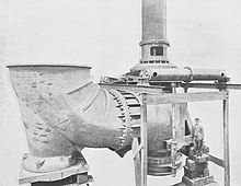
The machine house 1 on the west side of the inlet channel was equipped with ten Fourneyron turbines based on drawings by Faesch and Piccard, each of which drove a 5000 hp generator from Westinghouse Electric. The turbines were arranged without a suction pipe at the bottom of the 6 m wide and 55.5 m deep turbine pit and connected to the associated generator via a vertical shaft. They had two vertically arranged opposing impellers that were loaded from the inside. With this arrangement it was possible to partially compensate the bearing force of the shaft train with the axial pressure on the upper impeller caused by the water. The mechanical turbine governors for the first three turbines came from Faesch and Piccard, those for the rest were electrical and were supplied by William Sellers, Philadelphia. The turbines turned at 250 revolutions per minute, this value was maintained by the controller with a deviation of 2%.
From 1910 to 1913, the Fourneyron turbines in nacelle 1 were replaced by Francis turbines like those used in nacelle 2. The twelve-pole generators from Westinghouse with external rotors generated a two-phase alternating current with a frequency of 25 Hz and a voltage of 2.2 kV.
The machine house 2 on the east side of the inlet channel was equipped with eleven Francis turbines from Escher Wyss , Zurich . Each turbine had an impeller equipped with a suction pipe that was acted upon from the outside. The weight of the shaft assembly was carried on the one hand by a piston exposed to water at the lower end of the shaft assembly and by an axial bearing with oil pressure lubrication at the upper end. Escher Wyss also supplied the servo-hydraulic turbine governors. The 5500 HP generators from General Electric were of two different types: six also had external rotors like those from nacelle 1, the other five had an arrangement with internal rotors , which later prevailed.
Transmission lines to Buffalo
The transformer house was initially equipped with two air-cooled 930 kVA transformers manufactured by General Electric . They converted the two-phase alternating current from the generators with the Scott circuit into three-phase alternating current with a voltage of 11 kV. The transmission line to Buffalo was 35 km long and was constructed very much like a telegraph line . The copper ropes were carried by standing porcelain insulators on cedar poles that were set up 20 meters apart. The last 1200 m were designed as underground cables . The line consisted of two three-phase circuits, each of which was able to transmit all the power required in Buffalo. This ensured an uninterrupted supply. In Buffalo, three 250 kVA transformers were connected in delta , which operated two rotating converter sets for the power supply of the tram catenary . If the transmission line failed, the 550 V direct current required for the tram could also be generated using local direct current generators powered by steam engines. The efficiency of the transmission line including transformers was 79.6%. The lines were Wurts - Role lightning rod protected against surges, but their effectiveness was called into question, since they are the high short-circuit capacity could not cope with the power plant.
The transmission line, built in 1900, was constructed with aluminum cables carried by hanging insulators on steel masts. The masts were 40 m apart. Experience with the first line showed that ice formation on the line was not to be expected in winter, which is why the mast spacing could be chosen to be significantly larger. To supply the second line, ten water-cooled transformers with oil insulation from Westinghouse were installed, each with an output of 1875 kW. The efficiency of this transmission reached 88.4%.
See also
literature
Web links
- Niagara Falls History of Power. In: Niagara Falls Thunder Alley . Rick Berketa, accessed December 29, 2013 .
- Nikola Tesla and George Westinghouse built the first hydro-electric power plant in 1895 in Niagara Falls and started the electrification of the world. Tesla Memorial Society of New York , accessed December 30, 2013 .
Individual evidence
- ↑ Inventory Nomination Form for National Register of Historical Places. (PDF) National Park Service , accessed December 30, 2013 .
- ^ A b c Doris Ward: History of Hydro and Power Plants in the Niagara Region. Rootsweb Ancestry , accessed January 8, 2014 .
- ↑ Michael Krause: How Nikola Tesla invented the 20th century . John Wiley & Sons, 2010, ISBN 978-3-527-50431-2 , pp. 168-169.
- ^ WD Howells, Mark Twain, Prof. Nathaniel S. Shaler, and Others: The Niagara Book . Buffalo 1893, p. 221–225 ( Niagara University Library, PDF - Contribution: WC Johnson, CE (civil engineer), The Hydraulic Canal).
- ^ WD Howells, Mark Twain, Prof. Nathaniel S. Shaler, and Others: The Niagara Book . Buffalo 1893, p. 192–220 ( Niagara University Library, PDF - Contribution: Coleman Sellers, ED, The Utilization of Niagara's Power).
- ^ Business Men's Association of Niagara Falls, NY: The Water-power of the falls of Niagara applied to manufacturing purposes: the hydraulic tunnel of the Niagara Falls Power Company . Business Men's Association of Niagara Falls, 1890, p. 11.
- ↑ a b c d e f g h i Early Electrification of Buffalo. In: Engineering and Technology History Wiki. Retrieved September 30, 2018 .
- ^ A b c d William Irwin: The New Niagara: Tourism, Technology, and the Landscape of Niagara Falls, 1776-1917 . Penn State Press, 1996, ISBN 0-271-04222-2 , pp. 108-.
- ↑ a b c d Edward Dean Adams: Niagara Power . tape 2 . Niagara Falls, NY 1927, LCCN 28-007375 , Transmission System (on- line ).
- ^ Adams Power Plant Transformer House on the National Register Information System. National Park Service , accessed August 19, 2019.
- ↑ Listing of National Historic Landmarks by State: New York. National Park Service , accessed August 19, 2019.
- ↑ Thomas P. Hughes : Networks of Power: Electrification in Western Society, 1880-1930 . Johns Hopkins University Press, Baltimore 1983, ISBN 0-8018-4614-5 , pp. 35-139 (English).


