
Slip path
A slip path (also called D-Weg in the area of the former Deutsche Bundesbahn ; in Austria: "Schutzweg") is the part of the route intended for a train journey that must be secured and kept clear as a protective route behind the destination of the journey for safety reasons . This happens in the event that a train inadvertently does not come to a stop, but "slips" beyond the target signal. For the same reason, a protective route is kept free behind the entrance signals of a train station and behind block signals , which is part of the danger point distance.
Signals that, like pure pre-signals and pre-signal repeaters, can not indicate a stop, generally have no protection route, as they are not a route destination .
Behind main signals different trap points available is, in the case of slip roads of choice slip Because speaking, by the dispatcher , automatically through the automatic route setting or be automatically selected according to the present preferred positions and states of these requirements, driveway elements. While in the German safety philosophy a Durchrutschweg may be dissolved after route set only under restrictive conditions and changed, this principle is the " swinging overlaps " standard in Anglo-Saxon assurance philosophies and part of the operationally flexible backup protection routes . However, all these regulations differ greatly between the various railway systems depending on operational and legal requirements as well as the desired and prescribed level of safety.
background
The slip path is used when one of around one hundred thousand journeys indicates a stop. The causes for this are slipping (reduced coefficient of friction between wheel and rail), braking (at the later start of target point braking) and / or disregard ( disregarding or mixing up signals). The most common cause is braking, for example due to braking that was initiated too late.
According to an evaluation of various statistics, about one in ten to one in a hundred main signals encountered are on hold. A signal indicating a stop occurred in the area of Deutsche Bahn in the years 2009 to 2014 about 0.4 times per million train path kilometers . In Germany, main signals indicating stop were run over 470 times in 2014.
In Germany, only a small part of the slip path is actually used when slipping through. Around 50 percent of the cases only slide up to 10 m, around 90 percent up to 50 m. An exception in the autumn of 2003 was the observed braking distance extensions of several hundred meters in various series 423 to 426 multiple units, which had not been observed in multiple units and were due to various technical inadequacies.
Country-specific regulations
Internationally there is great disagreement about the type of application and the safety benefits of the slip path. In some countries such as B. in the Netherlands there is no slip path at all. In countries where slipways are kept free, there are large differences in the length and type of securing. So z. B. the length be fixed or be dependent on criteria such as the type of signal or the danger point and the permissible speed. Some railways close all switches in the slip path, others only those with sharp traffic, others none at all. Flank protection for the slip path is common with some lanes, but not with others.
| Rules for slip paths for infrastructure operators (status: 1995) | ||||
|---|---|---|---|---|
| Infrastructure operator | Length of the slip path | Closure of the slip path | Flank protection for slip path | comment |
| ÖBB (Austria) | 0 m to 40 km / h 50 m over 40 km / h |
Yes | Yes | |
| NMBS (Belgium) | 0 m to 40 km / h 50 m over 40 km / h 100 m for signals in front of switches |
No | ||
| SBB (Switzerland) | 40 m to 45 km / h 100 m over 45 km / h (up to 165 km / h) |
Yes | No | different regulation for meter gauge railways |
| DB (Germany) | 0 m to 30 km / h 50 m to 40 km / h 100 m to 60 km / h 200 m over 60 km / h |
only pointed turnouts | Yes | The specified lengths are minimum lengths when entering stump tracks with stump track and early stop indicators 40 km / h permitted. Some types of relay and electronic interlockings also seal butt slipped points in the slip path |
| RENFE (Spain) | 50 m | Yes | Yes | |
| SNCF (France) | 0 m | No | 100 m clearance at butt-used points | |
| British Rail (Great Britain) | 46 m to 24 km / h above this, incremental, speed-dependent increase up to 183 m (over 96 km / h) |
Yes | Yes | Pointed turnouts at which a suitable alternative slip path is available are not locked |
| FS (Italy) | 50 m for exit signals on platforms 100 m for other signals |
Slip paths are generally not used if the length of a block section is significantly longer than the length of the train | ||
| CFL (Luxembourg) | 0 m to 60 km / h (for inclines and descents up to 2.5 per thousand) 50 m to 60 km / h (for inclines with more than 2.5 per thousand) 100 to 200 m over 60 km / h |
Yes | Yes | |
| NSB (Norway) | 0 to 400 m | No | no slippage on block signals | |
| NS (Netherlands) | 0 m | No | 200 m for signals in front of important points, moving bridges, etc. a. | |
| BV (Sweden) | 200 m where possible 100 m permissible up to 80 km / h |
Yes | No | no specifications for pointed turnouts, as a rule, no slippage at block signals |
Germany
In the terminology of Deutsche Bahn , the slip path behind entry and block signals is called the danger point distance (safety-related protective section ) because this must always be kept free and is not available for other routes (especially shunting routes). Trips on the open route can always be carried out for safety reasons and without the consent of the following operating point. The slip path behind intermediate and exit signals, on the other hand, is resolved after the train stops in front of the main signal and can be used for other routes.
In Germany, the following slip paths apply to routes ending at intermediate and exit signals:
| Allowable speed |
Required slip path |
|---|---|
| > 60 km / h | 200 m |
| ≤ 60 km / h | 100 m |
| ≤ 40 km / h | 50 m (0 m when entering against the buffer stop) |
| ≤ 30 km / h | 0 m |
Different regulations apply in operation with ETCS Level 2 and automatic line control (see below).
It is possible to plan a route with slip paths of different lengths ( choice slip path ). Depending on the available slip path, the speed must then be signaled down accordingly. If the complete slip path behind the signal is not free, or if a track section or a switch located in the slip path is to be used for another purpose after setting the route, the operator can select a shorter or different slip path when setting the route, provided these are set up. The slip paths of two journeys required at the same time may touch each other. It is not assumed that two trains slip through at the same time. Turnouts located in slip paths are usually only locked if they are slid to a point. On the closure of a truncated berutschten trailable points with drives is omitted, but should still be brought to possibility of registration of a ride in the corresponding position ( control position switches ). Because of the effort required, locking a control switch in the wrong position is not prevented in mechanical interlockings, although the opening of a locked switch leads to massive damage.
The shortening of the danger point distance behind entry signals to 100 m is permissible if a point followed by a sharp point , the speed does not exceed 100 km / h and the incline in this area is not greater than 0 ‰. It should be noted that 200 m behind the entry signal no other danger point may follow on either of the two tracks.
When determining the relevant danger point distance, the relevant longitudinal inclination with the greater of the two following values must also be taken into account:
- the average gradient over a length of 2 km in front of the main signal considered.
- the average inclination from the beginning of the braking distance to the main signal under consideration.
If the decisive incline results in a gradient, the danger point distance is to be increased by 10% per thousandth of a gradient, but to a maximum of 300 m. In the case of decisive gradients, a shortening of 5% per per mille of decisive gradient is possible; the distance to the danger point must not be less than 100 m (on electrified lines) or 50 m otherwise. These principles came into force in 1957.
The term "slip path" can already be found in the "preliminary principles for the flank protection of the tracks on main lines" of the Deutsche Reichsbahn from March 31, 1930 m and generally not exceed 300 m. Under "special conditions" the length could be reduced to less than 100 m "if the operation requires it". At the end of 1955, the German Federal Railroad “to increase the performance of the stations” generally allowed the possibility of entering overtaking tracks at speeds of up to 40 km / h whose exit or intermediate signal was only 50 m away from the danger point.
In track the switchboard slip paths are resolved timed normally. When the section is occupied, a delay time begins which, depending on the length of the target track, is between 32 seconds (300 m) and 78 seconds (800 m). The setting of a further route that coincides with the not yet resolved slip path is not prevented by this. This was particularly important when trains with a traffic stop were not allowed to be signaled through.
All information on the slip path is summarized in a slip path.
Special regulations apply to the S-Bahn in Berlin and Hamburg . A protective route is kept free behind main signals (except platform signals) . In contrast to the slip path, this is precisely matched to the emergency braking path of the train. Behind platform signals, on the other hand, the term “ slip-through path ” is still used, which can be shortened to a length of up to 2 meters under certain conditions to enable a dense train sequence. This is based on the consideration that an arriving train brakes anyway because of the traffic stop and the risk of slipping is significantly lower as a result or this would only take place over a short distance. This regulation becomes problematic when trains are passing through because they do not brake because of a traffic stop. Accordingly, the speed of passage on the affected routes is limited (S-Bahn Berlin: 50 km / h, S-Bahn Hamburg: 40 km / h), with the S-Bahn Hamburg, passage through stations is generally prohibited with a few exceptions.
On the main line of the Munich S-Bahn, which went into operation in 1972, in order to achieve the highest possible performance, cover signals with up to 52 m short slip paths were placed in front of the start of the platform, with up to two speed test sections (GPA) being placed in front of the signal. The establishment of even shorter slip paths, which would have required even more GPA, was dispensed with for reasons of system availability. In the case of exit signals, 10 m was generally considered to be sufficient, since a slip with the occurrence of two “unlikely events” - a collision immediately behind the signal that has stopped train - “does not have to be expected”. Such regulations were also used on the main line of the Stuttgart S-Bahn, which opened in 1976 .
Austria
In Austria, all protective sections behind main signals are referred to as protective routes ; they start at the associated main signal and usually end before the next possible danger point such as a switch . In terms of safety, these protective routes are therefore comparable to the German danger point distances , but are also used for exit signals . As a result, the Austrian security philosophy now differs from the federal German, although both can be traced back to the same origins.
In Austria, protection paths were largely dispensed with due to capacity reasons. The minimum length of protective paths at ÖBB was shortened to 50 meters in the 1980s. According to signal regulation S60, 50 m long protective paths are to be provided in Austria (as of 2020).
Switzerland
In Switzerland, a distinction is made between normal gauge and meter gauge / special gauge for the length of the slip paths . The length of the slip path is determined using a stepped curve in steps of 10 km / h, depending on the entry speed; In the case of meter gauge / special gauge, a distinction is also made as to whether the trains have magnetic rail brakes or not.
Compared to Germany, the slip paths in Switzerland are not only shorter, but also vary significantly more depending on the entry speed. This is advantageous in tight spaces, but can lead to major reconstruction measures if the entry speed is increased.
Czech Republic
There are no slip paths in the SŽDC area . The rigid block section boundaries are already shortly after a signal . Accordingly, a vehicle can be located again shortly after such a signal .
Anglo-Saxon area
In the Anglo-Saxon area, protective routes are referred to as overlap ; the term describes the overlap of the protective path of the main signal behind and the first part of the following block section.
System-specific regulations
ETCS
In the European Train Control System (ETCS), a slip path known as an overlap can be defined. It begins at the end of the driving permit ( End of Authority , abbreviation EOA , target speed 0 km / h, end of the service braking curve ) and ends at the danger point ( supervised location , abbreviation SvL ), the end of the emergency braking curve . Even if there is no slip path, the danger point may be behind the end of the driving permit (EOA). The ETCS specifications explicitly state that the slip path ( overlap ) can support the efficiency of the ETCS braking curve monitoring . If no slip path is planned, ETCS service and emergency braking curves end at a common point. The approach to this point takes place at a very low speed in these cases. As a rule, the associated balise group can not be reached and therefore no new driving license can be accepted for ETCS Level 1 (without Euroloops and radio infill).
When operating with ETCS, slip paths of 50 or more meters in length are recommended in order to avoid a slow approach to the target point. In Germany, the slip path at block markers should be at least 70 m. Smaller distances are permitted, provided that any operational restrictions are accepted. Inclination surcharges and discounts are not necessary. Distances to danger points are generally not necessary; a minimum distance of 6 m must be observed from the boundary sign of switches and 5 m from switch tips. In Germany, electronic interlockings report the slip path to the ETCS control center either to the exact meter or at intervals (less than 50 m, greater than or equal to 50 and less than 200 m, greater than / equal to 200 m, unknown). If the transmission is used in intervals, the ETCS center must determine the length from the switch positions and signal positions. If there are several possible slip paths in the corresponding interval, the shortest should be used.
Even a short Durchrutschweg causes in the region of the end of the movement authority (EOA) to continue driving at low speed, the so-called movement authority recording speed (English release speed ) can be allowed. As part of every movement authority (MA), it can either be transmitted directly to the On-Board Unit, calculated by the On-Board Unit according to instructions from the trackside, or adopted as a national value (40 km / h by default) according to instructions from the trackside. If the corresponding balise group is driven over without permission or if the Zugspitze exceeds the EOA, an emergency brake is applied, which can bring the train to a halt in front of the danger point (SvL).
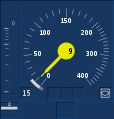
- Representation of the approach to a signal with 15 km / h release speed in the DMI

190 m before the end of the target speed monitoring (TSM) and the nominal curve at 48 km / h, the release speed is (h 15 km /) still do not use them ...

... also 50 m before the end of the TSM (target curve at 30 km / h).

20 m before the end of the TSM, the speed monitored by the target braking curve (8 km / h) has fallen below the release speed. Due to the release speed of 15 km / h, the approach is tolerated at 12 km / h.
After the TSM has expired, on the last meter before the signal, the signal is slowly approached using release speed (at 9 km / h, at a permissible 15 km / h).


Different release Speeds for ETCS danger point ( Danger Point ) and Durchrutschweg ( overlap ) are defined. In Germany, release speeds in operation with ETCS Level 2 on freight trains are measured with 66 brake hundredths . For example, with a slip distance of 55 meters, it is 15 km / h. An adaptation for areas in which only certain (passenger) trains run is being considered. In Austria, the release speed, regardless of the slip path, is 20 km / h in directional operation. When operated with ETCS Level 1 Limited Supervision , a release speed of 25 km / h is permitted in Germany.
If a release speed cannot be permitted, the target signal will be inaccessible due to safety margins of the ETCS odometry. This leads u. a. to reduced performance and reduced usable track lengths. For example, no release speed can be configured on signals without a slip path. Another example are ETCS exits at main signals with distant signal function, on which a 1000 Hz influence from the train etc. U. is not reliably recorded, because the level change is only commanded when the exit signal is in motion, but the train may move using the release speed at this moment. U. is already slightly behind the exit signal or PZB magnet.
Rigid relationships between permissible speed and slip path - e.g. B. 40 km / h at 50 meters in Germany - take a back seat in operation with ETCS Level 2. The permissible speeds resulting from the track plan (e.g. switches) are stored (configured) in the ETCS control center (RBC). On the basis of the element or route information transmitted by the interlocking, the RBC generates an ETCS travel permit in which u. a. the speeds permitted by the infrastructure as well as the slip path (overlap) are included. The permissible speed is no longer displayed in accordance with rigid rules on fixed light signals, but is calculated by the ETCS on-board unit using ETCS braking curves. The On-Board Unit ensures that a train can be brought to a stop in front of the danger point. Fixed light signals are, if any, in Germany, usually blanked to avoid contradictions to the flight deck display of ETCS. This makes it possible, especially with well-braking trains, to enter quickly even with comparatively short slip paths.
In Germany, a maximum of 70 meters long slip paths are used in operation with ETCS Level 2. With ETCS Level 2 “without signals”, which is possible in Germany to reduce the distances between danger points, increases in performance can be achieved. In addition, leeway is created in the layout of the track plan, for example by placing signals closer to switches.
By terminating the braking curve monitoring when the driving permission recording speed is reached, inaccuracies in the odometry of the vehicle are also compensated for. In full monitoring (FS) - regardless of the release speed - an emergency brake is triggered when the minimum safe front end has reached the end of the travel permit. Since this usually follows the actual position of the Zugspitze, an emergency brake is only triggered after the signal. The odometry error permitted with ETCS is 5 meters plus ± 5 percent of the distance covered since the last chained data point (one or more Eurobalises), or better. In addition, the laying tolerance of the underlying data point has to be added.
Instead of the time-dependent resolution, ETCS can also be used to resolve the slip path with the consent of the RBC when the train has come to a standstill.
LZB on German railways according to EBO
On German routes with regular train control (LZB) without CIR-ELKE system software, the slip path must not be shorter than 200 m, as this LZB version would otherwise not guarantee compliance with the LZB brake board. With the CIR-ELKE system software, the slip path is a uniform 50 m, regardless of the entry speed. This regulation was used for the first time on the CIR-ELKE pilot route Offenburg – Basel . The shortening is made possible by the continuous speed monitoring. With the introduction of CIR-ELKE, the locations of exit signals were checked and optimized.
On the main line of the Munich S-Bahn equipped with it, a distance of 55 m must be maintained between the LZB target stopping point and the danger point (end of the slip path or danger point distance) with S-Bahn-specific braking curves; the slip path or danger point distance itself is 50 m, as with block signals.
At the end of 1970, the slippage paths planned for LZB operation were 25 m.
Subways
In subway operations , a (short) block section is usually chosen as the slip path.
Web links
- ETCS in Zusi: We run level 1 full supervision . Video excerpt with explanation of the release speed functionality of ETCS
Individual evidence
- ↑ a b c d Ulrich Maschek: Securing rail traffic . Springer Vieweg, Wiesbaden 2012, ISBN 978-3-8348-1020-5 , p. 116, 118, 243-245 , doi : 10.1007 / 978-3-8348-2070-9 .
- ↑ a b Ulrich Maschek: Driving past signals indicating stop . In: Your train . No. 2 , 2016, ISSN 0948-7263 , p. 28-33 .
- ↑ Eisenbahn-Bundesamt (Ed.): Report of the Eisenbahn-Bundesamt according to Article 18 of the Directive on Railway Safety in the Community (Directive 2004/49 / EC, "Safety Directive") on the activities as a safety authority: reporting year 2014 . September 15, 2015, p. 9 ( bund.de [PDF]). PDF ( Memento of the original from February 27, 2016 in the Internet Archive ) Info: The archive link was inserted automatically and has not yet been checked. Please check the original and archive link according to the instructions and then remove this notice.
- ↑ Klaus-Rüdiger Hase, Sebastian Müther, Peter Spiess: New findings on the anti-skid behavior of electric multiple units . In: Railway technical review . tape 55 , no. 10 , 2005, pp. 599-610 .
- ↑ Jörn Pachl : Special features of foreign railway operating procedures: Basic terms - interlocking functions - signaling systems . 1st edition. Springer Fachmedien Wiesbaden, Wiesbaden 2016, ISBN 978-3-658-13481-5 , p. 34-36 .
- ^ Colin Bailey: European Railway Signaling . Ed .: Institution of Railway Signal Engineers. A & C Black, London 1995, ISBN 0-7136-4167-3 , pp. 109 f .
- ^ Haldor Jochim, Frank Lademann: Planning of railway systems. Basics - planning - calculation , Hanser Verlag, 2008, ISBN 978-3-446-41345-0 .
- ↑ a b Deutsche Bahn AG: Guideline 819 “Planning LST Systems”, Module 819.0202 of December 10, 2006, Section 11, Paragraph 4.
- ↑ Deutsche Bahn AG: Guideline 819 “Planning LST Systems”, Module 819.0202 of December 10, 2006, Section 11, Paragraphs 6 to 9.
- ^ Rudolf Lütgert: The inductive train control at the German Federal Railroad . In: signal + wire . tape 52 , no. 8 , August 1960, ISSN 0037-4997 , p. 133-144 .
- ↑ Preliminary principles for the side protection of the routes on main lines . In: Journal for the entire railway security and telecommunications system . tape 25 , 1930, ISSN 0037-4997 , pp. 54-56 .
- ↑ Restrictions for the danger point distances for main signals . In: Journal for the entire railway security and telecommunications system . tape 48 , 1956, ISSN 0037-4997 , pp. 33 .
- ↑ Deutsche Bahn (Ed.): Guideline 819.20 - Design of the safety systems of the S-Bahn Berlin and Hamburg .
- ^ Deutsche Bahn (ed.): Local guidelines for the S-Bahn Hamburg
- ^ Deutsche Bahn (Ed.): Special provisions for the operation of the Berlin S-Bahn
- ^ Ludwig Wehner: Signal system of the S-Bahn Munich . In: signal + wire . tape 62 , no. December 12 , 1970, ISSN 0037-4997 , pp. 209-222 .
- ^ "Jörn Pachl: System technology of rail traffic, information for readers from Austria." Retrieved January 11, 2012 .
- ^ Peter Schmid: 39th conference "Modern Rail Vehicles" in Graz . In: Eisenbahn-Revue International . No. 6 , 2010, ISSN 1421-2811 , p. 294-296 .
- ↑ Collision in Süssenbrunn . In: Rail transport currently . No. 5 , May 2017, p. 216 .
- ↑ Maximilian Wirth, Andreas Schöbel: Minimum headway times for ETCS Level 2 and Level 3 on the Vienna S-Bahn main line . In: signal + wire . tape 112 , no. 4 , 2020, ISSN 0037-4997 , p. 21-26 .
- ↑ Implementing provisions for the Railway Ordinance (AB-EBV) DETEC , July 1, 2016 (PDF; 3 MB). AB 39.3.a, point 4 flank protection and slip path
- ↑ Ivo Myslivec, Bozetech Šula: Automatic train control and ETCS in the Czech Railways . In: signal + wire . tape 91 , no. 10 . Tetzlaff Verlag GmbH & Co. KG, 1999, ISSN 0037-4997 , p. 20-23 .
- ↑ a b ERA / UNISIG / EEIG ERTMS Users Group: ERTMS / ETCS - Baseline 3, System Requirements Specification, Chapter 3, Principles (Version 3.4.0). January 6, 2015 (current version online ), page 47 f., 55, 126, 183.
- ↑ Olaf Gröpler: Braking distances and braking distance safety at ETCS . In: ZEVrail . tape 132 , no. 1-2 , January 2008, ISSN 1618-8330 , p. 31–39 (According to the text, the essay is a revised version of a lecture given in November 2006. It thus obviously represents the status from the end of 2006.).
- ↑ Sven Haaker: Planning LST systems . ETCS-L2 high-performance block. Ed .: Deutsche Bahn. January 7, 2020, p. 4, 8 (guideline module 819.0519).
- ↑ a b Study on the introduction of ETCS in the core network of the Stuttgart S-Bahn. (PDF) Final report. WSP Infrastructure Engineering, NEXTRAIL, quattron management consulting, VIA Consulting & Development GmbH, Railistics, January 30, 2019, pp. 87 f., 283, 420 , accessed on April 13, 2019 .
- ↑ Ulla Metzger, Henri Klos: The Train Control Simulator (TCSim) from DB Systemtechnik . In: The Railway Engineer . tape 61 , no. 8 , 2010, ISSN 0013-2810 , p. 44-48 .
- ↑ According to subset 26, 3.13.10.2.6, the “minimum safe front end” from vehicle odometry is used
- ↑ ETCS specification, subset 026, version 3.6.0, section 3.8.1.1 e)
- ↑ Gamma trains under ETCS L1LS. (PDF) Braking performance. In: fahrweg.dbnetze.com. DB Netz AG, June 20, 2019, pp. 10, 12 , accessed on July 29, 2019 .
- ^ A b Hannes Goers, Peter Reinhart, Rüdiger Weiss: Stuttgart node. (PDF) ETCS as a carrier for performance and quality improvements. In: vm.baden-wuerttemberg.de. DB Netz , DB Projekt Stuttgart – Ulm , January 9, 2019, p. 16 , accessed on April 24, 2020 (German).
- ↑ Peter Reinhart: ETCS & Co for "maximum performance". (PDF) A workshop report on the Stuttgart digital node. DB Projekt Stuttgart – Ulm GmbH , November 21, 2019, p. 26 , accessed on November 22, 2019 .
- ↑ ETCS specification, subset 041.
- ^ Walter Fuß, Dagmar Wander, Patrick Sonderegger, Leif Leopold ,: Railway safety technology in Swiss tunnels . In: signal + wire . tape 111 , no. December 12 , 2019, ISSN 0037-4997 , p. 44-50 .
- ^ Alwin Murra: Introduction of the CIR-ELKE-HBL on the pilot route Offenburg - Basel . In: Signal + Draht , Volume 91, Issue 7 + 8, pp. 13-16, July / August 1999.
- ^ Karl-Heinz Suwe: CIR-ELKE - a project by Deutsche Bahn from the perspective of railway signaling technology . In: Swiss Railway Review . No. 1, 2 , 1993, ISSN 1022-7113 , pp. 40-46 .
- ↑ Ulrich Oser: Overall operational concept for CIR-ELKE . In: Deutsche Bahn . tape 68 , no. 7 , 1992, ISSN 0007-5876 , pp. 723-729 .
- ^ Fritz Eilers, Wolfgang Ernst: The installation of the high-performance block (HBL) with linear train control . In: Deutsche Bahn . tape 68 , no. 7 , 1992, ISSN 0007-5876 , pp. 768-770 .
- ^ Klaus Hornemann: Line train control on the Munich S-Bahn . In: Eisenbahn-Revue International . Issue 6/2006, ISSN 1421-2811 , pp. 306-311.
- ^ Eduard Murr: Line train control - current state of development . In: signal + wire . tape 71 , no. November 11 , 1979, ISSN 0037-4997 , pp. 225-232 .