
Niederfinow boat lift
| Niederfinow boat lift | ||
|---|---|---|
 Niederfinow ship lift, 2017, in the background the new lift |
||
| Data | ||
| place | Niederfinow ( Brandenburg ) | |
| Construction year | 1934 | |
| height | 60 m | |
| Floor space | 2538 m² | |
| Coordinates | 52 ° 50 ′ 56 " N , 13 ° 56 ′ 29" E | |
|
||
| particularities | ||
| - Industrial monument according to the Hague Convention for the Protection of Cultural Property in the Event of Armed Conflict - Historical landmark of civil engineering in Germany |
||

The Niederfinow boat lift , which went into operation on March 21, 1934, is the oldest still working boat lift in Germany . It is located at the eastern end of the Oder-Havel Canal in Niederfinow / Brandenburg and overcomes the height difference of 36 meters between the apex position and the Oder position of the federal waterway Havel-Oder waterway , for which the Eberswalde Waterways and Shipping Office is responsible.
The building is a protected industrial monument under the Hague Convention for the Protection of Cultural Property in the Event of Armed Conflict . In December 2007 it received the award for the first time awarded by the Federal Chamber of Engineers as a Historic Landmark of Civil Engineering in Germany .
The Niederfinow Nord boat lift, which is suitable for larger ships, will be built parallel to the previous lift . The new elevator is to replace the old one by 2025 at the latest.
history
History of origin (1906–1927)


.jpg)
Since the second Finow Canal , built between 1743 and 1746, had reached its limit at the end of the 19th century, the Prussian government passed a law of April 1, 1905, resolving the construction of the Berlin-Stettin major shipping route, which began in September 1906 with the first groundbreaking started. This law also laid the foundation stone for the Niederfinow ship lift. In the public competition announced by the Prussian Ministry in 1906 for the descent structure in Niederfinow, ten designs were received, six for the construction of vertical lifts. In October 1908, however, it was decided to build a lock staircase . At the same time, further investigations for a second descent structure should be made with the following basic ideas:
- simple vertical lifting with counterbalance,
- swinging lifting by balance beam,
- semicircular lifting by a floating drum.
In 1912 the second, limited competition ended. The winner was the design by Beuchelt & Co. in Grünberg (Silesia) : ship lift with equal-arm balance beam. This draft was a further development of a contribution to the tender from 1906. The government approved the draft of a ship lift with balance beam drawn up by the royal construction management in Eberswalde in 1914 and ordered it to be carried out. In 1918 the elevator was supposed to go into operation, but the First World War thwarted all these plans.
After the First World War , planning for the elevator was resumed. The drafts from 1906, 1912 and 1914 were examined and further developments were incorporated. The result was available in September 1923. Due to new findings on operational safety, which in the case of lifts with lifting cylinders, rocking levers and balance beams were based on very few moving, heavily loaded components, the plans were discarded and the system of lifting with counterweights hanging on wire ropes was considered. By dividing the trough weight over a large number of wire ropes, sheaves, bearings and counterweights, a certain operational reliability could be achieved even if several parts failed. Another reason for the system change were changed framework conditions. Whereas the earlier plans were designed for ships with a capacity of 650 tons, ships with a capacity of 1000 tons should now be funneled. Here one saw the fewest difficulties in the counterweight lift.
A momentous change in the political arena took place as early as 1921, when the Reich Waterways Administration took over responsibility for project development from the former Royal Building Administration Eberswalde, henceforth the Eberswalde Construction Office. The new building office under the direction of Kurt Plarre worked through all the proposals again and presented the ministry with a draft of a counterweight lift with a spindle safety device. At the same time, the Reich Ministry of Transport developed its own project.
In 1923, the ministry commissioned the Eberswalde new building office to test the lifting mechanism with a turning bolt, which had been developed by senior government building officer Alfred Loebell since 1921. The Loebell system provides a safety system coupled with the drive. Four screw spindles (turning bolts) rotate in a double-slotted nut (nut jaw column) synchronously with the trough travel. After the presentation of the Loebell system, there were various, sometimes difficult, debates between the engineers of the Reich Ministry of Transport and the engineers of the Eberswalde new building office about the manufacturability and usability of the individual trough drive variants.
With a decree in March 1924, the Reich Ministry of Transport ended all discussions and rejected all other alternatives to the Loebell system, which it favored. At the same time the revision of all drawings and plans and the creation of an overall design were ordered. This overall draft should be the basis for the production of models and at the same time serve for submission to the Academy of Building for assessment. After incorporating any objections from the Academy, the overall design served as the basis for the tender.
Extensive investigations into the geological conditions in Niederfinow and the requirements of the ropes followed. Various components were tested on large models in the Eberswalde Ardelt works .
On May 11, 1927, the Academy of Civil Engineering published its approval report and the way for the construction of the Niederfinow ship lift was clear. On the basis of the carefully worked through design, a highly solid, reliable work of technology was created.
Construction (1927–1934)
Construction site equipment

In order to be able to cope with the construction of the ship lift, a large construction site facility was required. This was carried out in parallel to the extensive subsoil investigations from 1925 onwards. Temporary transshipment points were created in the upper and lower harbor of the lock staircase. The delivered materials were transported to the construction site using a specially set up construction site tram. Railway cars with components were brought to the construction site via a ferry connection between Atomill (a district of Niederfinow) and a temporary pier above the Lieper lock on the Finow Canal. Only the remains of the foundations can be seen today from the port with siding that already existed in Atomill.
In a mixing plant, the gravel, which came from the Niederfinow gravel pits near the construction site and was brought in by cable car, was mixed with the delivered cement , grit and trass . Workshops for wood and metal work, storage rooms, several residential buildings, a canteen and a large office building were built. The entire construction site facility had its own sewer system. To secure the power supply during the construction phase, a diesel engine power plant was built. At the same time, the Niederfinow – Liepe road was diverted as an emergency road in a large arc around the construction site.
After the completion of the ship lift, the office building was converted into a restaurant. The power plant was kept operational until 1990. Because of the new elevator construction, both buildings had to be demolished, the power house was rebuilt elsewhere as a display system.
Foundation
In order to get an overview of the subsoil, a soil profile was created with the help of around 300 boreholes. The result of the subsoil investigation was that the lift moved away from the slope, which resulted in a longer canal bridge. The foundations of the pillars of the canal bridge should have the same foundation depth as the base plate of the ship lift. Likewise, with an expert opinion of October 11, 1926, the order for the construction of the basic structures from east to west was determined. In addition, the groundwater should be lowered.
In late autumn 1926, the excavation of the construction pit for the foundation of the elevator began. A groundwater lowering system was put into operation. In 1927 and 1928 the lower outer port was completed as far as the emergency road, the upper port with its extensive bottom seal, the piers, embankment walls, the security gate and the land abutment of the canal bridge.
The actual foundation of the ship lift started in the summer of 1928. The construction pit was excavated approx. 10 meters deep and a large part of the slope was removed for the foundation of the east pillar of the canal bridge. It was not possible to lower the groundwater any deeper, considering lock IV of the lock staircase. The foundation pillars of the trough chamber floor had to be built into the groundwater at a depth of around 20 meters below the surface, up to the load-bearing ground. This was done using the compressed air foundation method. Steel scaffolding with an area of up to 300 m² was riveted together and covered with concrete. This resulted in caissons with sharp edges all around, which inside had a working space of about 2.20 meters high.
The soil, which was loosened under the cutting edges, was carried up through an opening in the ceiling, and the box continuously sagged due to its heavy weight. When the groundwater level was reached, everything was sealed airtight and compressed air was pressed into the work area through a pipe. This drove the water out of the work room. As long as the working chamber was under air pressure, the caisson no longer sagged by itself. This was only achieved again after the overpressure was reduced. When the foundation depth was reached around 10 m below the groundwater level, there was an overpressure of around one bar in the working area .
The east pillar of the canal bridge, which was lowered in 1929 and has a total height of 29 meters, reaches 19 meters below the groundwater. At the final depth there was an overpressure of around two bar in the working chamber. The west pillar of the canal bridge with its total height of 22 meters could be lowered without compressed air, since water was only encountered in the foundation base. As soon as the piers had reached the desired depth, the working chambers and the elevator shafts were filled with concrete.
The foundations of the ship lift and the east pillar were completed in 1929, the entire trough chamber and the west pillar in 1930.

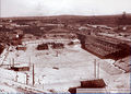
November 5, 1927: Elevator pit from the west
1928: Excavation from the northwest
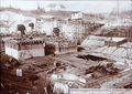
October 30, 1928: Caisson group II during lowering
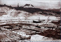
April 18, 1929: Production of the sole seal for parts I and II of the trough chamber sole and application of the protective concrete layer

May 23, 1929: reinforcement of the trough plate; Looking north

October 4, 1930: Tail unit and anchor sheet piling in the lower harbor before backfilling


Erection of the elevator
A 60 meter high gantry crane was erected in the autumn of 1930 to erect the hoist scaffolding . It had a track width of 46.70 meters and a total working width of around 56 meters. It spanned the entire trough chamber. The operating weight of the crane was 237 t. With this crane it was possible to lift prefabricated steel components of up to 25 t. The entire operation of the crane was carried out from the control stand of the machine house, which was located at a height of 30 meters on the crossbar of the two northern portal supports.
In February 1931, the actual erection work of the hoist scaffold began in the following order: central tower, west tower, east tower. While the west tower was being erected from the summer of 1931, the mother-jaw columns were installed in the central tower at the same time. Then the installation of the trough began. After the east tower was also erected in autumn 1931, an auxiliary frame made of wood was erected for the construction of the canal bridge. In the spring of 1932, the entire hoist frame including the essential fixtures was erected. In autumn 1932 the canal bridge was also completed.
In April 1933, the trough with all its technical equipment was so far ready that the first test runs could be carried out with an empty trough and correspondingly fewer counterweights. In October 1933 all the counterweights were attached, the trough was completely filled with water and the steel structure was finished. The lifting height of the trough is 36 m. At the beginning of March 1934 there was a twelve-day acceptance operation and on March 21, 1934 the ship's lift was handed over to its destination.
Participating companies

The following companies were involved in the construction, which cost 27.5 million Reichsmarks :
|
management
|
Machine systems
Electrical systems
Basic and steel construction of the canal bridge
|
Company (since 1934)

.jpg)
Ships without their own propulsion were pulled by towing locomotives at the Niederfinow lock staircase from 1914 . This procedure was also practiced at the ship lift. There was an extensive track network on which up to 20 tow locomotives operated. After the abandonment of the uneconomical tugboat business, the tow locomotive system was shut down in the 1960s. One of the machines is a restored monument on the canal bridge to the west of the elevator.
Already on January 26, 1939, the barge of the ship Haak became the 100,000th ship to be locked. The freight traffic in the founding year amounted to 2,832,000 tons.
In 1980 the hoist underwent a general overhaul, in 1984/1985 the suspension ropes were also renewed.
Today the ship's lift is too short for push convoys, so the units have to be separated. Today it has reached its capacity limit with around 11,000 ships annually, which is why it was decided in 1997 to build a new larger elevator.
The Niederfinow boat lift is a popular destination for around 150,000 visitors every year. That is why a new, larger car park was opened in 2003.
Elevator ladder
| Period | ladder |
|---|---|
| March 1934 to November 1945 | Karl Schlegel |
| November 1945 to December 1945 | Fritz Stahl |
| January 1946 to 1962 | Hugo Freudenberger |
| 1962 to 1976 | Günther Kaiser |
| October 1976 to 1990 | Hans-Jürgen Völter |
| 1990 to December 1998 | Willi Dükomy |
| January 1998 to April 2001 | Udo Poppe |
| Since May 2001 | Jörg Schumacher |
- Source: 75 years of Niederfinow ship lift
Accidents
In addition to the planned closing times, mostly in winter between December and March, which are used for repair purposes, there have also been failures due to technical malfunctions and natural events since 1934. Shortly before the end of the Second World War, the expansion for the operation of important electrical components resulted in a war-related shutdown, which lasted until August 1945. After a dike breach on the Oder in the spring of 1947, the entire northern Oderbruch was flooded. The maximum water level was reached on April 5, 1947 at 5.85 meters above sea level. At the ship lift, the water rose 3.70 meters above the normal water level and put the operating rooms of the lower section under water almost two meters. Only at the end of May 1947 could operations be resumed. By the end of 2007, the ship lift had lost 47 days due to technical defects.
| Failure reason | Period | Lost days |
|---|---|---|
| A wedge on the ring shaft of the north-west drive engine had come loose. | 1st - 12th April 1944 | 12 |
| A tensioning screw on the southwest swivel lock had loosened, causing the swivel lock to get misaligned and stuck. | 3rd - 10th June 1951 | 8th |
| Broken ball bearing on a drive screw of the lower bracket sealing frame. | June 29th – 5th July 1963 | 6th |
|
Interturn shortcut on the converter drive motor: the motor was removed and rewound. On November 30, 1963, the original engine was reinstalled. In the meantime, an auxiliary engine handled shipping operations. |
16.-30. November 1963 | 6th |
| A stud bolt broke on the gate drive of the lower section. | 22-25 September 1979 | 4th |
| The hydraulic drive of the sealing frame in the upper section could no longer be moved. | 17.-18. December 1988 | 2 |
| A double T-beam about eight meters long and 34 cm high that had been towed into the trough by a ship had to be recovered by divers. | 29-30 September 1997 | 2 |
| The drive shaft of the Quarter-Turn Northwest was deformed when the Quarter-Turn was put on. The spring pot switch had not switched off the drive. |
22.-24. July 1998 | 2 |
| The bushing of the lower runner block at the north-west quarter-turn bolt seized on the throat of the quarter-turn bolt. The trough came to a stop in front of the upper post. |
17th to 20th April 2000 | 3 |
| Due to an electrical defect on the speed controller, the trough could only be moved in the "fine travel" operating state. | 15.-16. November 2007 | 2 |
- Source: 75 years of Niederfinow ship lift
technology
The lift is 60 meters high, 94 meters long and 27 meters wide. The trough takes five minutes to overcome the height difference of 36 meters. The total duration of a lock is 20 minutes. The ship lift consists of a 14,000- ton steel structure held together with five million rivets , which stands on steel pillars. The structure was founded with steel-reinforced concrete that was placed up to 22 meters deep. The base plate is four meters thick. The Oder-Havel Canal is brought up to the head of the elevator with a riveted trough bridge with a mass of 4000 tons. The trough, which is filled with water, weighs 4,290 tons, is 85 meters long, 12 meters wide and has a water depth of 2.50 meters. It hangs here on 256 steel cables (diameter 52 mm), which are guided over pulleys (diameter 3.50 meters, weight five tons each) with 192 counterweights made of concrete, also weighing 4,290 tons, to balance the trough. In order to eliminate the moving rope load of the steel ropes, four rope weight compensation chains are used. The safety of the guidance on the ropes is achieved by a tensioning device in which half of the ropes actually carry the trough and the other half is carried as a reserve without tension.
The symmetrical drive via a rack and pinion gearing is realized with DC motors , which in turn with an annular shaft are connected to each other. This arrangement enables the four pinion pinions to rotate synchronously . The motors have an output of 55 kilowatts each and are supplied by a Leonard converter (alternating to direct current). Furthermore, four threaded shafts ("twist locks") mounted vertically on the trough are driven, each of which engages in a slotted internal thread ("nut jaw column") along the path of the trough. This is a safeguard against falling or being torn up the trough in the event of a rope break or the trough leaking. The thread usually has play. Only in the event of an accident do the twist locks support themselves in the nut thread: towards the bottom or towards the top.

Information board on the A 11 motorway
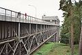
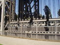
Steel structure of the access bridge
Counterweights of the trough

The bottom of the elevator is always water-free

Model: Quarter-turn in the nut jaw column (partially cut on the left)


The boat lift works with practically no water loss. This is an advantage over the locks in terms of ensuring water retention. The stair locks were operated as economy locks , which partially compensated for the water loss.
New boat lift

The existing elevator is at the limit of its capacity and no longer meets today's requirements. It is a bottleneck because its trough length limits the length of the ships to 84 m. This means that modern vehicles up to 110 m in length cannot pass. In addition, they cannot use their loading capacity as the trough water depth only allows a 2.00 m draft. Its capacity is not sufficient for an expected passage of around 4.4 million tons of goods per year in the direction of Berlin. In addition, after around seventy years of operation, repair work becomes necessary, for which shipping traffic has to be blocked for a long time. For these reasons, the construction of a new descent in Niederfinow was included in the federal transport route planning in 1992.
In 1997 it was decided to build the new, larger Niederfinow Nord ship lift . In the autumn of 2006, the earthworks began between the current lift and the lock staircase and the fourth (lowest) lock was partially demolished. The foundation stone was laid on March 23, 2009 by the then Federal Transport Minister Wolfgang Tiefensee and Brandenburg's Prime Minister Matthias Platzeck . The trough is to have a usable length of 115 meters, a usable width of 12.5 meters and a depth of four meters (suitable for large motor cargo ships ) and weigh 9,800 tons when filled. Since a ship always displaces as much water as it weighs itself, the weight of the water-filled trough always remains the same. The costs in 2008 should amount to 285 million euros. The first passage should take place in 2017, but the old elevator should remain in operation until at least 2025. Completion "possibly 2019" was planned for mid-2018, the costs were 300 million euros. January 2020 was named as the date 2021.
Others
The Niederfinow ship lift was used as a backdrop in films - for example for the showdown in Wim Wenders ' In Far Ferne, so nah! . In police call 110: Jürgen Heinrich's last trip is in a motor ship through the ship's lift.
Since in the inland waterway traffic regulations the ascent on the Havel-Oder waterway is defined as a journey in the direction of the Oder, the Niederfinow ship lift has the linguistic peculiarity that one drives “up the mountain” while the trough moves downwards.
See also
literature
- o. V .: The ship lift for the descent of the large shipping route Berlin-Stettin to the Oder near Niederfinow. In: Deutsche Bauzeitung , Volume 47, 1913, No. 22 (from March 15, 1913), p. 199 f. (Presentation of the design by Beuchelt & Co. intended for implementation in 1912 and overview of the planning process so far)
- Ellerbeck: Design work for the ship lift near Niederfinow. In: Die Bautechnik , 5th year 1927, issue 23 (from May 27, 1927), pp. 319–338.
- W. Riezler: The Niederfinow ship lift. An engineering aesthetic problem . In: Die Form, Vol. 3, pp. 33 – p. 36 ( digitized version ).
- Ellerbeck: The Niederfinow ship lift. In: Newspaper of the Association of Central European Railway Administrations, Volume 74, 1934, No. 16 (from April 19, 1934), pp. 293–297.
- H.-J. Uhlemann: Berlin and the Märkische waterways . DSV-Verlag, Hamburg 1994, pp. 69-74.
Web links
- Entry in the monument database of the State of Brandenburg
- Eberswalde Waterways and Shipping Office: Niederfinow ship lift , new ship lift
- New waterway construction office in Berlin: Niederfinow ship lift
- Historical photos of the elevator construction on oder-havel-kanal.de
Individual evidence
- ^ The Niederfinow ship lift ( Memento from December 5, 2014 in the Internet Archive )
- ↑ 75 years Niederfinow ship lift, WSA Eberswalde 2009 pages 12–18 and 26
- ↑ Technology I Niederfinow ship lift 1991 Peter Zablowski
- ^ Eckhard Schinkel: The old Niederfinow ship lift . Federal Chamber of Engineers 2007
- ↑ Technology I, Niederfinow ship lift 1991, Peter Zablowski
- ↑ In relation to 1934, adjusted for inflation, this corresponds to 123,100,000 euros in today's currency. This figure was based on the template: Inflation determined, has been rounded to a full 100,000 euros and relates to last January.
- ↑ Repair of the historic towing locomotive at the Niederfinow ship lift at the Eberswalde Waterways and Shipping Office, accessed on October 30, 2018.
- ↑ The original. In: Berliner Zeitung . October 16, 2006.
- ↑ WSA Eberswalde 2009, pages 80–81
- ↑ 75 years Niederfinow ship lift, WSA Eberswalde 2009 page 82
- ^ Wasserstraßen Neubauamt Berlin, History of the Niederfinow Hebewerkes Hebewerkes Niederfinow, wna-berlin.de
- ↑ Foundation stone laid for ship lift (tagesschau.de archive) on tagesschau.de
- ^ Journal of Inland Shipping, issue 4/2009, p. 12f
- ↑ Large inland waterways should be able to travel from Berlin to Stettin . In: Die Welt , March 29, 2008
- ↑ The new ship lift is due to open in 2019. 2018, accessed August 5, 2019 .
- ↑ Trial operation for the Eberswalde ship lift delayed