
Fiber optic connector


Fiber optic connectors are special connectors for the detachable connection of fiber optic cables (FO) or fiber optic cables. Optical fibers can be connected to one another or to other components via these. In the communications technology are the transmitter, receiver or amplifier, in the measurement technology , spectroscopy or medical technology , for example, laser devices, light - sensors or radiation detectors .
The majority of the plug connections used today are plug-plug connections. The connectors used must have the lowest possible signal attenuation (also insertion loss ) and high return loss , as well as high reproducibility and maintenance of these parameters over several hundred connection cycles.
The most frequently used connector types in communications engineering are LC and SC, although ST and E-2000 are also widely used from older installations. FC and F-SMA connectors are mainly used in laser and measurement technology. In the digital transmission of audio signals , such as from CD , DVD players and flat screen televisions to audio amplifiers , are mainly TOSLINK plug used.
history

Early designs
Previously, so-called been lens connector (engl. Expanded beam connector ) is used in which the light by a lens at the fiber output is collimated , and the plug of the receiving fiber having a same lens back onto the fiber end face focus is. The advantage of this plug connection is the relative insensitivity to axial misalignment or contamination, which is why some of them are still used today for use in harsh environments. The serious disadvantage of this technology is the very large size and the relatively high signal attenuation due to the reflection losses at the many air-glass interfaces (insertion loss in the range of 1–2 dB ). In order to reduce the insertion loss, the contact connectors that are mainly used today were introduced, in which the fiber end faces come as close as possible or touch one another directly. This also makes it possible to implement particularly small designs with up to a hundred fibers in one connector.
End face shape

Through the use of spring-loaded, very precise cylindrical sleeves for receiving fibers (so-called ferrules ), which are brought into direct contact in the connector receptacles, the insertion loss could be reduced to values of 0.1-0.5 dB. The ferrules, which are mainly made of metal or ceramics , are specially ground or polished with the glued-in fiber . In the past, the end faces were made flat at right angles to the fiber axis, but this had certain disadvantages:
- The contact pressure was distributed over the entire connector end face and not just over the area of the fiber core relevant for the transmission.
- Manufacturing tolerances, contamination or damage to the connector end face (also outside the core area) can lead to an air gap between the two connectors when connecting, which results in increased attenuation and reflectivity of the connection.
| abbreviation | designation | Reflectance | Return loss |
|---|---|---|---|
| Pc | Physical contact | <−30 dB | > 30 dB |
| SPC | Great physical contact | <−40 dB | > 40 dB |
| UPC | Ultra physical contact | <−50 dB | > 50 dB |
| APC | Angled Physical Contact | <−60 dB | > 60 dB |
In order to avoid the problems mentioned, so-called PC plugs were developed ( physical contact ) with a rounded end surface (radius approx. 10-15 mm), which only make physical contact with the fiber cores when plugged in. Almost all high-quality connectors today are at least PC connectors and often have a “PC” as a supplement to their designation (such as ST / PC, SC / PC, FC / PC, etc.).
Ever higher demands on the return loss ( reciprocal value of the degree of reflection ) of the installed plug connections ultimately led to ever better polishing qualities of the PC connector, including the grades SPC ( super physical contact ) and UPC ( ultra physical contact ) belong. A further increase could then only be achieved with the so-called HRL connectors ( high return loss ) or APC connectors ( angled physical contact ) (see table for values for the return loss ). With this type of connector, the connector end face is not only convex, but the normal to the fiber end face is also tilted by a few degrees (standard is 8 °) to the fiber axis. Due to this structure, light reflected from the connector end face is refracted from the core via the cladding glass into the air and can therefore no longer disrupt the data transmission (see Fig.). Connectors of this type have an APC as a supplement to their designation (ST / APC, SC / APC, FC / APC, LC / APC, LSH / APC etc.). UPC and APC connector types are used especially for single-mode fibers .
Connector types
The most frequently used connector types today are LC ( lucent connector ) and SC ( subscriber connector ). From older installations, ST ( straight tip ) and E-2000 are also widely used. Like the MU connector, the LC connector is one of the so-called small form factor connectors (SFF connector). These have 1.25 mm ferrules and, thanks to their smaller design, enable a higher assembly density than older connectors, such as the SC, ST and E-2000 connectors with 2.5 mm ferrules. A further increase in port density can be achieved with multi-fiber connectors with MT ferrules ( mechanical transfer ), such as the MTRJ, MPO or MTP connector. MT ferrules typically contain 2 (MTRJ) to 16 (MPO / MTP) fibers per row (fiber spacing 250–750 µm) and the alignment of the multi-fiber ferrule is carried out by two laterally attached high-precision guide pins that are either in the connector itself or are in the plug receptacle.
F-SMA (SMA 905/906)
.jpg)
The F-SMA connector is the oldest fiber optic connector and was developed by Amphenol in the late 1970s on the basis of the SMA connector for HF applications. To distinguish it, the designation is usually preceded by an F (F-SMA for fiber sub-miniature assembly ). The fiber holder with a 3.175 mm ferrule made of stainless steel (rarely also made of ceramic ) was incorporated into the existing design, characterized by the hexagonal nut . The connector is not twist-proof and the fibers of two connectors cannot be brought into physical contact. A so-called end face contact is therefore established between the ferrules without the fiber end faces touching one another. The connector is only used for multimode fibers and is only found in older installations in the telecommunications sector (too large design and relatively high insertion loss). Due to its robust construction, however, it is still used in measurement technology, medicine and the military, and is also offered in the IP65 protection class . In addition to the typical F-SMA connector (SMA 905) that is still used today, there is another design with a slightly different ferrule design (SMA 906), which has a step in the front ferrule area to accommodate a guide sleeve.
FC

The FC connector (FC for fiber connector ) was originally developed by NTT . As with the F-SMA connector, the locking is implemented using a screw cap (round knurled nut ). An axially spring-mounted 2.5 mm ferrule made of stainless steel or ceramic is incorporated in the metal connector housing (or ceramic ferrule with a metal insert, as in the core-core centering technique ). For the physical contact of the fibers in a plug-plug coupling, the end faces are convex and marked with FC / PC (0 ° bevel) or FC / APC (8 ° beveled bevel). The insertion loss is significantly lower than with the F-SMA connector and is around 0.2 dB. The connector housing has an anti-twist device in the form of a feather key , whereby two incompatible designs with different widths are available on the market, which also differ slightly from manufacturer to manufacturer: the R type ( reduced or narrow key ) with 1 , 97–2.02 mm and the N-type (for NTT-type or wide-key ) with 2.09–2.14 mm. The FC connector is mainly used for normal and polarization-maintaining single-mode fibers, but is also suitable for multimode fibers. Today it is no longer used in the telecommunications sector, but is still very popular due to the very good stability of the connection (as is the F-SMA connector for multimode fibers). It is used, for example, for fiber coupling of lasers, as well as in measurement and medical technology.
ST (BFOC)

The ST connector (ST for straight tip ) was developed by AT&T and is also known as the BFOC connector (for bayonet fiber optic connector ) due to its bayonet lock . In the past it was used a lot in local area networks ( LAN ) (replaced the F-SMA connector at that time). The connector housing is made of metal or plastic and the 2.5 mm ferrule is usually made of ceramic (metal versions are also possible). This connector is suitable for both monomode and multimode fibers, and is mainly used for multimode applications. The mean insertion loss is 0.3 dB, the maximum 0.4 dB. There are two designs of the ST connector that differ in the design of the bayonet lock. In some designs, the lock for receiving the locking pin is open in the axial direction, and in others it is closed, but has a groove for inserting the pin. Furthermore, it has an anti-twist device, which is a bit of a hindrance when plugging in (as with the FC connector) and led to the development of connectors with rectangular housing shapes.
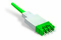
SC

Duplex SC connector multimode with visible ferrules

Duplex SC connector single mode with protective caps


The SC connector (SC for subscriber connector ) was developed by NTT in Japan and replaced the ST connector from the EN50173 and ISO 11801 standards as the standard for LAN cabling in 2002 (but is expected to be included in the new version of EN50173 and ISO 11801 to be replaced by the smaller LC connector). It is characterized by its plastic housing in a rectangular design (cross-sectional dimensions approx. 9 × 9 mm) and its push-pull technology (the connector locks automatically when plugged in and unlocks when pulled out). This allows faster and easier assembly, as well as a higher assembly density than all previous models (such as F-SMA, FC or ST). The SC connector has a 2.5 mm ferrule, mostly made of ceramic (metal versions are also possible), and can be used for multimode and single-mode fibers. The ferrule end faces are also available as an APC version and the mean insertion loss is around 0.2 dB. Another advantage over the ST connector is the ability to create duplex connectors (two connectors are connected via a duplex clip) and thus to insert or remove duplex connections at the same time. An anti-rotation device results automatically from the rectangular design.
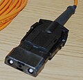
LSH / E-2000

E-2000 connector

(Protective flap open)


The standardized LSH connector was developed by the Swiss company Diamond and launched on the market under the trademark E-2000. An LSH connector has a 2.5 mm ceramic ferrule with a metal insert ( core-core centering technology ), which is also available in an APC end face design. The connector is unlocked using a lever, similar to the LC. It also has a special laser protection flap that opens automatically when it is plugged in. It minimizes the risk of contamination so that the separate protective caps that are common with other connector types can be dispensed with. The LSH connector has established itself across Germany for routes in city networks ( Metropolitan Area Network , MAN) and wide area networks ( Wide Area Network , WAN). It can be used for multimode and single mode fibers and the insertion loss is in the range of 0.1-0.2 dB. The E-2000 connector is also manufactured by R&M and Huber & Suhner under license from Diamond . Diamond is the only manufacturer to actively center the core during production.
ESCON
ESCON connector

MIC (FDDI) connector


ESCON ( Enterprise Systems Connection ) is one of IBM developed and 1990 introduced communications system for exchange of large amounts of data between mainframes (engl. Mainframe ) and the periphery thereof on the basis of optical waveguides (now superseded by FICON ). The fiber optic connector used is similar to the MIC connector, a duplex connector with two 2.5 mm ceramic ferrules, but in contrast to the rigid cover or protective cap of the MIC connector, it has a movable one that pulls the ferrules when the connection is made releases. The ESCON connector is intended for multimode fibers and, like other multiple connectors, its insertion loss is in the upper range, at 0.3–0.5 dB.
MIC (FDDI)
MIC connector ( medium interface connector ) is similar to ESCON connector, a duplex connector for accepting two fibers and is used almost exclusively in FDDI networks and sometimes on ATM components. Like the ESCON connector, it has two ceramic ferrules with a diameter of 2.5 mm in a plastic housing. It is intended for multimode fibers and has a typical insertion loss of 0.3–0.5 dB. Due to the housing design, it is non-interchangeable and also offers the option of attaching different codings for different data links .
MU (Mini-SC)
The MU connector ( miniature unit-coupling or multi-termination unibody ), also known as mini-SC connector , is a small form factor connector with push-pull technology developed by NTT . It is only about half the size of the SC connector and available as a simplex and duplex version. The MU connector is suitable for single-mode and multimode fibers and standardized according to IEC 61754-6. It is primarily designed for switches and multiplexers with high port density.
LC

LC connector (duplex)


The LC connector ( lucent connector ) is a small form factor connector developed by Lucent Technologies . In the duplex version, it only takes up the space required by the 8P8C / RJ45, which is widely used in copper transmission technology, and thus significantly less than the SC connector, which is also widely used, thus enabling a higher port density. Due to its compact design, it is also used to connect modular SFP modules (mini-GBIC).
LC connectors use a 1.25 mm ferrule and are used for multimode or single mode fibers, with practically all end faces being offered for the latter . Typical attenuation values are between 0.1 and 0.3 dB. In the new versions of EN50173 and ISO11801, the LC connector will replace the SC connector as the standard for LAN cabling. It is also listed as a standard connector in the data center area and the associated standard chapters (including EN50173-5).
URM
URM-P8 connector

URM-P2 connector


URM connectors ( yoU aRe Modular ) are multi-fiber connectors from Euromicron . The connector system combines up to 8 individual 1.25 mm ceramic ferrules in one connector (2, 4 or 8) and counts as a small form factor connector. Typical attenuation values of the connectors are in the range of 0.2 dB for multimode fibers and 0.12 dB for single-mode fibers, which are also available as APC versions. The main area of application is the cabling of patch fields in data centers . With this system, parallel optical 40 Gbit / s and 100 Gbit / s Ethernet connections in accordance with IEEE 802 .3ba-2010 can be mapped very well, since the four channels required can be implemented with an eight-pin connector each. A specification according to DIN SPEC 40032: 2013-10 exists for the URM connector.
MTRJ

MTRJ connector


The MTRJ connector was developed by a consortium that included AMP Inc. (now TE Connectivity ), Siecor , US Conec and Hewlett-Packard , among others . The connector is a multi-fiber connector with an MT ferrule ( mechanical transfer ) for two fibers, which are embedded in a plastic block at a distance of 750 µm. The high-precision guide pins for aligning the connector are located either in the connector receptacle or in the connector itself , depending on the variant ( male or female ) . The MTRJ connector has the shape of an RJ45 connector. This design prevents the forward and return conductors from being interchanged, is very easy to plug in and unlock again and enables high packing densities on patch fields and switch ports. The connector is suitable for single mode and multimode fibers and belongs to the small form factor connectors.
MPO / MTP

MTP connector

MT ferrule with 24 fibers


The MPO connector ( multipath push-on , also multiple-fiber push-on ) is similar to the MTRJ, a multi-fiber connector for multimode and single-mode fibers that was developed by NTT in the 1980s and by the Joint in the 1990s Venture US-Conec (by NTT, Corning and Fujikura ) was further developed into the MTP connector. It has an MT ferrule ( mechanical transfer ) with typically 2, 4, 8, 12 or 16 fibers in a row (versions with up to 5 rows and thus 80 fibers are available), which can greatly increase the packing density. The fiber spacing in a row and between the rows is 250 µm. The MPO connector is defined in the IEC61754-7 and TIA / EIA 604-5 standards. In addition to the LC connector, it is standardized in the ISO 11801 and EN 50173-5 standards for applications in the data center area and supports parallel optical transmission. Typical attenuation values of the MPO connector are around 0.3 dB. The MPO connector is available both as a PC and an APC version with an angled cut. Parallel optical transmissions such as InfiniBand with transmission rates of up to 120 Gbit / s and the 40 Gbit / s and 100 Gbit / s Ethernet variants are not transmitted over single fibers in the field of multimode applications, but rather using multi-core cables with MPO plugs.
M12 optic

The M12 connector system was developed by Ratioplast-Optoelectronics in cooperation with Phoenix Contact . It is an IP67 duplex connector system with an integrated, automatically acting ferrule protection system. The M12 system is defined in the standards EN 61754-27, ISO / IEC 61754-27. The individual optical fiber is stored in an axially spring-loaded plug contact. A 2.5 mm ceramic ferrule is used for the use of multimode fibers. A metal ferrule is used for polymer optical fibers . For hybrid applications (fiber optic and copper cables) the connector can optionally be equipped with electrical contacts.
Due to the high protection class and the established M12 screw connection, the M12 connector is used in machine and system construction and wherever a high housing protection class with high mechanical stability while maintaining the high optical properties is required (typical insertion loss 0.2-0 , 3 dB). Due to the transceiver technology that is also available (125 Mbit / s at 650 nm or 1300 nm), the M12 connector system is a continuous fiber optic system in protection class IP67. By using an IP67 wall feed-through, the system can also be integrated into existing topologies .
TOSLINK

TOSLINK connector


The TOSLINK connector (also known as the F05 connector ) was developed by Toshiba in 1983 (TOShiba-LINK) and is mainly used for the transmission of S / PDIF signals in hi-fi , recording studios and home entertainment . Typically 1 mm POF multimode fibers are used for patch cables with TOSLINK connectors . With this connector type, only the shape of the ferrule and the front part of the connector body (guide and anti-twist protection) are standardized. For the rear connector body there are a number of different variations in shape, size and the design of the clamping mechanism. The TOSLINK connector is also available as a duplex version, under the designation F07 connector .
More fiber optic connectors
Other older fiber optic connectors that are no longer used in new installations include the BAM connector , the DIN (LSA) connector and the MiniBNC connector. In addition to the LC, MU and MTRJ connectors, there are other variants of small form factor connectors, such as the LX.5 , VF-45 and the FJ connector (OptiJack).
In 2005/2006, Neutrik launched the opticalCON connector for use in professional stage and sound technology . Because of the transition from analog to digital - and thus also optical - transmission, which is also taking place in this area, this is used, for example, in PA systems or in television technology. The connector type includes two or four LC connectors, but is also offered with MTP connectors for twelve channels and as a hybrid connector with additional copper lines.
| plug | Locking mechanism | Ferrule diameter | insertion Loss * | Number of fibers | standardization |
|---|---|---|---|---|---|
| F-SMA (SMA 905) | Screw cap | 3.175 mm | 0.6-1.0 dB | 1 | IEC-874-2 |
| LSA (DIN plug) | Screw cap | 2.50 mm | 0.2 dB | 1 | IEC 874-6 |
| FC | Screw cap | 2.50 mm | 0.2 dB | 1 | IEC 60874-7 |
| ST (BFOC) | Bayonet lock | 2.50 mm | 0.2-0.4 dB | 1 | IEC 60874-10 |
| SC | Push-pull principle | 2.50 mm | 0.2-0.3 dB | 1 | IEC 874-13 |
| E-2000 (LSH) | Push-pull principle | 2.50 mm | 0.2 dB | 1 | IEC 61754-15 |
| MIC (FDDI) | Clamp lock | 2.50 mm | 0.3-0.5 dB | 2 | ISO 9314-3 |
| ESCON | Clamp lock | 2.50 mm | 0.3-0.5 dB | 2 | |
| MU (Mini-SC) | Push-pull principle | 1.25 mm | 0.2 dB | 1 | IEC 61754-6 |
| LC | Clamp lock | 1.25 mm | 0.2 dB | 1 | IEC 61754-20 |
| URM | Push-pull principle | 1.25 mm | 0.2 dB | 2-8 | |
| MTRJ | Clamp lock | MT ferrule | 0.3-0.5 dB | 2 | IEC 61754-18 |
| MPO / MTP | Push-pull principle | MT ferrule | 0.3-0.5 dB | 4-80 | IEC 61754-5 |
* The insertion loss is directly dependent on the manufacturing quality of the fiber optic connector and the quality of the connector. The classification of the performance parameters for single mode connectors in different quality grades A to D is regulated in the IEC standard 61753. The test methods to be used are specified in the IEC standards IEC 61300-3-4 and 61300-3-34. In the highest quality level "A Grade", the average insertion loss according to IEC 61300-3-34 may probably only be ≤ 0.07 dB or ≤ 0.1 dB (against reference according to IEC 61300-3-4).
Connector assembly
The most common types today are the gluing and polishing technology, crimping and polishing technology or mechanical splicing; connector types that can be directly spliced are now also available.
The epoxy and polish technique is by epoxy - or anaerobic (engl. Glues, and hot bonding process hot melt ) is possible. For this purpose, the adhesive is inserted into the connector body ( ferrule ) and the fiber is then inserted. After the adhesive has hardened, the fiber is scratched with a blade, then broken and the end face of the connector together with the fiber is sanded and polished accordingly. With the crimping and polishing technique , gluing is dispensed with and the fiber is attached to the connector by crimping . This enables faster assembly, but is associated with higher costs for connectors and assembly tools.
In the case of fiber optic connections, any mismatching of the fiber cores leads to a partial overlap and thus to a loss of performance. It is therefore important that the position of the fiber core is centered (core eccentricity) and that the dimensions and roundness of the fibers are precisely maintained and are compatible with one another. The eccentricity of the fiber core (offset between the center of the fiber core and the center of the fiber cladding) in today's single-mode fibers is less than 0.5 µm. Further transversal offsets can arise due to tolerances during connector assembly , where the fiber is typically glued into a ferrule with a bore of µm (for single mode fibers) or µm (for multimode fibers), as well as tolerances in the guide sleeves of the connector receptacles which are in the range of 1 to 2 µm. Mismatches and tolerances during connector assembly are particularly noticeable with single-mode fibers , as these only have core diameters in the range of 3 to 10 µm.


When assembling by means of a mechanical splice , a connector type is used that has a fiber glued into the ferrule at the factory, the end face of which has been machine ground and polished. The open fiber end is located inside the connector body, in a chamber filled with a so-called index matching gel . The task of the index matching gel is to replace the air gap between the two fiber ends with a medium that has the same refractive index as the optical fiber. The fiber to be assembled is simply broken cleanly and inserted into this chamber. The fixation is done, for example, by an eccentric lock (cam).
literature
- Volkmar Brückner: Elements of optical networks: Basics and practice of optical data transmission . 2nd Edition. Vieweg + Teubner, 2011, ISBN 3-8348-1034-7 .
- AB Semenov, SK Strizhakov, IR Suncheley and N. Bolotnik: Structured Cable Systems . Springer, Berlin, Heidelberg 2002, ISBN 978-3-540-43000-1 .
- Edgar Voges , Klaus Petermann: Optical communication technology: manual for science and industry . Springer, 2002, ISBN 3-540-67213-3 .
- Christoph P. Wrobel: Optical transmission technology in practice: components, installation, applications. Hüthig, Bonn 2004, ISBN 3-8266-5040-9 .
Web links
- Monomode fibers ( Memento from January 31, 2012 in the Internet Archive ) Schäfter + Kirchhoff GmbH (including explanations on the properties of SM, PM-SM and photonic crystal fibers, PDF; 790 kB, English).
- Small fiber optic connector gauge Opternus GmbH.
- Fiber Optic Connector Reference Steven Nikkel Webpages © 1997-2011.
Individual evidence
- ↑ a b c d e f A.B. Semenov, SK Strizhakov, IR Suncheley and N. Bolotnik: Structured Cable Systems . Springer, Berlin, Heidelberg 2002, ISBN 978-3-540-43000-1 , pp. 206–231 ( limited preview in Google Book search).
- ↑ What is Expanded Beam Connector? Fiber Optic Training & Tutorials - FAQ, Tips & News, at www.fiberoptics4sale.com, Retrieved March 5, 2012.
- ↑ Fiber optic connector for extreme environmental conditions. Press release from trans data elektronik GmbH, December 15, 2009. Accessed on February 16, 2012.
- ↑ LENS CONNECTORS (EXPANDED BEAM CONNECTORS). Rosenberger-OSI GmbH & Co. OHG. Retrieved February 16, 2012.
- ↑ Measuring Reflectance or Return Loss. The FOA Reference Guide To Fiber Optics, The Fiber Optic Association (FOA). Retrieved September 14, 2017.
- ↑ a b c d e f g h Christoph P. Wrobel: Optical transmission technology in practice: components, installation, applications . 3. Edition. Hüthig, 2004, ISBN 3-8266-5040-9 , pp. 85-116 .
- ↑ a b DIAMOND TECHNOLOGY FOR FOCAL CONNECTOR. Procedure of core-core centering - DIAMOND SA 04/2010 ( PDF ( Memento of March 24, 2016 in the Internet Archive )).
- ^ Polarization Maintaining Connectors. POLARIZATION MAINTAINING FIBER PATCHCORDS AND CONNECTORS - OZ Optics Limited 03/2009 ( PDF ).
- ↑ AMP NETCONNECT - manual for EN 50173-1 2nd edition. © 2002 Tyco Electronics / BLACK BOX Deutschland GmbH ( PDF ).
- ↑ Trade mark information E-2000 European Union Intellectual Property Office (EUIPO). Retrieved December 8, 2019.
- ↑ E-2000® product family. Diamond GmbH 2006-2011. Retrieved March 3, 2012.
- ↑ Casimer Decusatis: Handbook of Fiber Optic Data Communication: A Practical Guide to Optical Networking . 3. Edition. Elsevier Academic Press, 2008, ISBN 978-0-12-374216-2 , pp. 537-566 ( limited preview in Google Book search).
- ↑ a b c d Casimer Decusatis, Ivan P. Kaminow: The Optical Communications Reference . Academic Press, 2009, ISBN 978-0-12-375163-8 , pp. 227–239 ( limited preview in Google Book search).
- ↑ URM cabling system euromicron AG, accessed on May 28, 2014
- ↑ Technical rule: fiber optic - connecting elements and passive components - mating faces of fiber optic connectors - connector family of type URM, DIN SPEC 40032: 2013-10 Accessed on May 28, 2014.
- ↑ Toshiaki Satake, Shinji Nagasawa, Mike Hughes, Sharon Lutz: MPO-type single-mode multi-fiber connector: Low-loss and high-return-loss intermateability of APC-MPO connectors. In: Optical Fiber Technology. 17, 2011, pp. 17-30, doi : 10.1016 / j.yofte.2010.09.004 .
- ↑ a b Tatsuya Ohta, Satoshi Shida, Kazuhiro Takizawa, Akito Nishimura, Toru Arikawa, Yasuhiro Tamaki: Two Dimensional Array Optical Fiber Connector. In: Fujikura Technical Review. 2000 ( PDF ( memento of January 9, 2014 in the Internet Archive )).
- ↑ Sebastian Güse, Frank Kölske: FO data connector in M12 - a well-rounded affair. In: LANline. August 3, 2016. Retrieved July 9, 2017.
- ↑ O. Ziemann, J. Krauser, PE Zamzow, W. Daum: POF manual: Optical short-range transmission systems . 2nd Edition. Springer, 2007, ISBN 978-3-540-49093-7 , pp. 246 f . ( limited preview in Google Book search).
- ↑ Glen Ballou: Handbook for Sound Engineers . 4th edition. Focal Press, Burlington / Oxford 2008, ISBN 978-0-240-80969-4 , pp. 473 ( limited preview in Google Book search).
- ↑ opticalCON Guide 2013/04 V13. Product brochure, Neutrik AG 2013, accessed on August 30, 2013.
- ↑ Quality level Grade A / 1 according to IEC 61753-1 ETD Glasfaser GmbH. Retrieved June 16, 2020.
- ↑ 3M (Schweiz) AG: Proven alternative to fusion splicing. In: ET - Elektrotechnik (CH) 3/2010 ( PDF ).
- ↑ Andrew D. Yablonx: Optical fiber fusion splicing . Springer, Berlin, Heidelberg, New York 2005, ISBN 978-3-540-23104-2 , pp. 15–17 ( limited preview in Google Book search).