Carburetor
The carburetor is a device for the external mixture formation of a gasoline engine . He produced by atomization of fuel and two-stroke mixture in air , a combustion capable fuel-air mixture , which in the or the combustion chambers of the internal combustion engine is conducted. In the carburetor there is also the throttle element ( throttle valve or slide valve ), with which the torque and thus the power of the engine is adjusted.
Physically, the term "gasifier" is not exactly the same, since the fuel does not by evaporation immediately in the gaseous aggregate state transitions, but first an aerosol is generated from fuel droplets and air, which is then due to the high vapor pressure mainly evaporated.
In vehicle internal combustion engines, the carburetor was increasingly replaced by (mostly intake manifold ) injection systems in the 1990s . Today carburettors are mostly only used in engines without a catalytic converter , such as in:
- Small motors for lawn mowers and chainsaws
- small two-stroke engines of scooters and motorcycles
- Classic cars and motorcycles
- Aero engines for light aircraft
Components
Modern carburetors consist of the following parts, which, depending on the type, can be designed differently or supplemented by additional equipment:
- , Mixing chamber usually as a Venturi tube run
- Control and throttle system for the combustion air (throttle valve or slide, etc.)
- Control and throttle system for the fuel (main nozzle, nozzle needle, etc.)
- Control system for the fuel supply ( float chamber - not with overflow gasifiers - with float and needle valve , membrane pump with membrane gasifiers etc.)
- Cold start aid ( swab / primer , starter flap / choke, automatic starter )
These components can be supplemented by:
- Idle device (idle air nozzle, idle fuel nozzle)
- Intake air preheating
- Accelerator pump
- Partial and full throttle flaps
Carburettors in automotive engineering
The carburetor supplies the engine with the fuel-air mixture. The “ stoichiometric ” combustion air ratio , at which the fuel burns completely without any oxygen remaining, is around 14.7 kg of air per 1.0 kg of fuel for today's petrol. This corresponds to an “ air ratio ” λ = 1. If λ <1, one speaks of a “rich” mixture, i. H. with more fuel than the stoichiometric ratio; a “lean” mixture has a lambda value> 1. The highest engine output is achieved with a rich mixture (λ = 0.85), while the highest efficiency is achieved with λ = 1.05.
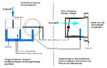
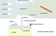
Carburetors work on the principle of the Venturi nozzle . The hydrodynamic pressure at the narrowest point of the air funnel increases with the flow, the static pressure decreases accordingly. This pressure difference sucks the fuel, which is kept at a constant level in the float chamber, through the main nozzle into the air funnel, where it atomizes into an aerosol. The diameters of the air funnel and main nozzle must be designed for the maximum power of the engine, which means that at low speed ( idling ) the vacuum is not sufficient to achieve constant engine running. Therefore, the most commonly used carburetors with constant air funnel cross-section have their own idle and transition system.
It was recognized early on that the diameter of the air funnel and main nozzle would have to be variable in order to guarantee the optimal combustion air ratio for every load condition. In particular, engines with a larger displacement have been given so-called register or “stage carburettors”, in which an additional air funnel with a larger cross-section is activated depending on the load and speed.
The second solution is the so-called constant pressure carburetor . By means of a vacuum-controlled slide, the suction cross-section and - via a nozzle needle located on the slide - the main nozzle are increased at the same time with increasing flow. The flow velocity in the carburetor is therefore constant, but the piston valve, which is oil-dampened in some designs (e.g. Stromberg carburetors), delays the reaction to the changed load condition.
In the course of the stricter emissions regulations from the mid-1980s, it was no longer possible to find satisfactory solutions for optimal mixture preparation using carburettors. The increasing demands on the exhaust gas quality, which could only be met with catalytic converters and lambda control , required electronically controlled carburetor systems (“ Ecotronic ”) that came close to the complexity of electronic manifold injections. These therefore replaced the carburettor in vehicle construction in the 1990s.
First carburetor
The first carburetor was the surface carburetor developed by Carl Benz . The fuel is evaporated in a heated container and mixed with air. Another design was the brush carburetor invented by the German-Austrian technician Siegfried Marcus . He atomized the fuel in a tub with a rotating brush.
Both do not automatically maintain a certain air ratio, but have to be readjusted depending on the speed or when the load changes. These types of carburetors were only used for a short time in the first internal combustion engines due to their unreliability and danger (carburetor fire).
The Hungarians Donát Bánki and János Csonka first developed and patented the so-called Bánki-Csonka engine in 1893 and, as part of it, a carburetor.
These first designs were replaced from 1893 by carburettors with a float chamber ( spray nozzle carburetor ). Its invention is attributed to Wilhelm Maybach . The first float carburetors were often ascending flow carburetors. Due to the fluctuating quality of the fuels, there was often overfilling; the engine stopped because the mixture formed was no longer ignitable. With the riser carburetor, the fuel can leak out of the carburetor instead of into the engine.
Different types
When categorizing carburetors, a distinction is made today according to several characteristics:
Direction of the intake air flow
The different directions of flow of the intake air through the carburetor determine which type it is:
- Downdraft carburetor , the air flows from top to bottom.
- Flat or cross-flow carburetor , the air flows horizontally. It is mainly used where a low overall height is important; is also called "horizontal carburetor".
- Slanted- flow carburetor , the air flows diagonally from above.
- Riser flow carburetor , the air flows from bottom to top, often also called "vertical carburetor ".
Number and function of the mixing chambers
- Single carburetor - an air funnel
- Double carburetor - two single carburetors in one housing (e.g. BMW 1602/2002 ti with two Solex double carburetors)
- Triple carburetor (until 1973 in various Porsche 911 ) or quadruple carburetor. These types of carburetor use a float chamber, which is usually located in the middle, to supply several suction pipes.
- Register or stage carburetor. One air funnel for idle / part load and one for full load (not to be confused with double carburetors).
- Double register carburetor (two register carburetors in one housing): in the Mercedes-Benz 280 ( W 114 ), the 250/280 of the W 123 series and the 280 S ( W 116 ), BMW 320/6 from the E21 series , BMW 520 / 6, 525, 528 (without "i") from series E12 .
Type of throttle organ

- throttle
- Slider with the subspecies:
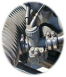
- Piston valve, also called round valve. The piston is pulled up directly using the throttle and Bowden cable (example: BMW R 90 S with Dell'Orto carburetors). A slightly conical nozzle needle in the center of the piston changes the open cross-section of a nozzle and thus controls the amount of fuel. The piston-needle system is supplemented by:
- the main nozzle (this sits at the lower end of the needle system and limits the fuel flow through the needle system)
- the idle jet downstream of the main jet system
- Flat slide valve in the shape of a rectangle with a circular passage. Free installation position and advantageous because, for. B. in racing engines with a slide a whole cylinder bank (three to six cylinders) can be controlled.
- Piston valve, also called round valve. The piston is pulled up directly using the throttle and Bowden cable (example: BMW R 90 S with Dell'Orto carburetors). A slightly conical nozzle needle in the center of the piston changes the open cross-section of a nozzle and thus controls the amount of fuel. The piston-needle system is supplemented by:
Constant pressure carburetor
With the constant pressure carburetor, the negative pressure acting on the main jet system is always the same in static operation at constant speed - hence the name. This is achieved in that (viewed in the direction of flow) a piston valve attached to a membrane is located in the gas flow in front of the throttle valve . The suction vacuum is directed into the space above the diaphragm, which creates a pressure difference to the atmospheric pressure passed through another hole under the diaphragm, which pulls the diaphragm with the piston valve upwards. A conical nozzle needle is attached to it, which controls the open cross-section of the main nozzle and thus the amount of gasoline flowing in.
The constant pressure carburetor controls the amount of petrol depending on the amount of air and independently of the throttle valve position. The carburetors do not need an acceleration pump, because even a quick acceleration does not lead to the gasoline-producing negative pressure collapsing. Rather, the mixture is enriched because the sluggish piston reacts somewhat delayed to the changed load condition and therefore the pressure difference conveying the fuel is briefly higher. On the one hand, the response of the engine is a little slower than with the slide carburetor, on the other hand, the typical hole when the throttle is operated quickly and the slide carburetor is incorrectly adjusted is avoided. The constant pressure carburetor is used particularly in motorcycles (examples: Bing carburettors of the early BMW R 75/5 models, numerous Japanese machines with Keihin and Mikuni carburettors and Ducati models up to 1999).
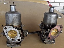
Various Mercedes-Benz cars built between 1965 and 1985 ( W 115 , W 123 and W 201 series ) were equipped with Stromberg constant pressure carburetors. SU carburettors ( Skinner Union ) based on this principle were also used in many British automobiles and at Volvo .
Constant pressure carburetors continued to be common in numerous motorcycle engines since the 1970s and are still used in some cases today; while the majority of models today use injection.
Special designs
Initially with aircraft engines , the need arose to use carburettors that fulfill their function regardless of the position in space, especially when the aircraft rotates ( centrifugal force ) and “overhead”. There have been a number of developments for this; one of the best known is the membrane carburetor . The same problem arises with small engines, for example in gardening tools ( lawn mowers on steep slopes) or with chainsaws , where the position of the carburetor should not have any influence on the engine running. In some cases, such carburetors were also used in conventional motor vehicles, such as the Tillotson diaphragm carburetors on Harley-Davidson motorcycles .
There is also the overflow carburetor, which works without a float chamber. That is why it is particularly cheap to manufacture and simple to build. With it, the fuel is pumped from the fuel tank below the carburetor into a very small fuel reservoir, from which the mixture formation nozzle is operated. The fuel that is pumped too much into the reservoir then returns to the fuel tank by gravity. This type of carburetor was z. It was used, for example, in the “ Vélosolex ” moped and until 1967 in the first Porsche 911 .
In the Fish carburettor (after John Robert Fish), the float chamber is connected to the hollow throttle valve shaft, on which the fuel flows out through bores.
If an engine is equipped with several carburettors, these should be synchronized. See: Synchronization # Carburettor synchronization
Additional equipment
Cold start aids
Swab or primer
A cold start aid can often be found on simple carburetors as a "swab" or "primer". The swab is a pin on the float chamber cover which, when activated, pushes the float downwards and thus opens the float needle valve. The float chamber is flooded with petrol and the mixture is enriched at the start ( combustion air ratio λ <1) so that it ignites better. As a rule, the swab may only be operated briefly for two to four seconds; Too long “dabbing” can flood the entire intake tract with fuel, so that the spark plug gets wet and the engine “drowns”.
Instead of the swab, a rubber bellows (“primer”) can be used, which acts as an air pump and pumps a small amount of air into the float chamber and thus also pushes the float downwards. The primer should be briefly actuated three to five times.
Starter flap (choke)
The choke (engl. Choke) is a device with which enriched the mixture during the start and warm-up phase of the engine, that is "fat" is made. This is done in that a separate flap in front of the throttle valve or the slide achieves a narrowing of the air cross-section; Due to the associated increase in the negative pressure, more fuel is now sucked out of the nozzle and the air flowing through is enriched. Starting without a choke is often not possible, especially when the engine is cold. If you forget to open the choke again after the warm-up phase, this leads to poor engine running and high consumption. To avoid these problems, many vehicles had a control lamp for the pulled choke. As a further development, there was the automatic starter , which activates and resets the choke automatically, partly temperature-controlled (see following section).
Starter carburetor
Another variant is the release of a second, simple, unregulated carburetor system (starter carburetor system) via an airway that bypasses the throttle element and is released at the same time as the starter flap is actuated. This bypass creates a very over-greased mixture in small quantities through its own nozzle, which is added to the finished mixture behind the valve. This type of choke is used e.g. B. used in BVF and Bing series 17 carburetors. Also have been installed millions of times Dell'Orto 's SI and SHB carburettors, specifically for the Vespa designed -Schaltroller downdraft (SI) and Flachstrom- (SHB) flat slide carburetor series.
Automatic start
In principle, the activation of the previously described starter flap is automated here. To get it going, you usually have to fully depress the accelerator pedal once. (There are also fully automatic starting systems, e.g. Pierburg 2E2, which switch on automatically when the engine is cold). The throttle valve is opened and, at the same time, a temperature-influenced bimetal spring closes the starter valve (air valve) initially except for a small gap. If the engine is in operation, a pull-down device (it works with negative pressure) causes the starter flap to open when you accelerate. The bimetallic spring is heated (initially only electrically, with carburettors built from around 1970 also with cooling water circulation) so that the starter flap opens. This takes so long until the engine is at operating temperature (carburetor or water temperature 60 ° C).
Intake air preheating
The preheating of the intake air prevents the carburetor from icing up in cool weather and the engine running irregularly or from dying. This can be prevented by heating the intake duct with cooling liquid and / or an electrical heating element (so-called "hedgehog"). In the simplest version of preheating, the intake air is directed past the hot exhaust manifold. Many vehicles had a manually operated flap for the switchover from summer to winter operation, with others the switchover happened automatically via a thermostat .
Accelerator pump
Most carburetors have an acceleration pump that pumps additional fuel into the air funnel when the throttle valve is opened (enlargement of the intake cross section ) in order to avoid an undesirable "acceleration hole". Otherwise the mixture would become lean due to the drop in the negative pressure at the throttle valve opening. A small piston pump is often used for this purpose, which additionally injects a small amount of fuel into the intake system when the accelerator pedal is pressed. A "nervous foot on the accelerator" causes the accelerator pump to operate continuously, which increases fuel consumption.
Full load enrichment
The highest engine output is achieved with a rich mixture of approx. Λ = 0.85. This is where the highest ignition speed or reaction speed of the gasoline mixture occurs. A separate channel is used for enrichment, through which additional fuel is fed into the air funnel.
The enrichment should also prevent the mixture from becoming too lean when reaching full load (λ> 1) and the combustion becoming too "hot". This could cause a hole in the piston crown, which could seriously damage the engine . The evaporation heat of the additionally supplied fuel ensures "internal cooling" of the cylinders.
Height corrector
The air at higher altitudes contains less oxygen, corresponding to the lower air pressure and thus decreasing density; however, the density of the liquid fuel does not change as a function of the altitude. Since carburetors measure the amount of air and fuel by volume, there is no oxygen for complete combustion at high altitudes without corrective action, so the mixture is too rich.
In rare cases - absolutely in hill climbs - carburetors therefore have an automatic device to compensate for the lower density of the air at higher altitudes. A barometric can changes the mixture formation. This facility was often an option on older vehicles built before 1970. In aircraft with a carburettor engine, the mixture is set manually by the pilot using a mixture regulator ( Leanen ).
Many electronic injection systems, on the other hand, record the air mass sucked in - or calculate the air density from the measured air pressure - and thus switch off this source of error in mixture formation from the outset.
The corrector only ensures that complete fuel combustion can take place at any altitude by setting the mixture formation to the correct value - close to the stoichiometric fuel ratio. It cannot compensate for the drop in performance that occurs when the air density drops, because without charging , only as much fuel can be burned as corresponds to the amount of oxygen in the air.
Partial load enrichment
In order to achieve a low consumption and still have enough power under load, there is the vacuum-controlled partial load enrichment. It is also used to ensure that there is no "hole" when the throttle valve is opened. This also controls the transition from idling to accelerating.
Power jet
The power jet nozzle is used to adapt the mixture in two-stroke engines in the medium speed range. It draws its fuel directly from the float chamber through negative pressure and atomizes it in front of the carburetor slide. The Japanese carburetor manufacturer Mikuni was one of the first in the 1970s to apply the principle of negative pressure directly from the float chamber. This made it possible to make the main jets of the carburettor smaller, which had a positive effect on the response behavior and performance. Today a distinction is made between purely mechanical and electrical systems.
Electronically controlled carburetor system
The electronically controlled carburetor system appeared in the late 1970s. It reduced pollutant emissions and fuel consumption compared to conventional carburetors and was cheaper than an injection system. For a transitional period, electronically controlled carburetors were a popular means of meeting the stricter emissions standards that were gradually being introduced throughout the United States, Switzerland, Germany and the rest of Western Europe, starting from the state of California. In particular, depending on the complexity, they could also be combined with unregulated and regulated catalytic converters . For reasons of cost, automobile manufacturers used such carburettors primarily for the basic engines of the respective series.
Many of the carburetor manufacturers active at the time included electronically controlled models in their product range, including Pierburg , Denso , Hitachi , Holley , Weber and Dell'Orto . They either developed them themselves or used developments under license, especially from well-known market leaders. A relatively sophisticated and successful variant presented the Ecotronic is originally a joint development in a joint venture of the companies Bosch and Pierburg , from the former to retire later.
The heyday of electronically controlled carburetor systems ended around the 1990s: The combination of electronics and mechanics sometimes proved to be prone to defects and maintenance-intensive. The cost advantage of electronically controlled carburettors was reduced as the unit prices of injection systems with ever larger quantities fell. The fuel consumption of the carburettor engines remained mostly higher than that of injection engines and new, stricter emission limit values could no longer be complied with.
literature
- Heinrich Illgen: Carburetor manual: carburettors, fuels, gasoline injection systems, synchronous test devices and fuel pumps. 6th edition. Verlag Technik, Berlin 1977.
- Jürgen H. Kasedorf: Carburetor and catalytic converter technology. Vogel-Verlag, Würzburg 1993, ISBN 3-8023-0460-8 .
- Jürgen H. Kasedorf: Mixture preparation, part 1: Carburetor repair and adjustment: Basics. 4th edition. Vogel-Verlag, Würzburg 1986, ISBN 3-8023-0321-0 .
- Jürgen Kasedorf: Mixture preparation, part 2: Carburetor from Pierburg GmbH & Co. KG (formerly: Deutsche Vergaser-Gesellschaft DVG). 3. Edition. Vogel-Verlag, Würzburg 1987, ISBN 3-8023-0342-3 .
- Gert Hack: make cars faster. 11th edition. Motorbuch-Verlag, Stuttgart 1980, ISBN 3-87943-374-7 .
- Jan Drummans: The car and its technology. 1st edition. Motorbuch-Verlag, Stuttgart 1992, ISBN 3-613-01288-X .
- Hans Jörg Leyhausen: The master craftsman's examination in the automotive trade. Part 1. 12 edition. Vogel Buchverlag, Würzburg 1991, ISBN 3-8023-0857-3 .
- Peter Gerigk, Detlev Bruhn, Dietmar Danner: Automotive engineering. 3. Edition. Westermann Schulbuchverlag, Braunschweig 2000, ISBN 3-14-221500-X .
Web links
- Carburettors on motorcycles
- Carburetor, technical explanation
- Carburetor FAQ
- Single carburetor
- Know-how
- Electronic SU carburetors (English)
Individual evidence
- ↑ a b Solex carburettor type BFH / BFV on ruddies-berlin.de
- ↑ Power Jet ( Memento from March 9, 2015 in the Internet Archive )
- ↑ Dell'Orto p. 27
- ^ Alfred Urlaub: Internal combustion engines. Volume 1: Basics. Springer-Verlag, Berlin a. a. 2013, ISBN 978-3-642-83216-1 , p. 148 ff.


