
Scharfenberg coupling


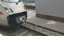


The Scharfenberg coupling ( Schaku abbreviation ) belongs to the middle buffer couplings . It enables trains to be coupled and uncoupled quickly, easily and, above all, safely. The coupling was developed by Karl Scharfenberg in the L. Steinfurt AG wagon factory in Königsberg , who received patents on it in 1904 and 1907 (Reich patent 149727, patented from May 6, 1903 and Reich patent 188845, patented from April 5, 1906).
Today the Schaku is used in all kinds of passenger trains around the world, from trams to high-speed trains, and in almost all state railways. In 2002 the type 10 of the Scharfenberg coupling was declared the standard for high-speed trains and is now part of the Interoperability Specification (TSI).
history
In Germany, the Association of German Railway Administrations (VDEV) was looking for a better coupling as early as 1873 with the following tender: “Because of the great danger to the health and life of officials and railway workers associated with the current coupling, the VDEV will issue a 1. Price of 3000 thalers and a second price of 2000 thalers for the invention of a device by means of which the coupling of the railway wagons can be carried out without the intervention of the worker performing the coupling between the wagons. "
However, no satisfactory offers were received for this tender. No coupling could be found in Germany that met all the requirements of the VDEV. This was only to change in 1903. On May 6, 1903, Karl Scharfenberg applied for a patent for a “central buffer coupling with an eye and a rotating hook as coupling elements”. At that time hundreds of patents were pending on automatic clutches.
His coupling was first used in 1908 on the private Memel small railway , where it proved itself. In 1926 the Deutsche Reichsbahn registered interest and installed Scharfenberg's coupling on a trial basis in some large-capacity freight wagons that operated on the coal shuttle service to the Klingenberg power station in Berlin. However, this approach was not followed up.
In 1921 the Scharfenberg-Kupplung AG, based in Berlin, was founded by the wagon construction company Steinfurt in Königsberg and the Busch company in Bautzen . It was determined that the heavy couplings for trains should be built in Königsberg and all other couplings, for example for trucks, in Bautzen. In collaboration with several electrical companies, including Siemens and Brown Boveri , an improved coupling was developed that could also be used to connect electrical lines. Previously, the electrical lines had to be plugged in by hand. The brake air lines could now also be connected automatically.
Since the American Willison coupling had not proven itself in the suburban trains of Berlin (forerunner of the Berlin S-Bahn ) , they were looking for a better coupling and decided to introduce the Schaku. In 1924 the Berlin U-Bahn also introduced the Schaku with the U-Bahn type BI, and a little later the U-Bahn in Buenos Aires (Argentina). The first full-line vehicles that ran on the tracks of the Deutsche Reichsbahn with the Schaku were the diesel express railcars and the Henschel-Wegmann train , which could reach a speed of 175 km / h with its steam locomotive.
After the Second World War, Scharfenberg AG moved its headquarters to Salzgitter . After several changes of ownership, the Voith Group finally took over Scharfenbergkupplung GmbH & Co. KG in 1998 . Today the Scharfenberg couplings are offered by Voith Turbo GmbH & Co. KG.
The spread of the shaku has increased sharply in the last few decades. In 1935 only 20,000 clutches were installed in Europe, in 2004 there were already more than 250,000.
Although the coupling principle is the same for all Scharfenberg couplings, there are different coupling types depending on the application. The type 10 of the Scharfenberg coupling has proven itself especially in full-rail multiple units, also in high-speed traffic, and in 2002 it was declared the standard coupling for high-speed trains. Smaller types are mainly found in underground vehicles and trams. The different types are not compatible with each other.
Working principle
The Scharfenberg coupling is a rigid central buffer coupling. The connected domes form a rigid connection. This coupling enables electrical and pneumatic connections to be coupled. To compensate for relative movements between the coupled vehicles, the couplings are pivoted vertically and horizontally in the floor frame.
Adjustment lock

Schematic representation of a clutch assembly
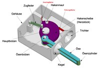
Individual parts of a Scharfenberg coupling

Blocking at different radii
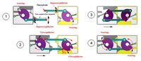
Coupling process with a Scharfenberg coupling

Forces with a coupled Scharfenberg coupling
A coupling assembly is shown schematically in the picture. The transfer of impact and tensile forces to the car body (frame) of a rail vehicle takes place via a so-called linkage (see e.g. deep linkage ). The coupling head containing the actual coupling is connected to this via shock absorption (or else rigidly). The linkage can be rotated horizontally and vertically in relation to the vehicle and moves accordingly when cornering or when transiting inclines. Usually, the linkage is provided with a central adjusting device which tries to keep the coupling assembly in a central position in the uncoupled state and tries to return it to this position when it is deflected by restoring forces.
The mechanical connection principle is characteristic (and eponymous) for the coupling. The couplings for the pneumatic and electrical connections are assigned to this in various variants.
The coupling head is provided with a cone and a funnel, which are joined together with the corresponding parts of the mating coupling during coupling and thus lead to an alignment of the two coupling heads with one another. An eyelet protrudes from an opening in the cone and dips into an opening in the funnel of the mating coupling.
A main bolt is fastened in the housing of the coupling head, on which the hook washer (frog) is rotatably arranged (see picture). The hook washer carries the eye bolt around which the eye can rotate. The hook mouth (open slot) is located in the hook disc. The central axis of its (cylindrical) rounded surface is offset by 180 ° on the same radius as the eye bolt (relative to the main bolt). This is absolutely necessary, because with different radii of the eye bolts and hook jaws, the hook disks connected by the eyes would block each other and no movement would be possible (small differences due to manufacturing technology are compensated for by the corresponding play of the paired parts). The movement of the eye bolt of a hook washer through an angle α must be opposed to the same angular movement of the other hook washer. This is not the case with different radii (see picture).
A tension spring pulls the frog against a stop surface on the housing (position ready for coupling). The eyelet cylinder engages in the hook mouth of the mating coupling when coupling.
The opening in the cone of the housing is provided with boundary surfaces within which the eyelet can move (see picture). The eyelet can also be in constant contact with a boundary surface through structural measures (e.g. spring force).
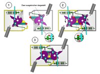
Position (1) shows the coupling and mating coupling of the two vehicles to be coupled in the position ready for coupling. When the clutches move together, both eyes meet the respective hook disk of the other clutch and are prevented from moving further by the forces F1 (hook disk) and F2 (guide surface) (position (2)). When moving closer together, the eyes twist their hook washers (against the force of the respective tension spring). This achieves a position in which the eye cylinders slide into the corresponding hook mouth of the hook washer (position (3)) and the funnel and cone of both couplings are joined together. The eyelets are no longer blocked and the hook washers twist due to the spring forces acting on them up to their stops (position (4)), whereby the eyelets are moved into their coupling position. This is done with a quick (snap) movement. It should be noted that the clutches are not braced against each other, but only transferred into a non-detachable position. The connection is therefore not free of play . This results from the fact that for a jam-free coupling the respective hook mouth has to be slightly larger than the engaging eye cylinder and the distance between the eye cylinder and the eye bolt must be greater than the distance between the main bolts in the closed state (see animation). However, the play is relatively small, so that the coupling connection can be regarded as rigid and only the two articulations twist when cornering.
The strength of the tension springs has no influence on the strength of the coupling connection. The force of the spring only needs to be measured in such a way that it can safely turn the associated hook washer and the eye into the required position.
The coupling connection shown is an adjustment coupling (adjustment lock), since the hook washers are in the same position (adjacent to their stops) when they are ready for coupling and when they are coupled.
The coupling connection cannot be released by tensile and compressive forces (impact forces) (see picture). The tensile force Fz is distributed equally over the eyelets. The two torques M and -M are generated on the hook disks, which mutually cancel each other out and thus cannot lead to any twisting of the hook disks which releases the coupling. The pressure force is absorbed by the conical and funnel surfaces of the two housings.

Uncoupling a Scharfenberg coupling

Coupling misalignment (borderline cases)

Coupling alignment
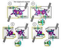
In order to release the coupling connection, one of the two hook washers (the other then moves accordingly) must be turned from position (4) to position (3). Then the vehicles can drive apart. The rotation is mostly done pneumatically (piston rod of a pneumatic cylinder acting on the hook disk ) or manually (pull rod, pull rope), rarely electrically. In order to avoid that the opening force has to act until the vehicles are separated, the hook disc can be rotated to a stable locking position and remain in this position without any further application of force. The vehicles can then move apart at a later point in time. The picture shows a schematic version with a manually operated pull rod. The coupled position (4) is first transferred to position 5 by pulling the pull rod 2. By further pulling the eyelet cylinder of the eyelet of the hook disk 1 gets into a prismatic recess of the hook disk 2 and is blocked there by the forces Fk1 (guide surface) and Fk2 (hook disk) (position (6)). The hook disk 1 can therefore not be rotated by the spring force acting on it. The hook washer 2 cannot rotate either, since the eyelet cylinder acts on it with the force Fk3. The eye of the hook washer 2 has come loose from the hook washer 1. This position does not offer any resistance to the vehicles moving apart. The couplings then snap back into their positions (7) ready for coupling. By pulling the pull rod 1 instead of the pull rod 2, the coupling would have been decoupled in the same way. The locking position is implemented in a wide variety of constructive ways.
The eyelet protruding far from the coupling head represents an obstacle for the automatic joining of the couplings (if the coupling ensembles are not exactly aligned). Modern designs have only a few eyelets protruding from the cone (see picture). According to, four borderline cases of clutch misalignment are to be distinguished (central adjustment device required). To ensure that the couplings come together in all cases, the coupling heads are provided with guide horns (seldom above and below). These are particularly important in the case of couplings without a central adjusting device, in which the coupling takes place in any deflected (but narrowly limited) position of the articulations. Two borderline cases are shown in the picture, whereby the guide horns are only effective in one. The guide horns slide on each other when they move together and, due to their inclination, twist the linkages into a position that can be coupled.
Two-position lock
Two-position lock (overview)

Two-position lock (individual parts)
Two-position lock (domes)
Two-position lock (uncoupling)
With the two-position lock, the ready-to-couple and the coupled position differ. The function is again explained below with the aid of schematic diagrams. Animations of realized constructions can be found under.
With the adjustment lock, the eyelet cylinders hit the hook washers of the counter-coupling when the vehicles move together and then move against each other by friction until the eyelets slide into the respective hook mouth. With the two-position lock, each eye cylinder is guided directly into the hook mouth of the counter-coupling when it closes and then moves in the same direction of movement into the coupled position. This makes coupling smoother and reduces wear on the couplings. The locking principle (moment equilibrium on the hook washer) corresponds to that of the adjustment lock.
In contrast to the adjustment lock, the hook washer (centerpiece) is provided with a swiveling ratchet rod. In the ready-to- connect state, a detent on the latch rod engages under a stop 2 located on the housing (position (1)). The tension spring can thus not twist the hook disc. This position is secured by a resilient plunger which presses the ratchet rod against a stop 1 also located on the housing.
When the vehicles come together, a switch nose formed on the cone of the respective counter-coupling presses on a resilient plunger and moves it (position (2)). The stamp has a slide which presses against the latching lug of the ratchet rod so that it leaves the latching surface of the stop 2. The hook disc can now turn (driven by the tension spring) until its stop finger rests against the disc stop on the housing. This is the coupled position (3) in which the respective cones and funnels of both couplings lie one inside the other.
As with the adjustment lock, uncoupling can be done manually, pneumatically or electrically. A pneumatic variant is shown in the picture. The piston rod of one of the two pneumatic cylinders presses on the opening arm of the hook disk and rotates it against the force of the tension spring. The ratchet rod slides over the stop 2 thanks to the bevels attached to the stop 2 and the detent lug and reaches a detent position, the plunger pushing the lug into this position. However, the latch now does not engage under the stop 2, but under the latching surface of the ram slide (position (4)). Due to the loop coupling, the hook washer and the ratchet rod of the counter coupling move in the same way. The piston rod can now be moved back. This position does not prevent the two vehicles from moving apart.
When the vehicles move apart, the ram is released and moved by its compression spring, with the locking surface of the slide leaving the locking lug of the ratchet rod (position (5)). The hook disc rotates a little until the locking lug rests against stop 2. The position (1) ready for coupling is reached again.
The latch bar protrudes from the housing. This enables manual emergency opening by pulling the rod into position (4).
Structure, assemblies and technical data
When two vehicles with Scharfenberg couplings drive together, the couplings are firmly connected to one another. They form a rigid connection through which tensile and compressive forces are transmitted, so that they do not rock and cannot climb when coupling. To ensure that passengers have a smooth journey and that goods and vehicles are not damaged, shock absorbers can be attached to the coupling, which absorb the forces like shock absorbers on the car. The guide horn, which is available on many Scharfenberg couplings and is attached to the bottom of the coupling, roughly aligns the couplings with one another so that you can also couple in curved tracks and on uneven tracks. Some couplings allow an offset of up to 370 mm horizontally and up to 140 mm vertically. The fine tuning is done via the cones and funnels , which fit perfectly into each other, so that the couplings are exactly against each other. The connection is made via the dome lock.
What is special about the principle of the Scharfenberg coupling is that there is no coupling lock with a detent, as is the case with the Russian SA 3 or the American Willison coupling. The transmission of the tensile forces takes place solely through the balance of forces between the two coupling eyes via the frog and the main bolt. When uncoupling, no detent is disengaged, but only the frog is rotated against spring force, which releases the coupling eyes from the mouth of the opposite coupling. Only the actuation of electrical couplings that are sometimes present on the Scharfenberg coupling is locked. The uncoupling process can be done pneumatically from the driver's cab, less often electrically. In any case, however, manual disconnection is possible (emergency disconnection in the event of a fault).
Some couplings can withstand a compressive force of over a thousand kilonewtons without damage. These enormous forces only arise in the event of an accident and not during operation; significantly lower tensile and compressive forces (when starting or braking) occur here. In the case of smaller vehicles, the energy consumption is even lower due to the lower vehicle mass, which also results in only lower forces.
Most modern Schakus can be heated, as reliable operation is not possible when iced over.
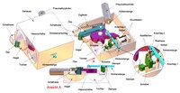
The Scharfenberg coupling has a modular structure so that it can be adapted to different requirements. It consists of a head area and the linkage.

Head area
The head area is the front part of the coupling (blue in the diagram). It creates a pneumatic, electrical and mechanical connection between the carriages. When coupling, first mechanical and pneumatic coupling is carried out, then the electrical connection is established.
The head area usually comprises the following components: coupling lock, air line coupling, electrical coupling and decoupling device.
Coupling head with coupling lock
The coupling lock connects the two vehicles mechanically. The coupling head is designed so that it has as large a gripping area as possible in which automatic coupling is possible. The gripping area is enlarged by a gripper located at the bottom of the coupling. This means that the couplings can also be coupled in curves and when there are differences in height. The gripper roughly guides one coupling to the opposite one, the rest is then taken over by the cones. These lie exactly in the funnels of the opposite coupling, creating a form-fitting connection. This is a prerequisite for coupling the pneumatic and electrical lines. The connection has little play, which minimizes wear.
When establishing the mechanical connection, a distinction is made between the one-position lock and the two-position lock.
Adjustment lock

The adjustment lock has only one position. The coupling eyes have the same position in the coupled as well as in the uncoupled state. The movements during the coupling and uncoupling process, in which the eyes and frogs turn into one another, are not regarded as an additional position. At the beginning of the coupling process, the coupling eye is on the edge of the cone. The frogs are pressed against a stop by springs so that they are always correctly aligned.

By moving the couplings together, the locks are turned against the force of tension springs until the coupling eye of one coupling engages in the hook mouth of the heart of the other coupling. Once this has happened, the locks are turned back in the other direction by the force of the tension springs until the forces are balanced. The coupled position has been reached and the two couplings are now firmly connected to one another

When uncoupling, the locks are turned against the force of the tension springs until the coupling loops slide out of the frog mouths. A coupling loop engages in a recess behind the frog mouth. This prevents the coupling loops from locking into the frog mouth again. If the couplings now move apart, the coupling locks turn back again under the force of the tension springs, and the position ready for coupling is restored.
Two-position lock


In contrast to the adjustment lock, the two-position lock differs between the ready-to-couple and the coupled position. When the coupling is ready for coupling, the coupling locks are turned so that the coupling eye is on the edge of the cone. The frogs are held in their position by the ratchet rods that protrude laterally from the coupling head housing and are locked into the punch guide. Before the end faces (these are the surfaces on which the couplings lie against one another) meet, the cones push the punches back in the funnel opposite. The punches press against the locking of the ratchet rods, which loosens and releases the lock. The locks are turned by the force of the tension springs. The dome loops grab into the frogs. In their end position, the closures are in an equilibrium of forces. The coupled position has been reached. For uncoupling, the frogs are turned against the force of the tension springs until the coupling eyes slide out of the hooks' mouths. In this position, the ratchet rods fix the locks as they snap into the punch guide. In this way, the clutch is again in the ready-to-couple position after the vehicles have been separated.
Air line coupling
The vehicles are pneumatically connected to one another via the air line coupling. Compressed air is transmitted through the air lines for braking and other purposes. The lines are always on the face and mostly between the cone and the funnel. The mouthpieces of the lines always protrude a little and are pressed onto the mouthpieces of the other coupling when coupling.
There are three types of air line couplings that can be present on a coupling: the main air line (HLL), the main air reservoir line (HBL) and the decoupling line (EL).
Main air duct

The main air line (HLL) carries the compressed air to the brake control . There is always pressure on this line; as soon as a pressure drop occurs, braking occurs.
The air line coupling for the main air line is attached in the upper part of the face. The mouthpiece (see picture on the left), which connects the two air lines, protrudes a few millimeters from the face. The two mouthpieces are pressed firmly against each other by springs when coupling, so that no air can escape.

Example with a two-position lock: The air line coupling for the main air line has a valve that is controlled by the main bolt of the dome lock. When coupling, the bolt rotates, which releases the valve and is pressed down by springs so that the compressed air can flow through it.
When the couplings are separated again, the bolt also turns back, which also closes the valve again, so that no more air can flow through. This prevents air from escaping when no other coupling is connected; Otherwise the train could no longer run due to the applied brakes.
Main air receiver line
The main air reservoir line (HBL) carries compressed air for all connected consumers, for example door closing devices or air flaps. The air for uncoupling is also provided here.
The coupling for the main air tank line (HBL) is located behind the face under the coupling for the main air line (HLL).
The mouthpiece of the line, like the mouthpiece of the main air line, protrudes a few millimeters from the surface. The air coupling for the main air tank line has a spring-loaded valve stem. In the uncoupled state, a valve is pressed against a stop by the springs and ensures that no more air flows through it. When coupling, the two valve tappets of the air couplings are pressed against one another and thus pushed backwards against the force of the springs, which releases the line for the compressed air.
Decoupling line
The decoupling line (EL) carries the compressed air that is necessary for the automatic decoupling of the Scharfenberg couplings.
The air line coupling for the decoupling line is accommodated in a housing with the coupling of the main air tank line and receives the air from this to carry out the decoupling process.
The air line coupling for the decoupling line only carries air when the Schaku is decoupled, which is why it does not have a complete coupling like the main air and main air tank line, but is simply sealed off by pressing two rubber pipes together during the coupling process.
Electrical contact coupling


The electrical coupling couples the electrical lines, such as control lines or power lines for light and other loads. The arrangement, size and control of the electrical coupling depends on the vehicle and the number of electrical lines that are to be coupled.
In the uncoupled state, the contacts are protected from dirt and moisture by a protective flap and pulled back behind the level of engagement. When two vehicles drive together, the contact attachments are automatically brought into the coupling position, and the protective flaps open automatically. The contact attachments are pressed against each other and the contacts are connected to one another.
Electric couplings are differentiated according to their position, the type of contacts and the actuation. Originally, such as the railcar of Berlin and Hamburg train and the speed railcars the German Railway and their successors, the contact towers were installed on top of the coupling heads. Changes were made in connection with the requirement for intercar crossings . For a smooth transition, the contact attachments had to be relocated to the sides of the dome heads. Another possibility is the location under the dome head. It is used, for example, in subway and tram cars. In the case of the latter, this position allows unused couplings to be designed to be foldable. There are also different types of contacts for the electrical lines. Depending on whether the cables are used for power transmission or for control, the cables can transmit currents of up to 800 A.
The first demonstrable use of Scharfenberg couplings with contacts took place in 1932 on the Zwickau tram.
Linkage
The rear part of the coupling is referred to as the linkage (red in the diagram). It can be constructed differently depending on the task at hand and consists of a shock protection device, a pulling and shock device and, if necessary, a central positioning device.
Shock protection
The shock protection is located in the coupling rod. It protects the vehicle and the passengers from damage if the approach speeds are too high. Depending on the vehicle, weight and setting, collision speeds of up to 20 km / h can be withstood without damage to the vehicle.
There are two ways to absorb the power: destructive and regenerative .
Deformation tube

The deformation tube works destructively, which means that once the force has been absorbed, it cannot be used again but must be replaced. It consists of two tubes, one slightly thinner than the other. It does not fit into the larger pipe by itself. If a great force is now applied, the thin tube pushes itself into the larger tube, which has to expand and deform. A lot of energy is absorbed here.
Hydrostatic buffer

The hydrostatic buffer works regeneratively, which means that it is not damaged when it is deformed and can therefore be used again after stress.
Gas hydraulic buffer

The gas hydraulic buffer works like the hydrostatic buffer regeneratively. The buffer consists of a nitrogen -filled plunger and an oil-filled cylinder. When forces occur, the plunger pushes itself into the cylinder, which forces the oil through a small opening and presses itself into the plunger. There is a separating piston between the nitrogen and the oil flowing into the plunger so that the nitrogen cannot mix with the oil. The nitrogen is strongly compressed and builds up a high pressure. When no more force acts on the buffer, no more oil is pressed through the opening. But since the nitrogen is now under high pressure, it presses the oil back into the cylinder through the opening. The buffer is now back in its original position and the process can be repeated. The gas hydraulic buffer is usually combined with a ring spring to dampen the tensile forces.
TwinStroke

The TwinStroke dampens tensile and compressive forces without an additional functional element. A piston system transfers the tensile and compressive forces on a gas-hydraulic basis to various gas and oil chambers. In this way, almost any load can be absorbed immediately and with little wear. The small size and low weight are advantageous, since only one element is needed to absorb compressive and tensile forces. It is also cheaper than a comparable system with two elements and can be quickly replaced if necessary. The TwinStroke can also cope with changing loads very well.
Pulling and buffing device
The pulling and pushing device is used to absorb compressive and tensile forces while driving and during the coupling process. These include the elastomer spring joint, the steel friction springs and the hollow rubber springs.
Elastomer spring joint

The elastomer spring joint (EFG) consists of a bearing block and a spring joint, which is mounted in the bearing block so that it can move horizontally and vertically. This is necessary because the Scharfenberg coupling, in contrast to the screw coupling, is firmly connected. If the coupling were not to be moveable, you would have a stiff train that could not negotiate curves or changes in incline. The spring apparatus consists of the upper and lower shell, the elastomer spring parts and the center piece. The spring parts are inserted without play in the upper and lower shell and fixed with the middle piece.
The spring device is pivoted horizontally in the bearing block. If a force now acts on the center piece (pressure or tensile force), the shear forces of the elastomer spring parts compensate for these forces. If the force is too high, the center piece hits the edge of the housing so that the spring parts cannot be overstretched.
Further development of the EFG as a tear-off solution
The EFG is attached to the vehicle chassis using screws. If you use shear bolts, they will shear off if the load is too high and the coupling is pushed under the car body . This will prevent further damage to the vehicle.
Steel friction spring
The steel friction spring is located in the coupling rod, which is used to absorb tensile and compressive forces. There are alternating small and large steel rings in the spring. When a compressive force is applied to them, the small rings compress and the large ones expand a little so that they can slip together. When there is tensile force, the individual elements are pulled apart. This spring is usually combined with a buffer to absorb larger compressive forces.
Hollow rubber spring

The hollow rubber springs are attached in front of and behind the base plate, which is attached to the vehicle. They used to be hollow, but most of the time they aren't anymore. They sit on the coupling rod on both sides of the base plate. On the other side there are spring plates that prevent the springs from slipping off the coupling rod. When a pressure load acts on the construction, the springs in front of the base plate compress and the rear ones relax. With a tensile load it is exactly the opposite. The hollow rubber springs also allow horizontal, vertical and rotational movements up to a certain angle.
The elastomer spring linkage
The elastomer spring linkage (EFA) is a new variant of the previous rubber hollow spring linkage. In contrast to this, the spring elements here are angular and thus also automatically secure the coupling against twisting.
Central control device
The central adjusting device is used to hold the uncoupled coupling in the correct position and to prevent uncontrolled pivoting. It can be attached below or above the bearing block.
There are three types of center actuators: mechanical, pneumatic and electrical. The mechanical is always in operation, regardless of whether the clutch is coupled or not. The pneumatic and also the electrical central control device are only in operation when the coupling is not coupled; as soon as it is connected, it is switched off.
The functions of the three types are similar. With the mechanical and electrical central positioning device, the coupling is centered by springs, with the pneumatic one by compressed air.
SchaKu variants
Depending on the requirements placed on the coupling, there are different types that are more compact or can transmit more power, depending on the application in which the coupling is to be used.
Type 10
The type 10 can be found on almost all state railways worldwide and is also used in the high-speed range. This type of coupling is particularly characterized by its high strength and the large horizontal and vertical gripping area. It can transmit a compressive force of up to 1500 kN and a tensile force of up to 1000 kN. The coupling heads contain two installation positions for compressed air connections and an additional one for the uncoupling line. The most important dimensions of this type have been defined in the EN 16019 standard since 2014. According to the European Technical Specifications for Interoperability (TSI), high-speed trains are to be equipped with this type of high-speed train at both ends. The coupling is to be installed at a height of 1025 mm above the upper edge of the rail (SOK). In older versions of the TSI (2002/735 / EC and 2008/232 / EC, Annex K) the dimensions of the coupling were still included directly; in newer versions, reference is only made to the EN 16019 standard.
Type 35
The Type 35 is particularly suitable for all-electric vehicles , i.e. vehicles that do not have a compressed air system and only control everything electrically. It is mainly used in regional and metro vehicles. Examples can be found in Shanghai , Singapore , on the Salt Lake City light rail system, and in Calgary . Type 35 can transmit a compressive force of up to 1,300 kN and a tensile force of up to 850 kN.
Type 330
The type 330 is very versatile. It is also preferred in Metro and Lightrail vehicles and offers a high degree of strength despite its small dimensions. In addition, with this type you can arrange the electric coupling under the head to equip narrow vehicles with it. A double-articulated coupling has even been developed for the particularly narrow and curved Avanto tram in Paris. The coupling is uncoupled behind the bow flaps; if these are moved upwards for coupling, the coupling will automatically fold out into the coupling position. The type 330 can transmit a compressive force of up to 800 kN and a tensile force of up to 600 kN and has a large gripping area even without a gripper.
Type 430
Type 430 is a particularly lightweight design for low-floor trams and people movers . Like the Type 330, they can also be folded in to hide them behind the front flaps. It is used, for example, on the trams in Berlin and at KL Rapid in Kuala Lumpur and can transmit compressive and tensile forces of up to 300 kN.
Close couplings
Scharfenberg close couplers create a permanent, rigid connection between intermediate cars in multiple units. The two close coupling halves are connected by means of shell sleeves that can be easily detached from each other if necessary. Since this does not have to be coupled or uncoupled during operation, no automatic system is required. Nevertheless, there is a high level of safety, as these close couplings can also be equipped with shock absorbing elements as well as with electrical and pneumatic couplings. You can also equip them with a support device for the vehicle transition.
Special couplings
Type 55
The type 55 is a special coupling for the Unimog . This type is particularly adapted to a rough work environment.
Type 140
The type 140 is designed for freight wagons and industrial railways. It is suitable for extremely high loads in harsh environments, for example in coal and ore transport wagons, chill and steel casting wagons and in vehicles for the transport of pig iron. This type can transmit a compressive force of up to 2,500 kN and a tensile force of up to 1,500 kN.
distribution
Trams


The Scharfenberg couplings initially only spread slowly among tram operators. It was not until the large-capacity and articulated vehicles of the 1950s that their area of application expanded significantly in Germany. In the GDR , a slight modification of the Scharfenberg coupling with a two -position lock was used to develop the standard tram coupling ( ESW coupling ), which is almost identical to the original, but cannot be coupled with it due to a slight thickening of the coupling cone.
Standard gauge railways
Scharfenberg couplings have long been used in German railways in S-Bahn traffic and in railcars in local and long-distance traffic. This also includes all ICE trains (on the ICE 1 only as an emergency coupling for towing). As a result of the vehicle differences, the various Scharfenberg coupling models can be coupled more frequently mechanically and pneumatically, but mostly not electrically. A special feature was the five-part Henschel-Wegmann train of the Deutsche Reichsbahn , which - like the associated steam locomotives of the DR class 61 - was equipped with Schakus. Likewise the HL-Schnellverkehr on the Lübeck-Büchener Eisenbahn with the streamlined steam locomotives ( series 60 ) and the double-decker cars .
Narrow-gauge railways

One of the first narrow-gauge railways to introduce the Scharfenberg coupling in Germany was the Casekow – Penkun – Oder small railway . It converted its vehicle fleet as early as 1914. Scharfenberg couplings with adjustment locks were introduced on a larger scale in the 1930s as a semi-automatic coupling system on the 750 mm narrow-gauge railways in Saxony . They gradually replaced the previously used funnel couplings . In order to be able to continue to couple vehicles with Scharfenberg and funnel couplings with one another, adapter heads and a uniform coupling pocket have been introduced for new vehicles. A Scharfenberg or a funnel coupling head can optionally be placed on its pivotable shaft, which is guided laterally by the respective bogie in bogie vehicles. The narrow-gauge railways in Saxony that are still in operation today use the Scharfenberg coupling, except for a few vehicles that have been preserved in museums, but only as a mechanical connection. Electrical, brake and heating couplings must be coupled by hand. The Schaku was also introduced for the electric meter- gauge railways in the Rhine-Neckar area ( Oberrheinische Eisenbahn-Gesellschaft AG / Rhein-Haardtbahn GmbH); the vehicles have a tram-like character.
Examples of railway vehicles with Scharfenberg couplings in Germany


S-Bahn traffic
- Series 420 , 422 , 423 , 430 in Munich , Stuttgart , Rhine-Ruhr and Frankfurt am Main
- Class 424 in Hanover
- Class 450 in Karlsruhe
- Series 470 , 471 , 472 , 474 and 490 in Hamburg
- Series ET 165 (275, 475) , ET 166 (276, 477) , ET 167 (277, 477) , ET 168 , ET 169 , ET 170 , 276 (476) , 480 , 481 , 485 , 488 in Berlin
- Multi-system multiple units of the Saarbahn
Regional traffic
- Series 425 , 426 for electrically operated regional trains similar to S-Bahn
- Stadler Flirt (series 427 and 428) for fast regional traffic
- Series 440 and [Series 1440] (Coradia Continental) for regional traffic
- Class 442 (Talent 2) for regional traffic
- Class 445 (Stadler Kiss) for regional traffic
- Class 445 and 446 ( Bombardier Twindexx Vario) for regional traffic (only driver's cabs of the railcars)
- Series 610 , 611 , 612 ( Pendolino or RegioSwinger tilting train )
- Series 613 ( ITINO )
- Series 620, 622, 640, 648 (LINT regional multiple unit)
- Class 642 (Desiro regional multiple unit)
- Series 643, 644 (Talent regional multiple unit)
- Class 646 (regional multiple unit GTW 2/6 )
- Class 650 (regional multiple unit Stadler Regio-Shuttle)
- Class 654 (regional multiple unit RegioSprinter of the Vogtlandbahn )
- Series 771 + 772 ( Deutsche Reichsbahn )
- Integral S5D95
Long-distance transport
- Henschel-Wegmann train of the Deutsche Reichsbahn with class 61 steam locomotives
- Series 401 ( ICE 1 - emergency coupling for towing)
- Series 402 ( ICE 2 ), 410 ( ICE S )
- Series 403 ( ICE 3 ), 406 (ICE 3M)
- 407 series ( Velaro D )
- Series 411, 415 ( ICE T )
- Series 412 ( ICE 4 )
- Series 605 ( ICE TD )
- Class 601 ( Deutsche Bundesbahn )
- Class 175 ( Deutsche Reichsbahn )
- Thalys PBKA
Scharfenberg couplings in Switzerland
- SBB RAm TEE I (discarded)
- SBB RAe TEE II (discarded, 1 train preserved as a museum)
- Bombardier multiple unit NINA (BLS, TRN, TMR)
- Bombardier Lötschberger multiple unit (BLS)
- Martigny-Châtelard railway of the Transports de Martigny et Régions ( meter gauge )
literature
- Kurt Beier, Peter Falk, Herbert Lindinger, Klaus Potschies, Helmut Sauer: S-Bahn Berlin - The new multiple unit ET 480 , Hestra-Verlag, Darmstadt, 1990
- Michael Braun: Karl Scharfenberg, a pioneer in the field of railway couplings, railway engineer, 05/2003, p. 106f.
- Erich and Reiner Preuß: Lexicon of inventors and inventions railways , Berlin, 1986
- K. Sieper: The "Schaku" turns 100 , bus stop, club magazine of the Bergische Museumsbahnen e. V. Wuppertal, 03.2003
- Patent specification , patent number 149 727, Berlin, January 13, 1905
- Peter Falow: Hamburger Blätter - For all railroad friends , 04/2004
- Ralf Roman Rossberg : History of the Railway , Künzelsau, 1977
- Scharfenbergkupplung GmbH, Salzgitter-Watenstedt: 50 years of Scharfenbergkupplung , published on the occasion of the 50th anniversary of Scharfenbergkupplung GmbH, Salzgitter-Watenstedt, November 1971
- Tristan Micke, Wolfgang Dath: Safe, quick and briefly connected , Verkehrsgeschichtliche Blätter , 03–04 / 2003
- Voith Turbo: Scharfenberg Frontsysteme , information booklet
- Voith Turbo: Scharfenberg clutch one4 - top-class maintenance , information booklet
- Voith Turbo: Scharfenberg - Systems , information booklet
- Patent DE149727 : Central buffer coupling with eyelet and rotatable hook as coupling links . Published March 18, 1904 .
- Patent DE188845 : Railway central buffer coupling with double eyelet and rotatable hook. Published August 6, 1907 .
CD
- Scharfenberg GmbH and Co. KG: Schaku Interaktiv , CD, 2000
Web links
- Voith Turbo: Scharfenberg coupling. (February 11, 2007) Online on the Internet
- Electrical couplings ( Memento from April 30, 2012 in the Internet Archive )
- S-Bahn-Galerie.de: Scharfenberg coupling on the Berlin S-Bahn
- Animation of the Schaku nose cone Talgo 250 (4 minutes)
- Animation of a drawn coupling (30 seconds)
- Karl Scharfenberg - Internet presence of the Faculty of Transport, Sports, Tourism and Media at Ostfalia
Individual evidence
Attention! With DEPATISnet information, an error message often appears the first time it is clicked. The second time the link works.
- ↑ DEPATISnet | Document DE000000149727A. Retrieved October 20, 2017 .
- ↑ DEPATISnet | Document DE000000188845A. Retrieved October 20, 2017 .
- ^ Carl W. Schmiedeke, Maik Müller, Mathias Hiller: Trains of the Berlin S-Bahn. The elegant round heads . GVE, Berlin 2003, ISBN 3-89218-477-1 , p. 34 .
- ↑ Marcin Białas: Sprzęg Sharp Berga. October 31, 2011, accessed November 2, 2017 .
- ↑ Castner: The coupling question. In: Polytechnisches Journal . 340, 1925, pp. 49-56.
- ↑ Voith Group: Scharfenberg Couplers One4. May 21, 2015. Retrieved November 8, 2017 .
- ↑ Voith Group: Schaku nose nose Talgo 250 animation (de). July 7, 2011, accessed November 8, 2017 .
- ↑ a b c d e f g Scharfenberg Couplers. . voith. Retrieved March 26, 2015.
- ↑ Technical specification for the interoperability of the “rolling stock” subsystem of the trans-European high-speed rail system
- ↑ Technical specification for the interoperability of the subsystem "rolling stock - locomotives and passenger cars" of the rail system in the European Union