Omega navigation procedure
The Omega navigation method (also known as the Omega method for short ) was a radio navigation method based on the OMEGA radio navigation system and hyperbola navigation . The OMEGA radio navigation system was used from 1968 to 1997 to determine the position of ships and aircraft worldwide (for civil air traffic only from 1975). The position was determined by measuring the phase difference of longest wave signals that were broadcast by 8 transmitters worldwide. The base lines were determined using special maps.
Naming
The Omega system appeared at a time when there was already satellite navigation with TRANSIT and plans for GPS were in place . As a result, the end of ground-based radio navigation was in sight, whereupon OMEGA was believed to be the last system of its kind and therefore the last letter of the Greek alphabet was chosen as the name for it.
Broadcasting stations
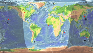
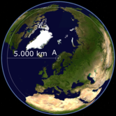
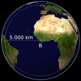
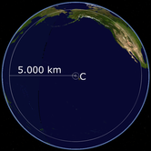
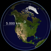
The system was based on 8 OMEGA broadcasting stations that were set up around the world. The transmitters had a long range of up to 10,000 nautical miles (18,500 km). With an earth's circumference of approx. 40,000 km, this corresponds to almost half the earth's circumference. A transmitter thus radiated almost up to its antipode and was thus receivable almost over the entire globe. Because of the long range, the distance between two stations could be 5,000 to 6,000 nautical miles (9,300 km to 11,100 km), which corresponds to approximately a quarter of the circumference of the earth.
| station | number | Location | Coordinates |
| A. | 1 | Aldra , Norway | 66 ° 25 'N; 013 ° 08'E |
| B. | 2 | Monrovia , Liberia | 06 ° 18 '20.0 "N; 10 ° 39' 43.9" W. |
| C. | 3 | Haiku , Hawaii , USA | 21 ° 24 'N; 157 ° 50 'W. |
| D. | 4th | La Moure , North Dakota , USA | 46 ° 21 '57.5 "N; 98 ° 20' 08.9" W. |
| E. | 5 | Reunion | 20 ° 58 '26.8 "S; 55 ° 17' 23.6" E |
| F. | 6th | Golfo Nuevo , Argentina | 43 ° 03 '12.5 "S; 65 ° 11' 27.5" W. |
| G | 7th | at Woodside , Victoria , Australia | 38 ° 28 '52.5 "S; 146 ° 56' 07.3" E |
| H | 8th | Tsushima , Japan | 34 ° 36 '53.5 "N; 129 ° 27' 13.0" E |
The system was built by the United States Navy and completed in 1968. Since 1971 it has been operated by the United States Coast Guard . In addition to two stations in the USA , from which the Omega system was initiated and maintained ( North Dakota and Hawaii ), six other stations were operated in allied or friendly countries ( Argentina , Australia , Réunion - belonging to France, Japan , Liberia and Norway ).
There was also an OMEGA station in Trinidad , which was shut down in 1980. The antenna systems built for the OMEGA stations were very large. Some had a self-radiating transmission mast over 400 meters high that carried a screen antenna . Other stations used a rope stretched over a fjord (Norway) or valley (Hawaii, Trinidad) as a transmitting antenna .
A detailed description of the transmitting stations follows below .
technology
OMEGA is one of the methods of hyperbola navigation . The system worked with longitudinal waves ( very low frequency , abbreviation VLF) in the range of 10 to 14 kHz (on 12 fixed frequencies - see below ), which enabled worldwide reception with the few stations.
OMEGA was designed as a navigation aid for long-range bombers , but also served submarines for position determination. The latter allowed the extreme wavelengths, since such radio waves also penetrate into salt water. Navigation with the Omega navigation method was possible up to a water depth of 15 m.
An accuracy of 2–4 nautical miles (NM - nautical mile) and later of 1 nautical mile was achieved. However, the disadvantage of the procedure was that - just like Decca - it required continuous measurement, so you could not determine your position just by switching on the system.
The American strategic nuclear submarines needed their exact position for the launch and the exact flight path calculation of their ballistic ICBMs equipped with nuclear warheads. The Ships Inertial Navigation System (SINS) - a closed dead reckoning system - served the submarines as the basic navigation system . The increasing position error had to be corrected daily with the help of a long-range navigation system (OMEGA).
The USA and Great Britain have assured the Australian government, among other things, that their nuclear submarines do not have OMEGA receivers installed in order to allay concerns in Australia that the Australian OMEGA broadcaster could in the event of a nuclear conflict between the USA and the SU could become the target of a strategic nuclear strike by the Soviet Union, which could thereby switch off the OMEGA navigation system for the American submarines.
functionality
The OMEGA navigation system broadcast from 8 stations worldwide with a frequency of 10 to 14 kHz . This is VLF (Very Low Frequency; long wave ), which is defined as a frequency range below 30 kHz. These electromagnetic waves spread around the entire globe because they are reflected at the lower limit of the ionosphere and from the earth (Fig. 1) (see space wave ).
Day-night border
The propagation of the longitudinal waves is very stable and therefore easy to predict. Problems there were, if both the sender and receiver were in different zones of daylight, so if the location of the transmitter, for example, lights day was while at the location of the recipient night was (Figure 2). Since the reflection properties of the ionosphere change at night (roughly simplified: the reflection occurs at a higher altitude and is stronger; during the day the lower limit of the ionosphere is 80 km high and at night it increases to 100 km), this constellation was useless for navigation, since the transitions at the day-night boundary were unstable and irregular. The OMEGA receiver therefore automatically switched to another transmitter so that the transmitter and receiver were once again in the day zone (or both in the night zone). The changed reflection height of the ionosphere at night leads to a different length of the path for the longest waves and thus to a disruptive and unpredictable phase shift (Fig. 3). For the sake of simplicity, only one single path of propagation is shown in the picture, although thousands of them exist side by side at the same time. However, the phase shift is decisive. Since the phase shift is used to calculate the distance, an unpredictable phase shift at the day-night boundary ( diurnal effect , diurnal phase shift ) makes the signal unusable.
Phase shift
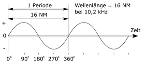
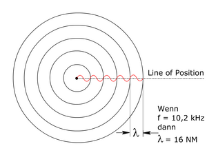
The longest waves used by the OMEGA navigation system have a wavelength of 16 NM (= 29.632 km) at a frequency of 10.2 kHz (Fig. 4). To better understand how it works, let's assume that an aircraft with the OMEGA receiver takes off just above the transmitter. The current location must be entered at the beginning of the flight. The phase shift across the station is zero. After another 16 NM flight away from the station, the phase shift is zero again. In the meantime, there is a gradual phase shift (Fig. 5), which is converted into distance units (NM) and displayed by the receiving device.
Location determination
Line of Position
The OMEGA receiver must remain switched on during the entire flight so that it can count how often a phase shift and a period (16 NM) occur. It can only give the exact distance from the OMEGA station (the position on a circular line around the transmitter), but not the direction. However, precise directional information is easily available for navigation using an additional compass.
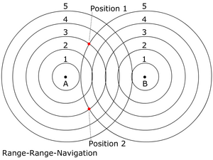
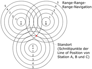
When evaluating two OMEGA transmitters, there are two possible locations. These can be differentiated with the help of a rough orientation on the compass. Because of the peculiarity of the OMEGA navigation process, the location with the help of two transmitters is ambiguous. With other navigation methods, two transmitters each assume a straight line and there is already a clear intersection. However, the OMEGA navigation method involves two circles that originate from two transmitters. These two circles naturally intersect at two points. Since it is only known that the receiver is somewhere on these circular lines, the receiver can be at one of the two points.
A clear determination of the position is only obtained when evaluating 3 stations. The distance to 3 stations gives a single point of intersection. Only the addition of a third transmitter resolves the ambiguity that still exists when navigating with two transmitters.
Hyperbola navigation is not to be equated with range-range-range navigation. It represents an even more precise navigation mode. There are special navigation maps for this purpose.
Frequency table
The 8 worldwide transmitters (A, B, C… to H) transmit strictly synchronously according to a fixed sequence and duration (Figure 11: transmission table - English transmission format , German: transmission format ). A transmission cycle lasts 10 seconds. Each station transmits successively on the four common frequencies (engl. Common frequencies ) (10.2 kHz; 11.05 kHz 11.33 kHz and 13.6 kHz) and additionally on a station typical frequency that is reserved for this station ( Station frequency , underlined in red in Figure 11). During a transmission cycle of 10 seconds, the station transmits exactly twice with the station frequency, this transmission pulse being approximately twice as long as the transmission pulses on the general frequency. A transmission cycle consists, so to speak, of 8 "clocks", of which 4 clocks are sent on the general frequencies and four clocks on the station frequency . The transmission pulses on the station frequencies overlap each other by one cycle. The pauses between the “clocks” are exactly 0.2 s, while the length of the individual clocks within a transmission cycle varies slightly - according to a fixed sequence. When looking at the individual columns of the transmission table, it becomes clear that 4 transmitters each transmit on their individual station frequency, while the other four transmitters transmit on the common frequencies, with only simultaneous transmission on different common frequencies within a "pulse" otherwise signal interference would occur.
The information from the transmission table was stored in the OMEGA receivers so that the receiver could clearly assign each station when it received the signals.
The four general frequencies are:
| frequency | Wavelength in NM | Wavelength in km |
| 10.20 kHz | 15.87 NM | 29.39 km |
| 11.05 kHz | 14.65 NM | 27.13 km |
| 11.33 kHz | 14.29 NM | 26.46 km |
| 13.60 kHz | 11.90 NM | 22.04 km |
For rough localization, mixed frequencies (3.40 kHz and 1.13 kHz) were used, which resulted from the difference between two suitably selected common frequencies.
- The frequencies for 15.87 NM (10.20 kHz) and for 11.90 NM (13.60 kHz) result in a difference of 3.40 kHz (13.60 - 10.20 = 3.4). 3.4 kHz corresponds to a wavelength of 47.61 NM (88.17 km).
- The frequencies for 15.87 NM (10.20 kHz) and for 14.29 NM (11.33 kHz) result in a difference of 1.13 kHz (11.33 - 10.20 = 1.13). 1.13 kHz corresponds to a wavelength of 143.25 NM (265 km).
The interference band with an amplitude of 143 NM was especially used by fast-flying aircraft for navigation, as the OMEGA receiver only recalculates the position display every 10 seconds. The station frequencies were:
| station | frequency | .. | station | frequency | ... | common frequencies |
| A. | 12.1 kHz | E. | 12.3 kHz | 10.2 kHz | ||
| B. | 12.0 kHz | F. | 12.9 kHz | 11.05 kHz | ||
| C. | 11.8 kHz | G | 13.0 kHz | 11.33 kHz | ||
| D. | 13.1 kHz | H | 12.8 kHz | 13.6 kHz |
The transmission power of an OMEGA transmitter was 10 kW .
Civil use
For civil use of the Omega navigation, only the common frequencies 10.2 kHz; 13.6 kHz and 11.33 kHz are used.
Synchronization of the transmission signals
So that the stations could send the timing signal exactly, they were equipped with an atomic clock . These atomic clocks were synchronized when the system started.
VLF transmitter
In order to guarantee the reliability of the navigation even if the reception of the OMEGA signals was not so optimal, the receivers were also able to evaluate signals from 7 VLF stations ( very low frequency , long waves ) around the world . These stations belonged to the VLF transmitter network of the US Navy (English naval VHF communications network ). However, these signals could only be used to calculate the distance from the station and not for automatic position determination. Most of them are still in operation today.
| number | Location | Coordinates | frequency | Transmission power |
| 1 | Cutler Naval Station, Maine | 44 ° 39 'N; 067 ° 17'W | 17.8 kHz | 1026 kW |
| 2 | Marine station Ebino (Japan) | 32 ° 05 'N; 137 ° 01'E | 17.4 kHz | 48 kW |
| 3 | Jim Creek Naval Radio Station , Washington State | 48 ° 12 'N; 121 ° 55 'W. | 18.6 kHz | 124 kW |
| 4th | Naval Station Lualualei (Hawaii) | 21 ° 26 'N; 158 ° 09'W | 23.4 kHz | 588 kW |
| 5 | NSS Annapolis, Maryland | 38 ° 60 'N; 076 ° 27'W | 21.4 kHz | 588 kW |
| 6th | Harold E. Holt Naval Station (Exmouth, Australia) | 21 ° 49 'S; 114 ° 10 'E | 22.3 kHz | 989 kW |
| 7th | Rugby (Great Britain) | 52 ° 22 'N; 001 ° 11 'W. | 16.0 kHz | 40 kW |
The Omega had two primary navigation modes:
- Hyperbola navigation (the highest and most precise level of OMEGA navigation)
- Range-Range-Range-Navigation (any possible combination of OMEGA transmitters or VFL transmitters was sufficient for this)
and two secondary navigation modes
- Range-range navigation
- Dead Reckoning (Engl. Dead reckoning )
The receiver always tried to work in "hyperbola navigation" mode whenever possible. If the signal reception was poor or if only two OMEGA transmitters were usable, he switched to a lower mode. If a reliable signal was lost, it switched to “dead reckoning mode”. In airplanes, it coupled a probable course with the aid of the last known position, the compass heading, the airspeed ( True Airspeed ) and the elapsed time.
OMEGA receiver
The OMEGA receiver consists of three components:
- Control / Display Unit (CDU) - German: control display unit
- Receiver Processor Unit (RPU) - German: Receiver processing unit
- Antenna / Coupler Unit (ACU)
Shutdown
Since GPS satellite navigation made it possible to determine the position much more precisely, which was also available worldwide, the OMEGA transmitting stations were switched off on September 30, 1997 .
In Russia, a comparable radio navigation system called Alpha was set up, which is still in operation.
The advantages of OMEGA navigation over Inertial Navigation (INS) were the lower price and higher reliability. In 1985 the price of an OMEGA receiver (control unit, receiver processor and antenna unit) for an aircraft was around US $ 35,000 compared to US $ 150,000 for an INS system. In terms of reliability, the mean time between failures (the mean operating time between failures) was 4,000 hours for the OMEGA system and 2,000 hours for the INS system. The repair costs were also much lower for an OMEGA receiver than for an INS system. The Omega receiver also had less sensitive parts. The OMEGA receiver was also superior in terms of location accuracy, as it was able to determine the location precisely every 10 seconds, while the accuracy of the position information provided by the INS system decreased as the flight progressed. Today, the accuracy of the INS system is significantly increased by comparing it with VOR signals .
Disadvantages of the OMEGA navigation compared to the INS navigation is the complete dependence on signals from a ground station (OMEGA transmitter, VLF transmitter), which can be disrupted by the enemy, especially for what was originally mainly military use. In contrast, INS navigation works completely autonomously - without ground signals - and was therefore absolutely justified in the military sector.
Both methods also have the disadvantage that they - just like Decca - required a position specification before starting the trip, which had to be particularly precise with the INS method, and that these navigation methods were based on a continuous measurement. So you couldn't find your position by switching on the system once. The navigation process also became unusable in the event of a business interruption (e.g. power failure at the receiver).
Description of the individual broadcasting stations
| Surname | Coordinates | description | |
|---|---|---|---|
| (A) Bratland | 66 ° 25 ′ 13 ″ N , 13 ° 8 ′ 13 ″ E | The station was located near Bratland in Norway and used a 3500 meter long wire antenna as a transmitting antenna, which was stretched between the Norwegian mainland and the island of Aldra . Solid concrete blocks served as attachment points. The antenna of the OMEGA transmitter Bratland was dismantled in 2002. | |
| (B) Paynesville | 6 ° 18 ′ 20 ″ N , 10 ° 39 ′ 52 ″ W. | The station was located near Paynesville in Liberia (near Monrovia ). It was inaugurated in 1976 and used a 417 meter high guyed steel lattice mast as a transmitting antenna , which was the tallest structure in Africa . The station was handed over to the Liberian government after the OMEGA navigation system was switched off on November 30, 1997. The station's transmitter mast was blown up on May 12, 2011. | |
| (C) Hawaii | 21 ° 24 ′ 17 " N , 157 ° 50 ′ 18" W. | The station is located near Kaneohe on the island of Oahu , State of Hawaii . Approximately 9 miles northeast of Pearl Harbor . The antenna is stretched over the Haiku Valley near the east coast of the island. | |
| (D) La Moure | 46 ° 21 ′ 57 ″ N , 98 ° 20 ′ 8 ″ W. | The station is located near La Moure in North Dakota (in the extreme south-east corner) and uses a 365.25 meter high guyed transmitter mast as an antenna system. Since the shutdown of the OMEGA radio navigation system, the transmitter has been used to transmit messages to submerged submarines . | |
| (E) Chabrier | 20 ° 58 ′ 27 ″ S , 55 ° 17 ′ 24 ″ E |
The station was near Chabrier on Réunion , in the Indian Ocean . The transmitter, the construction of which began on May 1, 1973 and which went into operation in 1976, used a 428-meter-high guyed steel framework mast as the antenna mast , which was one of the tallest structures in the southern hemisphere. It was demolished on April 14, 1999. |
|
| (F) | 43 ° 3 ′ 13 ″ S , 65 ° 11 ′ 27 ″ W. | The station was near Trelew in Argentina . This transmitter, the construction of which lasted from 1973 to 1976, used a 366-meter-high, braced steel framework mast , insulated from the earth, as the transmitting antenna , which was the tallest construction in South America . After the OMEGA radio navigation system was switched off, the system became superfluous and the mast was blown up on June 23, 1998. | |
| (G) Woodside | 38 ° 28 '52.4 " S , 146 ° 56" 7.1 " E | The station was located in Woodside, Victoria State , Australia . The station was originally planned to be set up in New Zealand, but was relocated to Australia after New Zealand anti-war protests. The transmitter is a shield antenna that is carried by a 432 m high guyed steel mast ( pardune ). This mast is the tallest structure in the southern hemisphere, at least until the planned thermal power plant is built in Buronga near Mildura . After it was closed as an Omega transmitter, the station is now operated as a Woodside VLF transmitter to maintain communication with submarines on the 13 kHz frequency . | |
| (H) Shushi-Wan | 34 ° 36 '53 " N , 129 ° 27' 13" E | The transmitter was located on Shūshi Bay ( 舟 志 湾 , Shūshi-wan ) on the island of Tsushima in Japan . It started operations in April 1975. Construction of the station building was completed in March 1973, while construction of the 389-meter-high transmission tower, which was designed as a guyed tubular steel mast and which was the tallest structure in Japan, was not completed until November 1973. In 1998, the station's transmitter mast was dismantled with the help of a climbing crane . At the location of the former transmitter building there is now a playground, an approx. 8 meter high memorial was built from the base of the mast at the location of the former transmitter mast, and a piece of the construction is located next to the mast as a display object. | |
| Trinidad | 10 ° 41 '0.1 " N , 61 ° 38' 13.3" W. | The station was on Trinidad , on the northwest side of the island. The OMEGA station Trinidad was shut down in 1980 . The OMEGA transmitter Trinidad used, similar to the systems in Norway and Hawaii, a wire stretched across a valley as a transmitting antenna. The buildings of the facility are still there today. Their use is unknown. |
Cultural meaning
The masts of some Omega transmitters were the tallest structures in the country and sometimes even on the continent in which they were located. In La Moure, North Dakota, the Omega station was the namesake for a motel. In the German science fiction novella “Der Komet”, the defense against a comet strike takes place on the area of the Omega Paynesville station.
See also
Web links
- seefunknetz.de - Radio navigation: Omega
literature
- Aviation Fundamentals. Jeppesen Sanderson Training Products, Casper, WY 1974, ISBN 0-89100-293-6 .
- Stephen F. Appleyard, RS Linford, Peter Yarwood: Marine Electronic Navigation. Routledge & Kagan Paul, London 1988, ISBN 0-7102-1271-2 . at google books
- JH Stanbrough: Experimental VLF Relative Navigation on R / V ATLANTIS II, Cruise 15. Reference No. 66-61, Woods Hole Oceanographic Institution November 1966.
Individual evidence
- ↑ Omega Motel on yelp.com
- ↑ Harald Lutz: The comet. Books on Demand, Norderstedt 2012, ISBN 978-3-8482-2709-9 .
