Wire rope

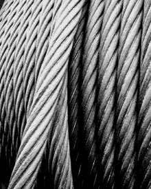
A wire rope (also: steel rope ) is a rope that consists of wires and not natural or synthetic fibers . The wires are made of metal , usually steel .
The term wire rope almost always referred to a so-called Twisted rope, in which the wires into strands and strands and these turned to the rope, so hit be. There are also braided ropes for special uses . The ropes of large suspension bridges , on the other hand, consist of many parallel, compressed wires. If the stranded ropes or wires are used to conduct electricity , they are called cables .
The twisting of the strands (see also the direction of lay ) is the prerequisite for a wire rope to be bent several times without breaking and, as is the case with rope pulleys and the sheaves of cable cars, for example . Because when the laid rope is bent, depending on the direction of bending, the twist is twisted or untwisted at this point, the entire rope becomes slightly shorter or longer and is subject to additional elastic tensile load or strain relief. When the rope is then forced straight (after the pulley of a cable car or when unwinding a pulley), the previous twist and change in length is canceled again. For both bending processes (bending crooked and bending straight again), bending work is necessary to overcome the internal friction between the strands (see also rope # lang's lay ropes ).
Thus, a rope not entzwirbelt under load by itself and stretches, several rope layers are in retaliation superimposed verzwirbelt, this results in the twist ssteifigkeit the rope that the back rotating force moment effected.
history
While ropes made of parallel wires are older and were already used by Marc Seguin for his suspension bridges, which were built from 1823, the laid wire rope was invented in 1834 by Oberbergrat Julius Albert in Clausthal . The chains used in the Upper Harz mining industry up to that point were damaged by the stress of rolling and unrolling and broke again and again, with sometimes devastating consequences. In order to prevent the total failure of the entire chain if only a single link was broken, Albert started experiments with a wire rope. It consisted of three strands of four wires made of wrought iron, each 3.5 mm in diameter. The rope was long lay (also called Albert beat) produced. The first practical tests were successfully carried out in February 1834 in the Caroline mine (Clausthal) .
Manufacturing
The wires are beaten on the stranding machines . A rotatable stranding basket carries a certain number of wire reels , from which the wires run through the stranding head (a disk with the corresponding number of holes) to the bearing and are wound helically around a core wire. The finished wire strand leaving the store is in turn wound onto a reel. The stranding comes about through the interaction of tension on the strand and simultaneous rotation of the stranding basket. The product produced in this way is referred to as a spiral rope , provided it is in this form, for. B. is used as a guy rope. On the other hand, strands are intended for further stranding.
In the next work step, several strands are twisted around a core by another stranding head to form the finished rope. The insert can consist of natural or synthetic fibers, a steel wire with or without a plastic cover or a plastic profile. Most of the stranded ropes used are twisted twice, but there are also ropes with several layers.
Braiding is based on the braiding formula .
Manufacturer
The wire rope industry in German-speaking countries is characterized by medium-sized companies. She coordinates herself in the wire rope association.
construction
The wires that make up wire ropes are normally made of carbon steel with a high carbon content of 0.4 to 0.9%. The very high strength of the wires is produced by cold drawing.
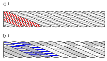
Because of the longer service life of the rope, lang's lay ropes are usually used, in which the wires of the wire layers do not cross. The ropes are called Lang lay ropes when the wire strands have the same impact direction as the strands themselves, and they are called lay ropes when the impact direction is opposite.
The simple shape of the rope in which the outer strands are visible is referred to as stranded rope or round stranded rope . They can be bare, galvanized or coated with different plastics in different colors. Ropes with the additional designation Seale have strands made of a steel core, a layer of thinner and a layer of thicker wire. Warrington-Seale refers to ropes with a wire core, two layers of thinner wire and one layer of thicker wire. Commercially available ropes have a diameter of 1.5 to 60 mm.
In the case of a compacted or compacted rope, the outer strands are passed through a drawing die and thereby flattened. This reduces the rope diameter and the smoothed rope runs more easily over pulleys and pulleys or through the sheath of a Bowden cable . With other stranded ropes, the strands are pressed onto an insert made of a plastic rod in such a way that the plastic completely fills the interior space between the strands, which stabilizes the strands and prevents them from touching.
Sealed ropes have an outer layer of profile wires that interlock so that the rope has a smooth surface and is largely protected from the ingress of moisture and dirt. Your outer wires cannot emerge from the rope bond if they break. Fully locked ropes have two such layers of profiled wire for better protection. They are mostly used as suspension ropes for cable cars. There are fully locked suspension ropes with a diameter of 90 mm, a minimum breaking force of 918 t and a weight of 48 kg per meter. Fully locked suspension ropes can also be equipped with integrated power and fiber optic cables .
Designations like 6 × 7 mean that the rope consists of 6 strands with 7 wires each. A 6 × 19 standard rope therefore has 6 strands, each consisting of 19 wires; an 8 × 36 WS has 8 strands with 36 wires each in the Warrington-Seale type. Letters like FC ( fiber core ) designate a fiber core , NFC a natural fiber core , SFC a synthetic fiber core and WC a steel core .
According to their construction (structure), the wire ropes are divided into classes according to DIN EN 12385. It also defines the rope sizes.
Limiting factors for the tensile strength or the length of a rope are not only the size of the stranding machine, but often also the total weight of the cable reel with the finished rope and the transport options to the place of use.
use


Wire ropes are used in different sizes and types for a wide variety of purposes, starting with the thin and flexible pull rope for the gear shift on the bicycle , the less flexible and stronger Bowden cable for the brakes and the rather stiff brackets for halogen lights, through ropes for operating medical examination devices that Ropes for controlling aircraft, especially black ropes for the lacing of theaters, over different ropes for elevators and the lifting of lock gates , for winches , excavators , cranes and cable cars to the ropes for cable-stayed bridges .
Simple stranded ropes are elastic, but stretch under load, become thinner and rotate when loads are freely suspended. However, ropes have to meet a wide variety of requirements. Through special construction and manufacturing methods, certain ropes are therefore particularly elastic and flexible, so that they can run over small rollers, and have favorable fatigue properties. Others emphasize low wear. Still others are resistant to high temperatures or are non-magnetic or particularly resistant to corrosion. Elevator ropes should have as constant a diameter as possible in order not to slip in the drive pulleys. Ropes for tensioning masts and similar holding ropes should not be extensible, so they are sometimes pre-stretched in the factory. Cable car suspension ropes should bend little under the rollers and be smooth and low-vibration on the outside for smooth running. Sling ropes should carry heavy loads, but should not break or twist at the edges of the load.
The four main types of rope are:
- Running ropes (stranded ropes) are stressed by tensile forces and swelling bending when running over sheaves.
- Standing ropes (mostly spiral ropes) are stressed by tensile forces - usually only slightly swelling.
- Support ropes (locked ropes) are loaded by tensile forces and, via support rollers, by transverse forces. The ropes do not take on the curvature of the support rollers because of the rope flexural strength.
- Sling ropes (stranded ropes) are stressed by tensile forces, but above all by bending during the mostly sharp deflection of the load.
equipment
In order to use ropes as a rope route , a rope binding is installed. There are extensive variants, such as ferrules to prevent the end of the rope from undoing, thimbles to reinforce a rope eye, turnbuckles , turnbuckles and so on. After all, only experienced specialists can use the special tendon anchors in prestressed concrete construction and the anchoring of the supporting cables of cable cars.
If two rope ends are connected to one another, for example because the rope is being used as a rope ring, the longitudinal rope connection is used.
Rope breaking force
The breaking force of wire ropes is determined by the diameter ( d ), the fill factor ( f ), the stranding factor ( k ) and the strength ( R m ) of the steel. The diameter ( d ) is the largest outer diameter of the rope (edge measurement). The fill factor determines the proportion of the steel cross-section in the total cross-section. The stranding factor depends on the design; Ropes always have a strength that is around 5 to 15% lower than the sum of the strength of the individual wires.
The minimum breaking force (MBK), i.e. the minimum force that the rope must achieve in the tensile test , is then calculated using the following formula:
For the widely used parallel lay ropes with steel core and the strength R m = 1770 N / mm 2 , for example, the minimum breaking force according to DIN-EN 12385 is:
Rating
Running ropes, which are used in a variety of ways, are considered. For applications in which people or property could be damaged if the ropes break, there are standards for dimensioning the rope drives. Above all, these standards specify the ratio of the minimum rope breaking force to the rope tensile force and the ratio of sheave and rope diameters. A generally applicable design method for rope drives, which is also often used in addition to the standards, calculates the five design limits:
- Number of work cycles (rope service life) until the rope is discarded or until the rope breaks. The number of work cycles must meet the requirements of the user.
- Donandt force (yield point of the rope wires depending on the bending diameter ratio D / d). Strict limit. The rope tensile force S at the nominal load must be smaller than the Donandt force SD1 (1% limit).
- Force break (ratio of minimum rope breaking force to impact force). The ratio of the minimum rope breaking force / rope tensile force Fmin / S = 2.5 ..... 12 depending on the type of rope drive, partly determined in standards.
- Discard wire break number (recognizability of rope discard maturity). For hoists where a load drop is to be prevented by inspection, the number of discarded wire breaks on a reference length of 30 times the rope diameter should be at least BA30 = 8.
- optimal rope diameter (economy). With a given rope tensile force and a given sheave diameter, the maximum rope service life is achieved with the optimum rope diameter. The rope diameter should be as large or slightly smaller than the optimal rope diameter, as the rope service life decreases again above the optimal rope diameter.
The calculation of these limits is relatively complex. A computer program Seilleb1.xls , which can be found at and can be used free of charge, calculates these limits.
Before using this method, the effective rope tensile force, the type and number of bends that the most heavily stressed piece of rope experiences per work cycle, and the approximate length of this piece of rope must be determined.
safety
The wire ropes are stressed by increasing tension, by wear, by corrosion and in rare cases by the effects of force. With a few exceptions, their service life is therefore finite. The safe use of wire ropes depends on the fact that they are discarded in good time before a dangerous situation occurs. The most important discard criterion is the number of broken wires on the reference lengths. The reference length of, for example, 30 times the rope diameter is used because, due to the stranding, the wires fully carry along after a few turns away from their breakage. It is a major advantage of wire ropes over other traction devices that some of the wires can be broken before safety is impaired. Because of the better visibility, the security increases with the size of the number of discarded wire breaks.
When the ropes are used to transport people, the usual visual and tactile rope inspection is not sufficient. In elevators, load-bearing ropes and safety gear are used in parallel to prevent falls. In the case of cable cars and shaft hoisting systems, the ropes are continuously checked using magnetic processes, which can also be used to detect internal wire breaks.
Parallel wire ropes

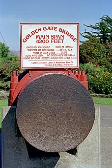
Parallel wire ropes are mainly used as suspension ropes for suspension bridges . They are so big that in the past they could only be produced directly on the bridge itself using the so-called air - jet spinning process. An auxiliary rope was pulled over the pylons in such a way that it describes the same curve as the planned suspension rope. A very large number of individual wires were pulled one after the other over the bridge by a wheel running back and forth on the auxiliary rope. The suspension cables of the Golden Gate Bridge were made this way. Each rope consists of 27,572 individual wires. The wires lying parallel to one another and not twisted or laid were each fastened in such a way that all wires bear the same load. Finally, the wires were sheathed and clamped together with rope clamps.
Prefabricated parallel wire ropes have also been used since the 1960s, which are also referred to as PPWS for P refabricated P arallel W ire S trand. This was only possible after investigating how these ropes could be wound onto cable drums without causing permanent deformation. Typically 37, 61, 91 or 127 wires are joined together to form a hexagonal cross-section. A cable drum with a parallel rope can weigh up to 85 tons today. The technique was first introduced on a large scale in Japan. Examples of bridges with suspension cables made of prefabricated parallel ropes are the Jiangyin Bridge in China or the Kammon Bridge and the Akashi-Kaikyō Bridge in Japan .
See also
Phrase
As a balancing act is known other than the original acrobatic demonstration of acrobats on a tightrope figuratively a dangerous or difficult undertaking, in which the practitioner the balance reserve needs.
People with "nerves like wire ropes" are considered to be extremely psychologically resilient.
literature
- Peter Sedivy: Lecture materials for cable car construction at the Institute for Infrastructure, Intelligent Transport Systems division, University of Innsbruck, summer semester 2012 (PDF; 85.5 kB)
- Roland Verreet : Wire ropes in court - compilation of typical and less typical wire rope damage in text and images (PDF; 4.5 MB), accessed on July 21, 2012
Web links
- Of wires and strands - wire rope production in 1834
- Colloquium - 175 years of the invention of the wire rope
- Breaking load calculator for wire ropes
Individual evidence
- ^ Lueger: Lexicon of all technology - rope manufacture
- ↑ Fatzer Archive, December 2008: Production of 90 mm ropes
- ↑ K. Feyrer: Wire ropes, dimensioning, operation, safety. Springer-Verlag Berlin, Heidelberg 2000, 2nd edition ISBN 3-540-67829-8
- ↑ Wire rope Excel programs from the University of Stuttgart
- ↑ Checking the rope - magnetic induction test ( page no longer available , search in web archives ) Info: The link was automatically marked as defective. Please check the link according to the instructions and then remove this notice. in the lecture materials for cable car construction at the Institute for Railway Engineering a. Transport Economics of the Graz University of Technology, WS 2011, page 22 f. (PDF file), accessed July 21, 2012
- ↑ Information board in the photo of the exhibited piece of rope
- ^ Cable Supported Bridges: Concept and Design . 3. Edition. John Wiley & Sons, 2011, ISBN 978-1-119-95187-2 , pp. 88-89 (English). Online PDF; 4.7 MB ( memento from October 26, 2012 in the Internet Archive )


