
Pantograph

A current collector is a device on vehicles for transmitting electrical energy from a current-carrying conductor mounted along the roadway to the electrically operated systems of the vehicle. There are three types of energy absorption:
- permanent supply of the electric drive while driving: electrically driven rail vehicles , trolley buses , trolley line boats , catenary ferries and Autoscooter
- Permanent supply of secondary consumers such as lighting and heating while driving: funicular railways , certain trams - sidecars if there is no train busbar , for example with the Bielefeld type MB4
- additional supply to a weakly laid out train busbar, for example in the heating car of the Rhaetian Railway
- selective stationary supply while standing: dining car when changing locomotives while staying at the station, battery buses , gyro buses
Designs
Contact shuttle
The first electrical overhead lines were two-pole slotted pipe contact lines . This system was presented for the first time at the International Electricity Exhibition in Paris in 1881 and required special contact boats that were guided through tubes that were slit on the underside. Contact boats were first used in planned operation from 1883 on the Mödling – Hinterbrühl local railway and from 1884 on the Frankfurt-Offenbacher Trambahn-Gesellschaft (FOTG).
Siemens slotted pipeline, International Electricity Exhibition 1881 in Paris

Contact trolley at one of the two poles of the FOTG's Siemens slotted pipeline
Switch of a Siemens slotted pipeline in the Frankfurt Transport Museum


Contact trolley
An alternative to the contact shuttle were small four-wheeled contact cars with rollers that ran on the two contact wires like a trolley and were pulled by a connecting line behind the motor vehicle. This principle, developed by Werner Siemens , was first used in the electric vehicle presented in 1882, and later it was also used in rail vehicles.
The English term trolley for such vehicles - later provided with fixed rods instead of cable connections - is derived from these contact trolleys . This applies in particular to trolleybuses, which are therefore called trolleybuses in large parts of the world. However, the contact cars tended to derail, and driving on junctions ( switches ) in the overhead lines was problematic. The contact cars were therefore handed over to each other at train crossings .

1882: Kontaktwagen at the Elektromote, the world's first trolleybus

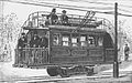
Mine railway locomotive in France, with two roller trolleys as pantographs, 1897
.jpg)

Pantographs
Pantograph with contact roller (roller pantograph)


Only the changeover to pantographs pressed against the contact wire from below , dispensing with the contact car, made the power supply operationally reliable. These pole or roller pantographs, also called trolley pantographs in Switzerland, are among the oldest designs. The American engineer Frank J. Sprague first used it in 1889 on the tram in Richmond, Virginia . The Thomson-Houston company improved the system and made it known in Europe. In Germany, the system was first used at the Northwest German Trade and Industry Exhibition in Bremen in 1890 .
Today, roller pantographs usually consist of a long rod that is mounted at an angle on the vehicle roof and is pushed upwards by a spring. At its upper end there is a (brass) roller with a groove along the circumference, which rolls along the contact wire from below and makes the electrical contact. Another contact is the graphite bearing , which connects to the rod. The relatively small diameter of the current collector roller leads to high speeds in fast moving vehicles.
Compared to the later developed pantographs, the roller pantographs have some serious disadvantages:
- The pantograph can slip off the catenary (so-called rod derailment ) and damage the catenary or other lines.
- If there are no turning loops available at the end points , it must be switched manually when changing direction . To do this, the staff has to pull off the bar with a rope, walk in a wide arc around the vehicle and put it back on the other side. Therefore, long four-axle bidirectional cars often had two roller pantographs, because the staff had to stand directly under the catenary to thread the contact roller
- The overhead line construction is more complex than with hoop pantographs, since the contact line must be installed without kinks. It must follow the curved track precisely, which requires additional suspensions and thus additional catenary masts and rosettes with cross wires. In addition, the contact wire must be welded endlessly.
- Special catenary switches (so-called " air switches ") must be installed in the case of branches . An alternative is to move the bar manually, but this means additional operating stops and thus increases the travel time. In some cases, contact wires were used twice on single-track lines in order to be able to dispense with air switches at least for evasion .
- The catenary is more prone to icing up during operation because, unlike in ironing, it is not scratched free.
- Manual wiring or rewiring is more difficult in the dark.
From 1890, roller pantographs were widely used worldwide, especially in trams. However, the technical inadequacies gradually led to the elimination of the roller pantograph. The last tram operation in Germany with pantographs was the Hamburg tram ; it was shut down in 1978. If a company cannot modernize its wagon fleet for decades, as is the case in large parts of America, then wagons with roller pantographs are often in use there.
The last European tram operators with roller pantographs are the Lisbon tram , which, however, only operates two out of five lines with this system due to the restricted clearance profile and the proximity to the windows of residential buildings in the narrow streets, the Porto tram , the Sintra tram , the Tramvia Blau in Barcelona , the Manx Electric Railway and the Blackpool tram , on which some of the vehicles run with pantographs. They can still be found more often in the United States , for example on the F Market & Wharves Line in San Francisco and the Ashmont – Mattapan High Speed Line in Boston . Other non-European systems are the Alexandria tram and a company in Calcutta .
Dickinson system (1893)

A further development of the Sprague system from 1889 was the Dickinson system, which was introduced four years later and which was particularly popular in Great Britain. On February 21, 1893, also in the United States, inventor Alfred Dickinson patented a pantograph with a joint at the base and at the tip of the rod, i.e. the roller is rotatably mounted on the car roof and on the head of the rod can also be rotated around a vertical axis.
With this principle, also known as the Dickinson roll, the contact wire no longer had to follow the track geometry exactly because the pantograph bar allowed a lateral deviation of up to three and a half meters. In particular, in tight bends or counter-bends in close succession without an intermediate straight, significantly fewer anchoring points were necessary. In addition, catenary masts erected on one side on the sidewalk could also be used in the middle of the street . Thus, the tram companies did not have to rely on the consent of the homeowners to allow them to attach overhead line rosettes for the cross wires or masts did not have to be erected on both sides of the street. In addition, the overhead line masts could be equipped with shorter, more inconspicuous arms. The Dickinson system was particularly advantageous for double-decker trams with an open upper deck, the so-called deck seat cars . Due to the laterally offset contact wire, the passengers sitting above did not run the risk of coming into contact with the overhead line when standing up. In Germany, the first railcar of the Dresden tram , built in 1893, was equipped with a Dickinson pantograph.
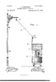
Dickinson patent specification, part 1
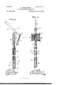
Dickinson patent, part 2

Dickinson patent, part 3

Dickinson patent, part 4


Pole current collector with sliding shoe
A further development of the current collector with contact roller is the current collector with sliding shoe, also called contact shoe. Instead of the roller, an exchangeable carbon grinding piece is used here. Above all, this enables a larger contact surface compared to the roller. The Stansstad – Stans tram, which opened in 1893, used such contact strips. At the beginning of the 20th century, this principle was further developed by the engineer Max Schiemann especially for trolleybuses by making the pantograph heads rotatable. This system was used for the first time on the Bielathal motor railway, which was operated from 1901, with electrical overhead lines . It is still the standard for trolleybuses today. Contact shoes with rotatable bearings allow the vehicles greater tolerances with regard to the lateral deviation, so that they can also drive a few meters next to the overhead line. This makes it easier to guide the contact wire, particularly near buildings and in S-curves. On the other hand, sanding shoes also require the installation of air switches.
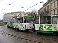
The system is still occasionally used in trams today, for example on the Daugavpils tram , the Philadelphia tram , the Riga tram and the Toronto tram . The Austrian Pöstlingbergbahn was converted from roller to grinding shoe operation after the First World War and operated in this form until 2008.

Tramcar in Toronto with pantographs

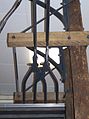
Toronto: Detail of the sanding pad

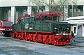
Railcar of the Pöstlingbergbahn
Tram train in Riga

Head of a trolleybus pantograph


U-shaped pantograph
Lyra pantograph


The first hoop pantograph was invented by the German engineer Walter Reichel in 1889 and presented at the world exhibition in Paris that same year . It consists of a metal bracket mounted on the vehicle roof that is pressed against the catenary by springs. This metal bracket is sometimes curved and is reminiscent of a lyre , which is why the terms lyre pantograph or lyre bracket have become commonplace. In the upper area of the metal bracket, a one to two meter wide contact strip is installed across the direction of travel , which makes contact with the contact wire. It consists of carbon, in rare cases of copper. Contact strips simplify the implementation of the overhead contact line compared to the roller pantograph, as overhead line switches can be dispensed with and kinks in the contact wire path are tolerated. When changing the direction of travel, Lyra pantographs also have to be folded or turned. When pulled by the trolley, the customer slides better and there is less risk of damage if it should get caught.
Lyra pantographs were used between 1890 and 1920 in the railways and trams. The low contact pressure led to the formation of arcs and thus caused radio interference (see arc transmitter ). They were therefore largely supplanted by the pantographs. They were able to prove their efficiency in the high-speed tests in 1903 on the Marienfelde – Zossen – Jüterbog military railway near Berlin, where they were used at speeds of up to 210 km / h. A prerequisite for the use of hoop pantographs was a previous modification of the contact line. To prevent notches in the contact strip, the contact wire must be laid in a zigzag. In arcs, a polygon replaces the previous laying in the track axis with many support points. When operating with scissor-type pantographs or single-arm pantographs, the conditions are comparable; vehicles with lyre, scissor-type and single-arm pantographs can be used together without any problems.
Pantograph
The first pantographs with two-dimensional rods that were used in a tunnel on the Baltimore & Ohio Railroad in connection with a lateral overhead line since 1895 were roller pantographs. The classic three-dimensional scissors or "pantograph" pantographs combine the principle of the sliding frame mounted across the direction of travel ("Lyra" and others) with a scissor mechanism that presses the contact strip vertically from below against the catenary and aligns it upwards. The scissor mechanism is similar to that of a pantograph , which is why scissor pantographs are also called that. Unlike lyre and roller pantographs, scissor pantographs can be used for both directions of travel. Due to the shorter lever arms, they are less prone to vibrations and thus guarantee more continuous contact between the contact wire and pantograph even at high speeds.
In Germany in 1897 the Nürnberger Elektrizitäts-Aktiengesellschaft, formerly Schuckert & Co. developed a bow-type pantograph for mine railways, the pantograph rod of which even carried a so-called pantograph head with two contact pieces. In the area of application at that time, it was only a matter of suitability for both directions, not yet suitability for speed. The San Francisco, Oakland, and San Jose Railway (SFOSJR , later Key-System ) began operations in 1903 with the first bracket pantographs in public transport . They were built in the company's workshop. The designer was John Q. Brown, an employee of the railway company.
Originally, and especially in the case of trams for a long time, and in some cases still today, pantographs are pressed against the contact wire by springs, pulled off with a line and locked in this position. Pneumatic lowering drives were first introduced in long-distance rail vehicles. Existing springs only compensate for the mass of the frame; if the compressed air supply fails, the pantograph lowers automatically. The German pre-war locomotives had hand air pumps in a driver's cab for the first upgrade when compressed air was not yet available.
There are basically three ways in which the contact strips (brackets) are mounted on the scissor linkage:
- There is only one contact piece that sits directly on the tip of the “scissors” and is held by the latter so that its curved ends point straight down.
- The grinding piece has the shape of a lyre bow with very short arms, is held vertically by springs in the rest position and folds backwards while driving.
- The scissor linkage presses a so-called rocker or pallet with two or more contact strips onto the contact wire.
For a long time, pantographs with only one contact strip predominated. It was not until 1960 that the range became generally accepted.
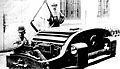
Roller pantograph, US mining locomotive 1895

Roller pantograph on the Baltimore and Ohio Railroad in 1895

Scissor pantograph with pallet in the Saar mining industry, 1897

Bow pantograph with simple contact strip, Kleve 1961

Scissor pantograph with pallet in Tokyo public transport
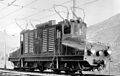
Industrial locomotive with pantographs for central and side contact lines


Single-arm pantograph

With the increase in travel speed, the reliability of the pantographs reached their limits. This led to the development of the half-scissor and single-arm pantograph. The reduction from at least nine to only three scissor braces enabled a massive reduction in the air resistance of the pantograph and thus a significant improvement in contact wire contact. The mass could also be reduced. The smaller space requirement and the complete foldability are also advantageous when multi-system vehicles have to be equipped with several pantographs for different overhead line systems. Despite their asymmetrical design, single-arm pantographs are usually designed in such a way that they behave in the same way in the knee gait (joint to the front) as in the gauntlet (joint to the rear).
After the record runs in 1955 by the SNCF CC 7107 and BB 9004 (331 km / h each) with extreme arcing on the traditional pantographs, the Faiveley company near Paris developed the Einholm pantograph in the same year and the SNCF first developed it on the record locomotive BB 9004 tested. The test drives took place on a newly electrified 25 kV line in northeast France in the winter of 1956/57. Since the contact line was not yet live, the test locomotive had to be pushed by a high-speed steam locomotive in order to test the pantograph behavior.

The first AM11 single-arm pantographs used in series were made by Schneider / Jeumont MTE on the French SNCF BB 16000 alternating current locomotives, which were put into service at the beginning of 1958, and on the newly commissioned BB 16500 "Danseuses" from Alsthom, Belfort, from July 1958 accepted. From 1958 onwards, they were built on all of the new French electric locomotives of the SNCF, albeit with a slightly different design in more recent times. In 1959 they came with a built in French license Russian locomotive and at the Bo'Bo' locomotives of the British series 81 for use (even if only one pantograph per machine). At the Deutsche Bundesbahn , single-arm pantographs were used as standard for the first time in the series 181 and 184 and in larger numbers from the beginning of the 1970s on the railcars of the 420 series and the locomotives of the 111 series, and for the ÖBB with the 1042 series . The Deutsche Reichsbahn first used them in series on the 243 series (now the 143 series). In Switzerland, the single-arm pantographs were tested on two Bernina railcars (37 and 38) on the Rhaetian Railway in 1962 and on all new vehicles from 1964, on the SBB Re 4/4 "on a trial basis from 1967 (11107-09) and systematically from 1969 (from 11156 ), in Norway they were only introduced from 1985. In Italy, too, the pantograph remained the standard for a long time, as was the case with the first series of high-speed power cars ETR 500 .
While single-arm pantographs were initially pressed against the contact wire like scissor pantographs with tension springs and lowered with a pneumatic lowering drive, air bellows are predominantly used today, which allow the contact pressure to be adjusted depending on the requirements of the overhead contact line system (important for multi-system vehicles) and enable an automatic lowering bracket device, which in the A break in the contact strip responds and prevents major damage to the overhead line. In the case of trams, the principle of putting on with spring force and pulling off with the pantograph line remained common for a long time. Today, the pantographs on wagons without compressed air supply are equipped with motor drives.

In the case of high-speed pantographs in particular, the contact strips are additionally individually cushioned in order to be able to follow unevenness in the contact wire path less sluggishly and to minimize arcing . A pantograph was developed for the Shinkansen , the drive of which is mounted on a plate with a streamlined panel, which makes it quieter in operation.
In the mid-1970s, after several damage to overhead lines caused by the pantographs in high-speed operation, these were replaced by single-arm pantographs in the 103 series . Since not enough single-arm pantographs were available at the beginning, some of them were replaced with the 111 series. Since the mid-2000s, scissor pantographs have increasingly been replaced by single-arm pantographs on Deutsche Bahn locomotives during revisions, for example in the 140 , 151 and 155 series .
Today, the single-arm pantograph is the general standard and has also established itself in vehicles that rarely drive over 50 km / h in normal use.
Pantographs with sliding arm

A combination of the above-mentioned main forms are pantographs that were subsequently equipped with a grinding bracket arranged transversely to the contact line. It was developed in order to be able to use historical trams under modern overhead contact line systems. An example of this is the Pilsen tram .
Multipole pantographs
Multi-pole pantographs are also available for three-phase and two-pole direct current systems with a neutral point.

In 1902 Kandó Kálmán developed three-phase locomotive of the Italian RA 361–363 series , a pantograph that was only electrically split for the two-pole catenary

Three-phase current railcar from Siemens in 1903, grinding rings arranged one above the other for the three-pole catenary

AEG 1903 three-phase motor car, one behind the other arranged grinding bows for the three-pole catenary

Jungfrau Railway, double pantographs for the two-pole three-phase catenary
Electric locomotive Le Drac 1903, double lyre pantograph for the two-pole direct current contact line


The ship lift on the Krasnoyarsk Reservoir uses three pantographs.
The battery buses that have been operating in Vienna since the end of 2012 use a two-pole single-arm pantograph during the charging process.
Busbar pantograph

In the case of U- and S-Bahn trains with busbars arranged to the side of the track, there are pantograph brackets of a simpler design that slide along, sideways or under the busbar. The Wuppertal suspension railway also uses such a system.
System variants in Europe
As a result of various technical and structural framework conditions, various types of contact line have developed on the continental European rail network, which require different pallet widths, contact strip materials and pantograph construction methods. Therefore, multi-system vehicles for international traffic must be equipped with different pantographs. The designs differ in the width of the pantograph, the type of contact strip material used and the cushioning of the pallet. The lateral deflection of the contact wire and the clearance profile available in the pantograph area have a limiting effect.
In the course of harmonization for cross-border traffic on the TEN corridors, a uniform geometry was defined, which is known as the Euro seesaw . It was defined in TSI rolling stock (2008/232 / EC) Section 4.2.8.3.7.2.
| Areas of application | Power system | Pallet width | Contact strip material | |
|---|---|---|---|---|
| Denmark, Germany, Norway, Austria, Sweden, Slovakia, Czech Republic, Romania, Bulgaria | AC voltage | 15 kV / 25 kV | 1950 mm | graphite |
| France, Luxembourg, Switzerland | AC voltage | 15 kV / 25 kV | 1450 mm | graphite |
| Hungary (until catenary adjustment) | AC voltage | 25 kV | 2060 mm (1950 mm also works in Hungary after the adjustment) | graphite |
| Croatia, Bosnia-Herzegovina, Serbia, Montenegro, Macedonia, Greece, Turkey (partially) | AC voltage | 25 kV | 1650 mm | graphite |
| Belgium, France, Luxembourg (until 2018), the Netherlands, Slovakia, the Czech Republic | DC voltage | 1.5 kV / 3 kV | 1950 mm | Metallized graphite |
| Italy, Slovenia | DC voltage | 3 kV | 1450 mm | copper |
| Poland | DC voltage | 3 kV | 1950 mm | Metallized graphite |
| Russia | AC and DC voltage | 25 kV, 3 kV | 2250 mm | Graphite (alternating current), copper (direct current) |
| Euro seesaw | AC and DC voltage | 1600 mm | graphite | |
Functionality and monitoring of pantographs with contact strips

While driving, the contact strip is in constant dragging contact with the contact wire, apart from brief interruptions due to unevenness in the underside of the contact wire or vehicle bumps. The current flows from the contact wire through the contact strip and the metal support or support structure, which is insulated from the roof, to the roof line, which forwards the current to the main switch or into the vehicle interior.
Both the contact strip and the contact wire constantly wear out due to friction. Contact wire and contact strip must therefore be replaced regularly when they are in the appropriate condition. Since the contact wire can only be changed with considerable effort, a softer material is selected for the contact strips, so that the wear of the consumer is higher and the contact wire is protected. In order to make the wear of the contact strips evenly and to avoid cutting into the contact wire, the contact wire is stretched in a zigzag over the track in contact lines for contact wire pantographs.
If the contact strip breaks while driving, the contact line can be torn down by the pantograph's support structure that is pushing upwards. Modern pantographs therefore have contact strip monitoring. A brass tube is inserted lengthways into the contact strips and connected to a compressed air supply. If the tube is rubbed or breaks, the current collector is lowered by the pressure drop.
Most mainline locomotives have two pantographs. Usually, the one at the rear in the direction of travel is placed in order to prevent parts from falling onto the roof equipment and the still intact pantograph in the event of damage, and to minimize the risk of flashovers due to contamination of the insulators of the roof equipment due to conductive contact strip abrasion. At higher speeds, the rear pantograph is also usually located in an aerodynamically more homogeneous layer of air with fewer air turbulences. In the case of double traction or leader , the foremost and rearmost pantographs of the locomotive combination are used to reduce contact wire vibrations and lift. Vibrations and air turbulence can cause the pantograph to briefly jump off the contact wire. Loss of contact - even very brief - is far more significant in modern vehicles because of the many electronic components that depend on a continuous power supply for correct function than in older vehicles, which can cope better with this. The need for an uninterruptible power supply combined with the increasing speeds led to new designs, the suitability of which is checked primarily with the ICE S and other railway service vehicles . The rule of using the pantograph at the rear in the direction of travel is deviated from because of the possibility of sparks, even if inflammable goods or cars are transported directly behind the locomotive or a control car is employed. Multi-system vehicles, which often only have one pantograph per electricity system, represent a special case; there is then no option here.
In the case of trams, the aerodynamic effects are not particularly significant due to the lower speeds. The front pantograph is often used there; this is partly coupled with the direction of travel. The main reason for this was that in the past, the switches in many tram networks were switched via contact line contacts and the overhead current. The position of the front pantograph is easier to assess from the driver's cab.
If you only want to use one pantograph, it should be equipped with at least two contact strips (or contact strips), as direct contact is lost with the smallest bump. In the early days of electrically operated railways, the pantographs had only one contact strip, which is why both pantographs are always placed on historical photos. This is still the case today with icy contact wires. However, shortened protective routes and system separation points may not be driven with two raised pantographs. The pantographs connected by the roof line would bridge the neutral section and trigger a short circuit or earth fault. If it is necessary to drive in such a section with two pantographs, then ironing must be carried out in front of the protective section or system separation point.
Contact strip / contact strip
Theoretically, any electrically conductive material can be used as a contact strip / contact strip . Nevertheless, two types of contact strips are mainly used in German-speaking countries today, those made of graphite and aluminum alloys . In addition, the are in a 3-kV direct voltage network FS also copper -Schleifleisten in use. Copper contact strips are very heavy, so that the pantograph reacts more slowly; therefore a high contact pressure on the contact line is necessary. To cope with this, the overhead contact line must be made more stable, so that it in turn becomes heavier and tends to sag. However, copper is a very good conductor with better material properties than aluminum and carbon and there is also no corrosion of the copper contact lines. While only copper contact wires are practically used today, those made from galvanized steel wire were also used in the past. With these, a carbon contact strip was the worse choice.
Electrochemically, there are always disadvantages when different materials are used as contact strips on the same contact line. Either graphite or aluminum contact strips must be used for the copper contact lines. Mixed operation is to be avoided, as the use of graphite contact strips on a contact line that is used with aluminum contact strips destroys the conductive oxidation layer, while a contact line bare with graphite contact strips attacks aluminum contact strips. In a figurative sense, this also applies to copper contact strips.
Model railways
Model railways with overhead lines use prototypical designs as pantographs, but not in the form of pantographs, as the construction of a suitable overhead line would be too complex. Model railway locomotives, which get their electricity from a central conductor within the running rails, use contact strips that are pressed against them with springs. In some cases, especially in the case of large nominal sizes, there are contact pads in the two-rail, two-wire system that rest on the rail heads. There are similar constructions for electric children's railways at public festivals.
literature

- K. Eifert: Electric vehicle pantograph . In: Berliner Verkehrs-Aktiengesellschaft (ed.): The journey . Issues 14 and 15, 1931.
- Helmut Petrovitsch: Half-scissors or Einholm? In: Modelleisenbahner , Volume 68, December 2019, pp. 46–49.
Web links
Individual evidence
- ^ A b c Norbert Kuschinski: Exhibition trams . In: Verkehrsgeschichtliche Blätter . Volume 3, 1988, pp. 60-68 .
- ^ Paul F. Schneeberger: Verkehrsbetriebe der Stadt Luzern, 100 years of trams, buses and trolley buses. Minirex, Luzern 1999, ISBN 3-907014-12-X , p. 226.
- ^ A b Johannes Zacharias: Electric trams , 1903, page 87
- ↑ Patent US491988 A by Alfred Dickinson from February 21, 1893
- ↑ Lexicon of the local transport interest group in Magdeburg on ignah.de, accessed on January 24, 2016 ( Memento of the original from January 24, 2016 in the Internet Archive ) Info: The archive link was inserted automatically and has not yet been checked. Please check the original and archive link according to the instructions and then remove this notice.
- ^ Railways to Engelberg. ISBN 3-907014-10-3 , p. 28.
- ^ City of Berkeley - Historic Survey: Transportation; Fig. 84 possibly already shows the second generation of vehicles (PDF; 1.6 MB)
- ^ Peter Willen: Locomotives of Switzerland 2nd narrow-gauge traction vehicles. Orell Füssli Verlag, Zurich 1972, pp. 167–169.
- ^ Peter Willen: Locomotives of Switzerland, standard gauge traction vehicles. Orell Füssli Verlag, Zurich 1975, third supplemented and revised edition, ISBN 3-280-00800-X , pp. 15 and 16.
- ↑ Data sheet for the Schunk WBL pantograph family
- ↑ Data of the Stemmann DSA pantograph family
- ↑ Bärbel Jossunek, Vasco P. Kolmorgen, Alexander Wolf: route brochure New Erfurt - Leipzig / Halle. (PDF) (No longer available online.) In: DB Netz; Infrastructure & technology; Customer information. Railway concept, August 13, 2015, p. 12 , archived from the original on August 16, 2015 ; accessed on August 15, 2015 . Info: The archive link was inserted automatically and has not yet been checked. Please check the original and archive link according to the instructions and then remove this notice.
- ↑ Technical specification for the interoperability of the “rolling stock” subsystem of the trans-European high-speed rail system
- ↑ Janicki: Vehicle technology. Volume 2, 1st edition, ISBN 3-9801093-8-0 , p. 82.