
SBB Ae 3/6 II
| SBB Ae 3/6 II | |
|---|---|
 Ae 3/6 II 10439
|
|
| Numbering: | 10401-10460 |
| Number: | 60 |
| Manufacturer: | SLM Winterthur, machine factory Oerlikon |
| Year of construction (s): | 1921-1926 |
| Retirement: | 1965-1977 |
| Axis formula : | 2'C1 ' |
| Length over buffers: | 14,090 mm |
| Height: | 4,500 mm |
| Service mass: | 98.5 t (10401-10420) 96.7 t (10421-10460) |
| Friction mass: | 55.3 t (10401-10420) 56.3 t (10421-10460) |
| Top speed: | 100 km / h |
| Hourly output : | 1,475 kW (2,000 hp) at 65 km / h |
| Continuous output : | 1'225 kW (1'665 PS) at 75 km / h |
| Driving wheel diameter: | 1,610 mm |
| Impeller diameter: | 950 mm |
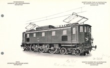
The SBB Ae 3/6 II is a standard gauge , single- frame , universal locomotive with single-axle drive for alternating current of 15,000 volts 16 2 ⁄ 3 Hertz. It was ordered in 1921 and 1926 for the then newly electrified railway lines of the Swiss Federal Railways (SBB) in the lowlands and put into operation in a brown color. Many of the 60 machines delivered were in use until the 1970s, most recently in green.
The locomotives were commissioned on the structural basis of the test locomotives Be 3/5 . The Ae 3/6 II was the last series-built locomotive with a rod drive in Switzerland. The rod drive was still used, however, in newly built electric station tractors, which did not reach too high a speed, as well as in newly built shunting locomotives, because for a long time locomotives with mechanically coupled driving wheels had advantages in terms of skidding compared to shunting locomotives with individually driven driving wheels, due to the lack of an efficient anti-skid system.
prehistory
The serious coal shortage towards the end of the First World War led to a decision in 1918 to electrify the SBB in order to become independent of the foreign energy supplies in the form of coal . This decision was supported by the fact that Switzerland was considered a pioneering country in electrical engineering by the fact that at this time hundreds of kilometers of mostly meter-gauge road, overland, mountain and mountain railways were already being driven electrically, probably primarily with direct current, but the basis for comprehensive rail line electrification by alternating current of 15,000 volts 16 2 ⁄ 3 Hertz was provided by the electrically operated Lötschberg mountain line ; the electrification of the Gotthard mountain route was nearing completion.
At the beginning of the first electrification phase in 1920, the SBB had drafts for a flatland universal locomotive drawn up. Only a few points were required, including: three drive axles , an output of 2000 hp, a top speed of 90 km / h and a maximum axle load of 20 t. The three Swiss electrical companies Brown, Boveri & Cie (BBC), Maschinenfabrik Oerlikon (MFO) and Société Anonyme des Ateliers de Sécheron (SAAS) otherwise had a largely free hand. The following drafts were submitted and then also procured: BBC: Ae 3/6 I , MFO: Ae 3/6 II and SAAS: Ae 3/5 .
Specification book
The SBB required the industry to meet the following specifications :
- Top speed 90 km / h
- Transport of 480 t trailer load on 2 ‰ incline at 90 km / h
- three return journeys Zurich - St. Gallen (85 km) with 480 t trailer load in 10 hours
- three round trips Villeneuve - Brig (117 km) with 480 t trailer load in 11½ hours with a 15-minute stop at the terminus
- Starting a trailer load of 480 t on a gradient of 10 ‰ and accelerating to 55 km / h in a maximum of four minutes
Installation
The Ae 3/6 II 10401 was already put into operation on January 19, 1923 and subsequently extensively tested immediately. The remaining locomotives were commissioned between spring 1924 and summer 1926.
technology
The mechanical part
The Ae 3/6 II is based on the design of the Fb 3/5 11201 test locomotive . However, since only one transformer was installed instead of two and there was no space in the middle of the locomotive due to the large drive motors , the transformer had to be installed offset to the outside. This led to the 2'C1 ' wheel arrangement.
landing gear
The running gear consisted of three drive axles fixed in the locomotive frame . The middle drive axis had a side play of 2 × 15 mm. A running axle was arranged at one end of the locomotive . This was designed as a Bissel axis and had a side clearance of 2 × 83 mm (10401-10420) or 2 × 70 mm (10421-10460). On the other side was the two-axle running axle bogie . As a whole, this had a side clearance of 2 × 80 mm.
Traction transmission
The traction and impact forces were transferred from the drive axles to the locomotive frame. From there, the external forces were transferred to the draw hooks and buffers .
drive
The two overhead traction motors were firmly screwed into the locomotive frame. The torque was transmitted from the sprung drive motor pinions to two countershafts , which were also firmly mounted in the locomotive frame. The two countershafts jointly carried a slot drive rod . This directly drove the central drive axis via a vertically movable bearing. Short coupling rods were mounted on the triangular slot drive rod (triangle rod ) , which drove the outer drive axles.
Locomotive body
The locomotive box of the vehicles was screwed onto the frame. There were two blinds on the side walls, from number 10421 there were three. Also from number 10421, small sun visors were placed over the two large driver's cab windows . The traction motors were separated from the rest of the engine room by partitions. They were accessible through doors in the right side aisle. The roof structure over the motors included ohmic traction motor shunts and the switching inductor. The lightning protection coil on locomotive 10401 was also arranged in this structure. The cooling air for the traction motors was sucked in from the engine room with a fan. After cooling the coated equipment, she left the locomotive through the side blinds of the roof structure.
Braking system
The automatic, one-way Westinghouse brake and the regulating brake acted on each of the three drive wheels on both sides and on the wheels of the bogie on one side. The bitch salmon was unbraked.
Sand spreading device
The compressed air- powered sand spreading device could be kept simple, as the three drive axles were connected by coupling rods and therefore, unlike the single-axle drive , a single axle could not be thrown on its own. Therefore only the leading drive axle was sanded.
The electrical part
Main circuit
On the roof of the locomotive were the two pantographs that were pneumatically operated by the driver's cabs . From these the catenary current was fed to the main oil switch. This was located at numbers 10401-10413 in a rectangular housing and was operated electro-pneumatically. The numbers 10414-10460 installed an electric motor-driven main oil switch in a round housing, which was installed as a normal device in all SBB locomotives from this point on. In the case of locomotives 10401-10413, the main switch could also be switched on by hand with a socket wrench on the switch itself. With the remaining locomotives, this was done from the driver's cabs. For the emergency triggering of the main switch, there was a lever in every driver's cab within close reach of the locomotive driver.
The electricity came from the main switch to the transformer. This was located above the first drive axle and the bogie in the locomotive body. On the low-voltage side, it had two winding halves, each with eight taps for powering the traction motors. The voltages on these taps were both numbers 10401-10420 between 134 V and 536 V, with the remaining locomotives between 99 V and 545 V. In addition, one winding half of all locomotives had taps for 220 V for the auxiliary services. This winding half also had an additional winding for train heating with 800 V and 1,000 V (originally also for 600 V with the numbers 10401-10420).
The power of the transformer of numbers 10401-10420 turned out to be a little too weak for the thermally generously dimensioned traction motors. For this reason, a more powerful, but at the same time lighter, transformer was installed in the following locomotives. Therefore, the locomotives 10421-10460 with a service weight of 96.7 t were also somewhat lighter than the previous models with 98.5 t.
Another disadvantage of the transformers in the first 20 machines was the rough gradation of the first speed steps. The start-up was therefore very rough and sometimes difficult or even impossible.

There were two step switches for regulating the voltage . These were arranged lengthways in front of the transformer and accessible from driver's cab I. The step switches were built as cam-controlled lever mechanisms with spark extinguishing switches and switch-over choke coils. They were driven by an electric motor and could switch a total of 17 speed levels . In the event of a malfunction, the steps could be switched from both driver's cabs using an attachable handwheel.
Incidentally, the tap changer construction was the same as that used for the Ce 6/8 II . The same circuit was later used again for the Ce 6/8 III .
The traction motors weighed around 10 t and had a diameter of 1,800 mm. They were the largest engines ever built for SBB. They were always connected in series . If a motor failed, the cutting knife could be removed from the associated reversing switch and inserted between the motors. The same procedure was followed if a step switch or reversing switch failed. It could then, if possible, continue at half power.
The reversing switch was operated mechanically from the driver's cab. In contrast to this, number 10401 had electropneumatic reversing switches, which were retained even after the recuperation brake was removed.
Auxiliaries
The following described, 220 V-operated auxiliaries were located on the locomotive:
- a compressor behind the driver's cab II (10401-10435: rotary , 10436-10460: piston compressor )
- a fan for cooling the traction motors, assembled directly with them
- an oil pump with oil cooler behind the driver's cab II
- Converter group for battery charging via the oil pump
- Cab heating and oil heating plate
Electric brake
The Ae 3/6 II 10401 had a recuperation brake . It was a loner until it was shut down and the equipment was largely normalized in 1928.
Multiple controls
The Ae 3/6 II never had multiple controls .
Major renovations
The Ae 3/6 II were spared major modifications. The main changes were:
- The top speed was increased from 90 km / h to 100 km / h in 1929
- Trials with rod bearings lubricated with grease instead of oil in different variants from 1957 onwards with the numbers 10406, 10407, 10415 and 10439. The variant on the 10406 with so-called floating bushes made of Tokat bronze with a steel core was the best and was installed from 1960 onwards.
- After experiments with split brake pads and brake slack adjusters from 1961 on the 10449 locomotive, this arrangement was still installed in most locomotives.
Operational use
After the early commissioning on January 19, 1923, intensive test drives were carried out with the Ae 3/6 II 10401. It soon became apparent that the transformer was a bit weak. Otherwise there were no problems with the fulfillment of the specification.
Delivery of the series began in April 1924. This extended until June 1926. The depot allocation ex factory was as shown in the following table:
| Numbers | Depots |
|---|---|
| 10401-10404 | Zurich |
| 10405-10413 | Olten |
| 10414-10438 | Basel |
| 10439-10449 | Olten |
| 10450-10460 | Lucerne |
The number of delivered locomotives exceeded the demand. The numbers 10433-10438 delivered in the summer of 1925 were declared "surplus" in SBB District II. With the advancement of electrification in the 1920s, however, the need was definitely there and the locomotives subsequently changed their depot allocation and operations frequently.
On June 1, 1924, there were three services for the newly delivered locomotives in the Olten depot and five in the Basel depot . These services covered the management of through freight trains. In addition, they were used to handle the entire Basel - Lucerne train service with an average daily performance of 330 km.
In June 1926 the following allocation existed:
| Numbers | Depots |
|---|---|
| 10401-10406 | Winterthur |
| 10407 | Zurich |
| 10408-10410 | Olten |
| 10411-10413 | Zurich |
| 10414-10438 | Basel |
| 10439-10449 | Olten |
| 10450-10460 | Lucerne |
In 1927 the first Ae 4/7 were delivered. These took over the most difficult services in Basel and District III. The use of the Ae 3/6 II therefore shifted more to Eastern Switzerland (District III). In the summer of 1928 the following distribution resulted:
| Numbers | Depots |
|---|---|
| 10401-10405 | St. Gallen |
| 10406-10409 | Rorschach |
| 10410-10412 | Zurich |
| 10413-10416 | Romanshorn |
| 10417-10424 | Olten |
| 10425-10434 | Basel |
| 10435 | Bellinzona |
| 10436-10446 | Olten |
| 10447 | Bellinzona |
| 10448-10449 | Olten |
| 10450-10460 | Lucerne |
What is interesting is the division of the locomotives into one-man and two-man management positions:
| depot | Number of locomotives |
Services unanimously |
Two-man services |
Average daily performance |
|---|---|---|---|---|
| Basel | 10 | 6th | 1 | 286 km |
| Olten | 21st | 10 | 10 | 243 km |
| Lucerne | 11 | - | 7th | 250 km |
| Bellinzona | 2 | 2 | - | 274 km |
| Zurich | 3 | with Ae 3/6 I. |
||
| St. Gallen | 5 | - | 5 | 216 km |
| Rorschach | 4th | - | 4th | 241 km |
| Romanshorn | 4th | - | 4th | 246 km |
The one-man tours of the Basel depot mainly involved guiding freight and passenger trains to Olten , Lucerne and Zurich.
The two-man tours included three express trains and one passenger train between Basel and Lucerne with a daily output of 382 km.
The one-man tours led from Olten to Biel , Bern , Basel and Zurich. They included all types of trains, including a Zurich - Bern express train. The two-man tours included services to Biel, Thun , Basel, Lucerne and Zurich. They made all kinds of trains.
Three locomotives manned by two men were assigned to the Goldau secondary depot . They took care of the local freight traffic in Freiamt . They also ran a pair of trains from Aarau to Olten, Goldau to Zug and Goldau to Erstfeld .
The allocation of two Ae 3/6 II to the Bellinzona depot was interesting . One tour included the passenger trains 553 Bellinzona - Lucerne, 552 Chiasso and 2573 Bellinzona. The daily mileage was 450 km. The second locomotive led the pair of freight trains 5543/5548 from Chiasso to Lugano . In Lugano she had to take on extensive shunting work. Previously, this service was carried out by a reserve steam locomotive until 1926. From 1929 an SBB De 6/6 took over this service. The other performance was taken over by a Be 4/6 in May 1929 .
The Ae 3/6 II of the depot Zurich were in exchange for the Ae 3/6 I used. The other operational plans of District III were as follows:
St. Gallen:
Passenger and freight trains to Zurich and Rorschach .
Rorschach:
Express, passenger and freight trains to Zurich and Romanshorn . This also included the express trains 26/25 to Zurich and back. In addition, the express train 10 was run from St. Gallen to Zurich, where it was taken over by an Ae 3/6 II from the Zurich depot further west.
Romanshorn:
Express, passenger and freight trains to Zurich.
During the 1930s, the locomotives became more and more concentrated. Locomotives 10451-10460 were permanently moved from Depot Luzern to District III. The numbers 10451-10455 came to Rapperswil SG . The numbers 10456-10458 were moved to Romanshorn. 10459–10460 finally landed in Zurich.
In the summer of 1939 the deposit allocation was listed as follows:
| Numbers | Depots |
|---|---|
| 10401-10413 | Olten |
| 10414-10429 | Lucerne |
| 10430-10438 | Basel |
| 10439-10447 | Olten |
| 10448-10460 | Zurich |
The locomotives at the Olten depot were entrusted with the management of passenger and freight trains to Biel, Bern, Basel, Lucerne and Zurich in eleven roles. From the Olten secondary depot in Aarau , five round trips were made, mainly by passenger trains, to Olten, Goldau and Zurich. The Ae 3/6 II from the Lucerne depot ran passenger trains to Olten, Zurich and Goldau as well as express trains via Langnau to Bern in nine scheduled services . From 1937 to 1945 there was a two-day umlaut in Ticino . This began on the first day with the management of a passenger train from Lucerne to Chiasso. This was followed by the management of various passenger and freight trains to Bellinzona and Lugano. On the second day the return trip to Lucerne took place with a Chiasso - Lucerne passenger train.
The Basel locomotives carried passenger and freight trains to Lucerne, Bern over the Bözberg and also to Delsberg .
The Zurich machines were represented all over District III.
The snapshot in the summer of 1949 showed the following deposit allocation:
| Numbers | Depots |
|---|---|
| 10401-10421 | Olten |
| 10422-10429 | Lucerne |
| 10430-10439 | Basel |
| 10440-10447 | Olten |
| 10448-10460 | Zurich |
Interesting was a service of the Lucerne depot from 1947 to 1949. This included a pre-tensioning service on the express trains 56 Lucerne - Lugano and 65 Lugano - Lucerne. An Ae 4/6 was used as a train locomotive . The trailer load had already been exceeded according to the train formation plan, which required a leader on the 26 ‰. In 1950 there was still a preload service before Zug 64 Luzern - Göschenen and a return line as a preload before Zug 64 to Lucerne.
In the summer of 1957 there was a very serious shortage of electric locomotives. Especially the Ae 3/6 II of the district II achieved comparatively large daily mileages:
- Basel: ten services with passenger and freight trains to Delémont (Delsberg), Biel, Lucerne and Zurich. In addition, all types of trains were run from Basel SBB station to Basel Badischer Bahnhof . The Ae 3/6 II often had to help out in front of express trains due to a lack of locomotives even with SBB Ae 4/7 services. The average daily output of the Basel locomotives was 308 km.
- Olten: The locomotives assigned to the Olten depot carried passenger and freight trains to Basel, Biel, Bern and Zurich. The average daily mileage was 335 km.
The locomotives used from the Aarau secondary depot were divided into 14 services to guide the same types of trains to Biel, Bern, Zurich, Goldau, Zug and Herzogenbuchsee - Lyss . They achieved an average daily mileage of 324 km. - Lucerne: Five services were scheduled here, which ran to Zurich, Olten, Bern and Göschenen by passenger and freight trains. The average daily mileage here was 348 km.
In 1960 the distribution of the still complete inventory was as follows:
| Numbers | Depots |
|---|---|
| 10401-10443 | Olten |
| 10444-10460 | Winterthur |
The EXPO 64 year ( Swiss National Exhibition ) was the last with a complete inventory of Ae 3/6 II . They were divided as follows:
- Olten: 34 services with passenger and freight trains as well as express train 411 Goldau - Lucerne. The routes via Brugg to Zurich, Basel - Delémont - Moutier , Biel, Bern, Lucerne - Zug - Zurich, Winterthur - Wil , Koblenz and Schaffhausen were served . The average daily mileage was 355 km.
- Winterthur: 15 passenger and freight train services throughout District III as well as to Basel and Wohlen . The average daily output was much lower at 280 km.
The Ae 3/6 II 10415 was retired as the first locomotive of the type in January 1965 . On August 8, 1961, she fell down the embankment in Lengnau after a flank run with an Ae 4/7 . It could be set up with the existing aids, but not lifted back onto the track and was therefore completely dismantled into individual parts. These ended up in the main workshop in Yverdon , where they were straightened and reassembled. As a result, it was reinstated, but remained a problem child because it was particularly prone to overheating . When it was brought back to Yverdon for repairs at the end of 1964, it was demolished.
In August 1965 the 10436 followed (after a collision in Gisikon ), in 1966 the 10403, 10405 and 10416 were broken off. But even at the beginning of the seventies, the locomotives even ran express trains or extra trains in the case of double guides. In the summer of 1973 there were 14 services at the Olten depot with an average daily output of 253 km. With the management of passenger and freight trains, they still came to Zurich, Basel, Lucerne, Erstfeld , Biel and Bern.
From 1974, the Ae 3/6 were II of the depot Olten more and more by Ae 3/6 I replaced. The number 10453 was the last to be scrapped in January 1977. Some locomotives served as preheating systems for passenger coaches for a long time . There are no accidents with a catastrophic character in the Ae 3/6 II .
The 10452 locomotive has largely been returned to its original condition (including brown paint) and will thus be preserved for posterity as an operational locomotive. Because it was first decided in favor of the preservation of 10439, but this was in poor condition, 10452 was renumbered to 10439 ". In order to avoid downtime damage, it is sent out on the route with light tasks from time to time. Otherwise it is available for special trips to disposal.
Conclusion
The locomotive was robust in its construction, but with the rod drive it was no longer up to date, which was due to the fact that the MFO, unlike its competitors BBC and SAAS , did not have a tried and tested single-axle drive.
Thanks to its high-lying traction motors, the locomotive was much less sensitive than its sisters Ae 3/6 I , Ae 3/5 and Ae 3/6 III in winter operation . However, the maintenance effort was much higher, especially because of the rod drive.
See also
literature
- Hans Schneeberger: The electric and diesel traction vehicles of the SBB, Volume I: years of construction 1904–1955; Minirex AG, Lucerne; 1995; ISBN 3-907014-07-3 .
- Claude Jeanmaire: The electric and diesel locomotives of the Swiss railways, the locomotives of the Swiss Federal Railways (SBB).
Web links
- The Railfaneurope.net Picture Gallery
- Pictures of the Ae 3/6 II in the digital railway photo archive
Individual evidence
- ↑ Where is the plain? , a radio broadcast by Swiss Radio and Television (SRF) from Sunday, March 4, 2012, 9:15 a.m., accessed on December 12, 2019
- ↑ History, Unter Strom - how Switzerland was electrified, by Stefan Boss , an article from July 8, 2018 in Swissinfo.ch (SWI), accessed on December 12, 2019