propeller
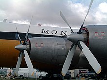
A propeller (from Latin propellere , `` to drive forward '') is a machine element of a prime mover with blades that are usually arranged radially (star-shaped) around a shaft .
In technical terms, one often speaks of propellers and no longer of ship's propellers, even for ships . In aircraft , the propeller is sometimes referred to as a propeller ; In the case of helicopters , the load-bearing effect dominates the propulsion, which is called the rotor . In the case of wind turbines , which work according to the same principle, simply withdrawing power from the air flow instead of generating it for propulsion or buoyancy , one also speaks of a repeller.
Classification according to machine type
Propellers are elements of a turbomachine that take up mechanical work and transfer it to the surrounding medium in the form of flow energy; these are counted among the working machines . The Austrian imperial and royal naval forest manager Josef Ressel , who received a patent on February 11, 1827 in Austria, is considered to be the inventor of the first functional propeller for boat propulsion .
Working principle and applications
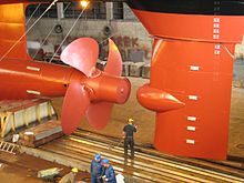

The blades are shaped and aligned in such a way that when the rotor rotates, the surrounding medium, for example air or water , flows around them at an angle or asymmetrically. The wings experience dynamic lift , the axial component of which is taken up by the rotor bearing and referred to as thrust , and causes an opposing flow of the medium, the rotor jet . If it is not important to generate pressure, as is the case with air-cushion boats , but rather thrust is required, then the efficiency increases with increasing rotor area, since the rotor radiation absorbs less kinetic energy with the same momentum when its mass increases.
The tangential component of the lift, together with the flow resistance, causes a torque which the drive has to deliver via the shaft and which sets the rotor jet in rotation. While in pipe flows the energy loss associated with the rotation of the flow can be greatly reduced by means of the rotor upstream and / or downstream guide vanes, in free flows a high-speed number (reciprocal of the so-called degree of progress ) of well above one is chosen if possible .
The flow towards the blade profile results from the superimposition of the flow speed of the medium through the rotor surface and the self-movement of the blades, which increases from the inside to the outside (the former may be the sum of the travel speed through the medium and the accelerated movement of the medium in the rotor jet). The direction of this effective flow changes from the inside to the outside. By twisting the blades, a largely constant effective angle of attack is achieved over the entire blade length.
In order to be able to use higher speeds in liquids without the occurrence of destructive cavitation , flat blades with low lift coefficients are used, which completely fill the rotor surface or even overlap one another, while very slender blades are used to accelerate the relatively thin air (with also high lift coefficients) sufficient.
Towards the outside, the flow velocity increases almost linearly, the possible lift per profile depth thus almost quadratic, the necessary lift (with the swept annulus area) only linearly, which is why the necessary profile depth decreases in inverse proportion to the radius.
Pusher propeller
If the propeller is mounted so that it does not "pulling" (traction propeller; English tractor configuration ), but "pushes" he is as a pusher propeller (. English pusher configuration ), respectively. In aircraft, this propeller arrangement enables the pilot , among other things , to sit in front of the propeller in the direction of flight. This arrangement was used on the French Farman MF11 in 1913 and was then adopted in the First World War, for example by the British Airco DH1 and the single-seat Airco DH2 , in order to be able to fire a forward-pointing machine gun without damaging the propeller. The Saab 21 fighter aircraft was flown until around 1951.
There are also combinations of pull and push propellers possible (English. Push-and-pull propellers ), such. B. the Dornier Do 335 , the Cessna Skymaster and the bomber Piaggio P.50 . A concept of a combination of jet engines and pusher propellers was used in the Convair B-36 .
An example of the pusher propeller apart from the typical propeller drive is the rail zeppelin designed by Franz Kruckenberg , which was driven by a two-blade or four-blade propeller depending on the route profile .
Pusher propellers are often used on weight- controlled ultralight aircraft .
Since the pusher propeller is usually behind the wing, one promises a theoretical advantage over the pull propeller, which is usually in front of the wing. The pulling propeller in front of the wing sets the air flow in a spiral movement and thus disrupts the ideal aerodynamic flow around the wings, while the pusher propeller cannot, at least in theory, negatively influence the flow around the wings. However, with the pusher propeller, the aircraft parts in front of the propeller (fuselage, wings, engine nacelles) interfere with its ideal flow and effectiveness; therefore, configurations with a pusher propeller tend to be less efficient than comparable configurations with a draft propeller. They also tend to be louder because the propeller blades run through the wake of, for example, the wing, which in each case generates a rapid change in the pressure distribution on the blade, which is in the audible range at the usual rotational frequencies.
As an advantage, a pusher propeller offers improved longitudinal stability, i.e. i.e. when the aircraft nods up, it generates a nodding moment and vice versa (both as a function of the pitch angle and the pitch rate). The same applies to the yaw angle and rate. A draft propeller has the opposite effect. Therefore, pusher propellers are mostly used in aircraft that are configured unusually in terms of longitudinal stability, such as canard configurations ("duck aircraft").
Characteristic values
- The degree of progress (also known as the advance ratio)
- defines the ratio of the axial flow speed to the (reduced) propeller peripheral speed . It is the abscissa in the free travel diagram over which the following three functions are plotted.
- The dimensionless shear coefficient
- The dimensionless torque coefficient
- The free travel efficiency
where T is the propeller thrust, Q is the torque, D is the propeller diameter, n is the speed and the density of the medium. Strictly speaking, the free-travel efficiency only applies to "homogeneous inflow" (without the presence of a ship). As a function of the degree of progress, it shows a maximum that should be adhered to for particularly energy-saving drives. The arrangement of the propeller on the ship results in interactions that are referred to as the suction number, the wake number and the quality of the arrangement and which, together with the free travel efficiency of the propeller, determine the quality of the propulsion.
In contrast to aircraft turbines, aircraft propellers have a significantly higher efficiency of 80 to 90%, but only at speeds of up to around 700 km / h. Ship propellers can also achieve these values, but only if the thrust coefficients are sufficiently low, which seldom apply due to the limited draft and propeller size.
Geometric parameters
diameter
The diameter of a propeller is the diameter of the circle that its wing tips describe during rotation.
The choice of the diameter depends on the speed at which the propeller should turn, the available power and the desired speed. With the same performance, the diameter is usually larger for slower boats and smaller for faster boats. If all other variables remain the same, the diameter increases with increasing power, as well as with decreasing speeds (due to lower engine speeds and / or higher gear ratios) or with surface propellers.
In the case of rapidly rotating aircraft propellers, the material strength and rigidity of the blades and the speed of the blade tips are often a limiting factor in the diameter. If the blade tip speed exceeds the speed of sound, considerable noise and poor efficiency can be expected. Something similar happens when the blade tips start to vibrate due to the air turbulence generated by the propeller itself, combined with a lack of rigidity .
The possible diameter is also partially limited by structural conditions, e.g. B. the anti-ventilation plate in outboard engines or the ground clearance of aircraft.
pitch
The geometric gradient corresponds to the distance that a propeller would cover during one revolution in a solid material, comparable to a screw in wood. The corresponding geometric shape is a helical surface . Propeller surfaces on the pressure side actually largely correspond to this shape - except in the hub area.
A propeller labeled 13¾ × 21 is 13¾ inches (35 cm) in diameter and has a pitch of 21 inches (53 cm). Theoretically, this propeller would cover a distance of 53 cm in one revolution.
The slope is measured on the wing surface, usually the pressure side.
There are two types of slope, either constant or progressive. The constant slope remains the same from the front to the rear edge, i.e. it corresponds to a profile without curvature of the pressure-side surface. The progressive slope begins flat at the leading edge and slowly increases to the trailing edge. The average value of the pitch is given for such propellers. The progressive incline gives more thrust for medium and high performance.
The slope has a strong influence on speed and torque and thus on the choice of motor and gearbox. Small inclines are suitable for generating powerful thrust even at low speeds, while large inclines are suitable for achieving good levels of efficiency in low-resistance vehicles. A good compromise is often achieved with a pitch that matches the diameter.
Tilt
If you look at a propeller along a cutting line that goes through the center of the hub, the angle between the wing and the perpendicular to the hub gives the inclination of the wing.
If the wing is perpendicular to the propeller axis, the propeller is inclined at 0 °. The more the wing points backwards, the stronger the slope. With standard propellers, the pitch varies between −5 ° and 20 °. Series propellers of outboards and sterndrives usually have an inclination of about 15 °. High-performance propellers with a steeper pitch often have a progressive pitch that increases along the length of the wing and can reach 30 ° at the wing tip. The slope is either linear or progressive.
A greater inclination improves the behavior of the propeller in the event of cavitation and ventilation that occurs when a wing penetrates the surface of the water. The wings bundle the water that would otherwise be thrown away by centrifugal force better than those with a lower incline; the thrust is therefore stronger than with similar propellers with a lower pitch.
As a rule, aircraft propellers have no inclination.
Direction of rotation
There are right and left handed propellers. A right-hand propeller rotates clockwise when viewed from the rear.
Number of wings

A single-bladed propeller is, in principle, the most efficient, since here the flow on the rotating propeller blade is least disturbed by the turbulence of the leading blade. However, it needs a counterweight, loads the drive shaft asymmetrically and vibrates relatively heavily in boats, which is why this type of construction is rarely used.
An increasing number of sheets brings about the following qualitative changes:
- decreasing efficiency
- greater power that can be transmitted for a given diameter
- smaller required diameter and thus lower blade tip speed
- rising manufacturing costs
- increasing smoothness (important for boat propellers)
In particular, if the individual blades are exposed to different currents via the propeller circle, a higher number of blades has a favorable effect on the vibration behavior.
Double-bladed propellers are most common on piston-engine-powered aircraft, while three-bladed propellers are more common on boats. The turboprop and propfan engines of larger aircraft, on the other hand, have 3 to 7 or even more blades. Surface propellers, which alternate between air and water with every revolution, have even more blades.
Airplanes and submarines also have counter-rotating double propellers on a common (geometric) axis.
Slip
Slip is the difference between the theoretical and the actual forward movement of the propeller, caused by the angle of attack. For example, if a propeller with a pitch of 100 cm actually moves only 85 cm forward in one revolution, the slip is 15%.
The slip is calculated as the ratio of two lengths and is therefore a completely different quantity than the degree of efficiency, which expresses the efficiency of the energy conversion. The two sizes cannot be converted into one another. Example: With a vehicle moving away, the slip is initially 100% (as long as the vehicle is still stationary) and then decreases quickly because the vehicle accelerates and achieves more and more forward distance per revolution. The efficiency changes only insignificantly during this time, because the approaching vehicle is pushed with approximately even power. The efficiency of a propeller is highest at a certain speed (approximately normal cruising speed); the efficiency decreases at higher or lower speeds.
Skew
When skew (Engl. For wrong ) the wings reserve is called. It is defined as the angle between the chord that generates lift and its zero point at the center of the shaft of a propeller blade; d. In other words, on the propeller circular surface, the wing tip is offset by the skew above the hub. Modern ship propellers usually have a strong skew. In this way, strong pressure amplitudes can be reduced, as individual wing cuts provide lift to different rotation angle coordinates. Changes in the flow therefore do not hit the entire wing at the same time, but only different radial areas one after the other. Skew is therefore also a means of reducing propeller-induced pressure fluctuations (vibrations).
Physical effects that limit performance
Cavitation
High-speed ship propellers can lower the water pressure on the negative pressure side of the propeller to such an extent that bubbles occur which collapse again very quickly and thus cause mechanical damage ( cavitation corrosion ). This phenomenon can be reduced by reducing the propeller speed and using appropriately shaped low-cavitation propellers. Submarines can also circumvent this problem by increasing the diving depth, as this increases the static pressure. Cavitation damage can also occur on poorly shaped oars.
Cavitation is unavoidable at very high speeds, however, and so there are certain supercavitating propellers, the wing shape of which promotes full (= full-surface) cavitation in order to at least reduce the damage caused by partial cavitation.
Vortex formation
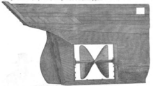
In addition, eddies form at the wing tips in both air and water . This is due to the Helmholtz vortex theorems. The individual wing can only generate dynamic lift if a vortex movement is superimposed on its flow around it, and according to Helmholtz a vortex cannot simply stop at the wing tip. The vortex filaments bend backwards at the wing tips and are twisted helically into one another. They represent part of the power that the propeller leaves useless in the medium. In general, the efficiency of a propeller improves if less twist remains in the water or in the air. In shipbuilding there have been and still are different approaches to untwisting the flow: an asymmetrical aft ship, the Grim's stator (a non-drive propeller rotating in the same direction as the active propeller) and, recently, rudders with differently positioned upper and lower halves ("twisted spade rudder ").
The Grim's idler wheel, which is freely rotating behind the propeller, is designed for a speed that is around 40 percent of the speed of the propeller. This means that the stator can be made larger than the propeller in front of it. The inner part of the stator located in the propeller jet is designed as a turbine in its profile design. This gives the stator its rotation. The outer part outside of the propeller jet receives profiles that are designed like a propeller. This creates an extra boost. The combination of “propeller plus stator” has a larger effective jet cross-section than the propeller alone. The subsequent arrangement of a guide wheel results in efficiency improvements of 3 to 15 percent. However, the problems caused by the entry of seawater into the sealing system, which led to numerous damage in the years after 1983, have not yet been solved.
These problems were investigated by shipbuilding research institutes with model tests and CFD calculations , but not solved. Therefore there are no longer any ships that use a guide wheel.
ventilation
Ventilation occurs when air from the surface of the water or exhaust gases from the exhaust is drawn into the propeller. This reduces the load on the propeller; the engine over-revs and the thrust decreases. Outboards and sterndrives have a plate above the propeller as part of the underwater housing. This anti-ventilation plate is usually incorrectly referred to as a cavitation plate. In reality it is supposed to prevent air from the surface from entering the negative pressure side of the propeller.
Executions
The number of blades of propellers is variable. It can consist of only one wing (e.g. single-blade rotor of the Bölkow Bo 102/103 ) and is in principle unlimited. For large container ships z. B. the number is currently limited to seven in terms of production technology. The decisive factor for the number of blades is the pressure difference in the media flow before and after the propeller. If the progress rate is particularly low, the difference becomes too great and the flow stops. This effect is reduced with a nozzle surrounding the propeller . Ships that have to provide much more thrust than would be required for their own propulsion in open water often carry jet propellers, especially tugs and icebreakers.
Extreme cases of propellers are the Archimedes' screw and turbine wheels .
While propeller blades are almost always arranged in a star shape (radial) around a shaft, the Voith-Schneider Propeller has retained a small market niche as a patented special solution . It gives watercraft a special maneuverability, as you can turn its thrust in all directions. It is a rotating disc in the bottom of the ship, from which the wings protrude downwards like a spade. A device that can be compared to the swash plate of a helicopter continuously changes the angle of attack of each wing depending on its current position.
A distinction is made between fixed propellers and controllable pitch propellers for ships as well as aircraft . Variable pitch propellers can change the pitch of the wings in order to re-adjust the most effective pitch for different loads (aircraft climbing, ship is towing something). Aircraft such as the ATR 42 can also maneuver backwards on the ground.
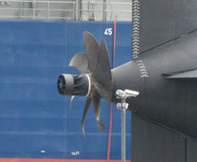
Sickle screw or sickle propeller are designs that use sickle-shaped curved blades instead of straight blades. These are quieter (especially important for submarines) and have a lower resistance close to the speed of sound. The weaker compression shocks also reduce material fatigue. Disadvantages are higher weight and higher price because of the complicated shape. Examples of sickle propellers are the A400M (aircraft) and the Akula class (submarine). The kinked propeller ends in helicopters (e.g. UH-60L ) represent a transitional form, which reduce the noise, as the propellers at the tips come into the range of supersonic speed.
Folding propellers , which are used in sailing yachts and gliders with auxiliary drives, are a specialty . When the engine is running, the centrifugal force rotates them, the blades hit a stop under thrust and act like a normal propeller. When the engine is at a standstill, the wings - usually two - fold under the flow, supported by spring force in a direction parallel to the axis towards the rear. In thrustless sailing operation, this position reduces the resistance. Folding propellers are usually designed as pusher propellers, so the blades can fold up close to one another, almost flat, in a streamlined manner. In gliders they are usually located behind the passenger cabin or behind a built-up motor pod. Electric model airplanes also use folding propellers to reduce the risk of damage to propeller blades on landing. Folding propellers, also with textile or elastomer membrane blades, are also available for small hand fans or cocktail mixers in order to save space when not in use and to reduce the risk of injury.
Toy propellers made of plastic with a diameter of 5–25 cm that only spin freely in the air are usually three-bladed and always surrounded by a ring in order to achieve a high moment of inertia and reduce the risk of injury.
Electric pod drives are becoming increasingly popular, particularly in passenger shipbuilding .
Propellers can be made from many materials. Wood , metals or plastic are often used in aircraft propellers . Ship propellers are made of special alloys, for example bronze or a copper-nickel alloy. Bronze, inox steel, aluminum and glass or carbon fiber reinforced plastics are common in boats.
The choice of material also determines the achievable performance. High-strength materials allow slimmer and thinner blades and thus often higher degrees of efficiency.
The largest ship's propellers to date, weighing 130 tons and having a diameter of ten meters, were built by the Mecklenburg Metallguss company for container ships with 13,400 spaces. Ship propellers can be used for up to 25 years and cost up to one million euros.
To compensate for the angular momentum, two propellers arranged in opposite directions can be arranged on one axis (example: Duoprop ).
hazards
Fast rotating large propellers are generally a hazard to nearby living beings. These can be caught by suction, displaced or blown around by pressure, and they can also be injured when the wings are touched.
Determine the boat propeller pitch
The pitch of a propeller is measured roughly in the middle of the blade. With the usual propellers with constant pitch, it doesn't matter where the measurement is made. In the case of propellers with a progressive or irregular pitch, the measurement must be repeated at different points and an average must be formed.
To measure, the propeller is placed on a flat surface that can also be used for drawing. In preparation, it makes sense to draw a circle with the appropriate radius on which the propeller must be placed concentrically. The distances between a leading edge of the sheet and the associated trailing edge of the sheet are then measured on the circle, i.e. in a defined radius, and the plumb points are drawn. The propeller can then be removed and the angular distance between the plumb points measured. With these measured values, the slope can be determined using the rule of three.
For another measuring method, both the angle of attack and the local radius (distance from the center of the axis) are determined at the point to be measured. The tangent of this angle, multiplied by the associated circumference, also gives the slope. Since the angle measurement for this method is quite complex and can only be measured relatively imprecisely, with small deviations in the angle possibly leading to large deviations in the calculated slope, the first method is recommended.
history
The principle of helical lift (air screw) was already known to the ancient Chinese, who had already used it 2500 years ago in the " flying top " toy . Leonardo da Vinci had made sketches of a helicopter in his " Paris Manuscripts " around 1487–1490 ,
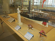
The Austrian Josef Ressel is one of the inventors of the propeller . In addition to John Ericsson and Francis Pettit Smith as well as Robert Fulton and David Bushnell , who was already experimenting with a propeller on a submarine, he was the one who brought the propeller to technical maturity. At that time it was also known as a ship's propeller because it was similar to the Archimedean propeller .
See also
- Ducted propeller
- Jet ring propeller
- Impeller
- Buckauer screw
- Wheel effect or screw effect : displacement of the stern of a ship due to the rotation of the propeller
- Rail zeppelin
literature
- Great Britain and Napoleon. Two new steamships with Archimedean propellers . In: Illustrirte Zeitung . No. 21 . J. J. Weber, Leipzig November 18, 1843, p. 332-335 ( books.google.de ).
- John S. Carlton: Marine propellers and propulsion. Butterworth-Heinemann, Oxford 1994, ISBN 0-7506-1143-X
Web links
- The development of the German propeller industry (1910–1990)
- Effects of the propeller on flight behavior. hagenheckel.de
- Propeller adjustment. hagenheckel.de, adjustment of the propeller blades on an ultralight aircraft
Individual evidence
- ↑ Effect on stability and control of a pusher propeller behind conventional tail surfaces as determined by tests of a powered model in the free-flight tunnel . Langley Aeronautical Laboratory, 1943; archive.org .
- ↑ a b Yamaha Operating Instructions, p. 444 ( Memento from August 13, 2014 in the Internet Archive )
- ↑ Counter-rotating twin propeller rc-network.de, April 22, 2002, accessed October 16, 2019.
- ↑ Order for German world market leader . In: Kölner Stadt-Anzeiger , August 9, 2011, p. 9.
- ↑ Charles Nicholl : Leonardo da Vinci. The biography. S. Fischer, Frankfurt am Main 2006, pp. 271-272, ISBN 978-3-10-052405-8 .


