
Drill


Drilling is a cutting manufacturing process that is used to manufacture holes . Since the geometry of the cutting edges of a drill is known, it counts in the classification of the manufacturing processes for machining with geometrically defined cutting edges , which also includes turning and milling . It is defined in DIN 8589 together with countersinking and reaming , which all have the same kinematics , i.e. have the same relative movement between tool and workpiece . With these three processes, the tool rotates around its own axis and also moves along this axis into the material . Countersinking and reaming is used as a more precise variant of drilling. However, these can only improve an existing hole, while drilling can also be used to drill into solid. In all three processes, internal surfaces are always created, which are often cylindrical, but always rotationally symmetrical . Both the hand tools and the machine tools are referred to as drilling machines .
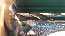
Drilling has been known since the Stone Age . However, the twist drills that are widely used today have only been around since around 1840. Before that, the spoon drill was used. When drilling, the cutting speed is greatest on the circumference of the tool and drops to zero towards the center. There the material is not cut, but pushed outwards from the tip. Drilling is one of the most important metal-cutting manufacturing processes. It is estimated that it accounts for around half of the total turnaround time, but this is also due to the fact that it is comparatively unproductive.
When drilling, a lot of heat is generated at the tip of the drill. Since the processing point is difficult to access, the heat generated there is just as difficult to dissipate as the chips generated there . The helix of the common twist drills is used to supply cooling lubricant on the one hand and to transport the chips away on the other. Most holes are about two to five times as deep as they are wide. Deeper holes are referred to as deep drilling , for which special deep drilling tools exist, since with twist drills chips and cooling lubricant would block each other.
When drilling, the tool usually rotates around its own axis and thus performs the cutting movement . The feed movement can take place by moving the drill or the workpiece. The workpiece is moved on pillar and column drilling machines , otherwise the tool. On lathes can also be drilled if the drilling axis coincides with the axis of rotation. There, however, the workpiece usually rotates around its axis and the tool only performs the feed movement. Internal turning , which is known as boring in English , is suitable for producing larger, rotationally symmetrical inner surfaces .
History of drilling technology
As early as the end of the Paleolithic ( Magdalenian ), pierced shells and animal teeth were worn as jewelry. In the Mesolithic (8300-4000 BC) bones and antlers , small pieces of jewelry made of stone, and occasionally stone disks were pierced. The stone drilling becomes the characteristic feature of the Neolithic . There are two types of drilling technology in rock:
- The "fake hole": Picking on both sides creates hourglass-shaped depressions that leave a double-conical hole.
- The "real bore" can be divided into the solid and the hollow bore.
The full drilling is done with a rotating drill head made of ivory, hardwood, stone or animal teeth. The characteristic is the V-shaped drill hole, which is created by the wear and tear of the drill.
Both techniques use water and an abrasive like quartz sand to create a more or less cylindrical recess. As experiments have shown, depths between 0.4 mm and 0.7 mm per hour can be achieved, depending on the raw material and drilling technique.
Lens drill
In the Near Eastern Natufia (12,000–9700 BC, at the same time as the European Magdalenian), lens drills were used to hollow out stone vessels (there was initially no ceramic production ). A flat, arched or conically tapering rotating diorite stone resulted in corresponding shallow or deeper bores with more or less steep walls. The drill head was connected to a shank forked at the bottom by means of two recesses. The drill head was rotated with the bowstring until the desired cavity was reached. A characteristic feature are the concentric rings that the drilling process leaves behind. The outer design of the vessel was done in a further work step by grinding.
Hollow bore
Hollow drilling (also tenon hole): is made with hollow wood such as elder or hollow stalks such as reeds , with hollow bones (which could be filled with sand as an abrasive) and a rapidly rotating drill rod. Vegetable drills can be used because the actual grinding work is done by quartz sand piled up around the drill. If the drilling is done from one side, a conical pin (drill core) falls out. A double-conical borehole is typical when drilling from both sides. Approx. 1/3 of the time is saved compared to full drilling.
Drill drives
The drill head made of bone, ivory or stone sits on the tip of a wooden stick. The rod rotates between the palms of the hands, the drill making several revolutions each time. A belt is looped around the boring bar with counter bearing (hand-held, hollowed-out stone) and pulled back and forth by two people, the drill rotating quickly. The drive of the boring bar by means of a bow (bow drill), which achieves a higher number of revolutions and speeds, is more effective. The wooden shaft with the drill head rotates in a counter bearing that is held by hand; with the other hand, the bow is moved back and forth, the cord simply wrapped around the wooden shaft causing the rotation. Presumably there was also the drill bit (racing spindle, Dreule). A cross handle attached to a cord and sliding up and down when turned turned the drill into a drill bit. The drill worked like the bow drill, except that instead of the roughly hand-sized abutment, a drill frame was erected, with a horizontal crossbeam with its weight constantly pressing on the drill shaft, which is driven by the cord of the bow, as with the fiddle drill.
Drilling or grinding media
Drilling or grinding media were mixtures of resin and fine quartz sand or quartz sand with the addition of water or the rock abrasion with water (stone grinding) that occurs during drilling.
Workpiece range and economic importance
Drilling makes up a large part of the machining time in mechanical engineering . However, this is also due to the fact that it is comparatively unproductive , i.e. it can remove little material per time (see metal removal rate ). The twist drill is the most frequently used tool in all of the machining technology.
Holes occur in numerous workpieces. These include through holes that are open on both sides and blind holes that are open on one side, as well as threaded holes and profile holes that deviate from the cylindrical shape. Centering holes are used to mark the center of workpieces in order to minimize dimensional deviations when reclamping on other machines. Most holes made by drilling have a depth of no more than five times the diameter. With deeper holes the tools bend, which leads to poor accuracy. With special deep drilling processes and tools, depths of up to 200 times the diameter are possible. Workpieces with bores are, for example, engine blocks , lock cylinders on door locks, brake cylinders , covers and housings on machines and pumps.

Through hole (left) and blind hole (right, lower component)
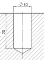
Blind hole

Threaded hole


Movements of tools and workpieces
In machining technology, a general distinction is made between two machining movements : the cutting movement or main movement, which leads to the cutting off of the chip, and the feed movement, which is responsible for continuous chip removal. When drilling, the tool usually rotates around its axis and simultaneously penetrates the workpiece along this axis. The rotating movement is the cutting movement, the other is the feed movement. The corresponding speeds are the cutting speed and the feed speed . There is always a right angle between the respective vectors when drilling; In the case of related milling, however, this angle changes constantly.
There are also variants of drilling in which the movements are completely or partially taken over by the workpiece:
- With upright drilling machines , the workpiece is on a height-adjustable table, above which the drilling tool rotates around a vertical axis. The workpiece is pushed into the drill from below; the feed movement is thus assigned to the workpiece.
- The workpieces rotate on lathes . Many have a device with which a non-rotating drilling tool can be pushed into the workpiece. So here the cutting movement is taken over by the workpiece.
- On automatic lathes and turning centers with a counter spindle, the workpiece is set in rotation and brought up to a completely stationary drilling tool. The entire machining movement is thus taken over by the workpiece. On these machines there is also a variant similar to that on ordinary lathes. In order to reduce the machining time, the tools also turn against the workpiece rotation in order to increase the cutting speed. For precision machining ( reaming ), the tool runs in the same direction as the workpiece but at a lower speed. This reduces the effective cutting speed without braking the workpiece, which would be disadvantageous for the turning operation taking place at the same time.
Definition according to DIN 8589 and differences to milling

Drilling is often defined as the (machining) production of holes or bores, but this can apply to many manufacturing processes, including internal turning and circular milling. In DIN 8589, there is an exact definition for all metal-cutting production processes, which is based on the terms cutting and feed movement and is preferred in the specialist literature. The drilling is summarized here with the countersinking and reaming because of the identical movement:
- Drilling, countersinking, reaming is machining with a closed circular cutting movement, in which the tool allows a feed movement only in the direction of the axis of rotation. The axis of rotation of the cutting movement maintains its position in relation to the tool and workpiece regardless of the feed movement.
This formulation leaves open whether the tools or workpieces move. The "closed" cutting movement refers to the fact that a cutting edge of the drill is again at the same point in the hole after one complete revolution - only a little deeper.
The related milling, on the other hand, is defined as follows:
- Milling is machining with a circular cutting movement [not closed] assigned to the tool and any feed movement. The axis of rotation of the cutting movement maintains its position in relation to the tool [but not in relation to the workpiece] regardless of the feed movement.
When milling, the tools always rotate and never the workpieces. In addition, the tools move laterally into the workpiece. A milling tool therefore always has its main cutting edges on the circumference and sometimes also secondary cutting edges on the face, while a drilling tool always has the main cutting edges on the face and never has cutting edges on the circumference (except for the very short secondary cutting edges near the head).
Chip formation and cutting edge geometry

Since the tools rotate around their own axis during drilling, the cutting speed changes over the radius: it is greatest at the circumference and falls to zero towards the center. Therefore, the chip formation is different across the cross-section, which is reflected in the relatively complicated shape of the drill.
- In the center of the hole, the material of the workpiece is pushed to the side by the cross cutting edge of the drill. The chip formation here corresponds to that when scraping , it is often referred to as "squeezing". The cutting edge is inclined in the direction of the cutting movement, so the rake angle is negative.
- The major part of the bore cross-section is removed by the main cutting edges. With twist drills they are inclined against the cutting movement, the rake angle is therefore positive, the cutting edges themselves are straight. In contrast, with indexable insert drills and some other drills, the angle is approximately zero. The chip formation here corresponds to cutting, as is usual with turning.
- The surface of the hole is created by the secondary cutting edges on the circumference of the drill. The place where the main and the minor cutting edge meet is the cutting edge corner. The cutting speed is greatest here and the mechanical and thermal loads are therefore greatest. At the same time, however, the corner of the cutting edge is loaded from two sides (from the main and secondary cutting edges). It therefore wears out the fastest, which is one of the reasons for the poor surface quality when drilling compared to other machining processes.
Chip formation during drilling is also scientifically investigated. One method is the so-called cut interruption, in which the process is suddenly interrupted, for example through predetermined breaking points in the tool. Then a cross-section through the hole together with the tool can be made by grinding and examined under the microscope. The shape of the chip root , the transition from the workpiece material to the chip, provides information about the chip formation mechanisms. Other methods are the FEM simulation which is used in modern construction, to identify different tool concepts promising that cinephotomicrography in the drilling with high-speed cameras will be filmed and the ring clamping investigation .
Special features of drilling in machining technology

Basically, the various machining processes have a lot in common. The following properties are considered to be characteristic of drilling:
- It is used exclusively for the production of interior surfaces.
- The diameter of the hole to be made is contained in the tool, only the depth is influenced by the movement of the tool. A different tool is therefore required for each diameter to be produced.
- The removal of the chips is difficult. The grooves of the tools are sufficient for short bores; for larger bores, they have to be flushed out with cooling lubricant .
- The heat is generated at the tip of the drill and can only be dissipated from there with difficulty. (See also energy conversion and heat during machining )
- The supply of cooling lubricant is problematic. With conventional twist drills, it takes place against the removed chips, so that blockages can occur. Other drills have channels inside for the coolant that comes out directly at the tip.
- The shank of the drill moves over the surface that has already been created, scratching it.
- The high wear of the cutting corners is typical for drilling. (See also wear (machining) )
- The cutting speed that changes over the cross-section of the tool. As a result, a built- up edge is almost always formed at one point on the drill , which leads to poor surfaces and tool life. With other methods, this phenomenon can be avoided by changing the cutting speed.
Achievable accuracies and surface qualities
With normal drilling, only very poor form, position and dimensional accuracy and surfaces can be achieved, which is why it basically counts as roughing (rough machining). In machining technology, drilling with attainable ISO tolerances of only IT15 to IT12 (with special measures also IT11) is the most inaccurate process. With the related countersinking and reaming, the usual accuracies of up to IT6 in machining technology can be achieved. With drilling tools made of solid carbide, tolerances such as countersinking can also be achieved; also with boring and spindles , two further drilling variants.
The surface qualities are usually specified as roughness. When drilling into solid with twist drills made of high-speed steel - standard tools and processes - the mean roughness depth R z is around 80 µm. On the other hand, when boring with a helical countersink, at 20 µm and when reaming at 8 µm. By turning, up to 4 µm can be achieved.
Classification of the drilling process according to the shape produced and the tools used (DIN 8589)

All machining processes are defined and classified in DIN 8589. Drilling, countersinking and reaming are dealt with together there because of the identical kinematics. The drilling processes are classified on the first level according to the shape created. They have a unique number that starts with 3.2.2 for all drilling processes (3rd main group: cutting , 2nd group: cutting with a geometrically defined cutting edge , 2nd manufacturing process: drilling).
- 3.2.2.1 plan cut : Serves what, but it is not possible to produce planar (flat) forms only by lowering by drilling.
- 3.2.2.2 Round drilling : For producing round shapes. It is further divided into solid drilling, core drilling and boring, which are further subdivided according to the tools used.
- 3.2.2.3 Screw drilling for the production of helical surfaces. The only way to do this is by tapping .
- 3.2.2.4 not used. (All machining processes are divided uniformly. The fourth sub-item is reserved for hobbing (e.g. generating turning , hobbing or gear shaping ) and is used to produce gears. This is not possible with drilling, so the order number is not applicable.)
- 3.2.2.5 profile drilling is used for the production of rotationally symmetrical profiles. The most important thing the center-drilling .
- 3.2.2.6 Form drilling . The cutting and feed movement is controlled here in order to produce non-circular shapes.
Round drilling
Round drilling is used to produce cylindrical inner surfaces that are coaxial with the axis of rotation of the tool. It bears the order number 3.2.2.2 and is divided into the four methods of drilling into solid, core drilling, boring and round reaming. The last two methods enlarge or improve an existing hole.
Drilling into solid
The drilling into solid (ON 3.2.2.2.1) is defined as a rotary drilling in the full material, so without pre-existing hole. The material is removed over the entire cross-section, while a core remains in the center of the hole when core drilling. It is further subdivided according to the tools used. Tools with symmetrical or asymmetrical cutting edges are used as standard. Single-lip drills and drill heads are used for particularly deep ( deep drilling ) or precise holes.
- 3.2.2.2.1.1 Drilling with symmetrically arranged main cutting edges , including twist drills , which are among the most common cutting tools .
- 3.2.2.2.1.2 Drilling with asymmetrically arranged main cutting edges , including indexable insert drills with cutting edges made from indexable inserts .
- 3.2.2.2.1.3 Drilling with a single-lip drill
- 3.2.2.2.1.4 Drilling with a drill head using the single-pipe method , better known as BTA drilling . The name of the manufacturer is avoided in DIN.
- 3.2.2.2.1.5 Drilling with a drill head according to the double pipe system , better known as ejector deep drilling .

BTA drilling
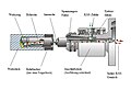
Ejector drilling

Drilling with a single-lip drill


Core drilling
Core drilling (ON 3.2.2.2.2) is drilling with an annular cross-section. A cylinder remains in the center of the bore that can be processed further. In industrial production, core drilling is used to reduce the volume to be machined in holes with a large diameter. It is used in civil engineering and geology to take rock samples that can be analyzed later.
- 3.2.2.2.2.1 Drilling with symmetrically arranged main cutting edges
- 3.2.2.2.2.2 Drilling with a single-lip drill
- 3.2.2.2.2.3 Drilling with a drill head using the one-pipe system
Boring
Boring (ON 3.2.2.2.3) is used to enlarge the diameter of an existing hole. In castings holes may be included by the nuclei were produced. However, these are not particularly precise, so that they get their final shape by boring. Further reasons for boring are the limited performance of the machines available and the accuracy that can be achieved. When drilling into solid, the cutting speed at the tip of the drill is zero. There the material is not cut, but pushed to the side. This results in large feed forces. These fall away when reaming. In addition, drills with a large diameter tend to run off when drilling into the solid. That is why such holes are usually pre-drilled with a smaller drill. For boring there are special boring bits with missing cross cutting edge, a larger core and usually more than the usual two cutting edges.
- 3.2.2.2.3.1 Boring with symmetrically arranged main cutting edges
- 3.2.2.2.3.2 Boring with asymmetrically arranged main cutting edges
- 3.2.2.2.3.3 Boring with a single-lip drill
- 3.2.2.2.3.4 Boring with a drill head according to the one-pipe system
- 3.2.2.2.3.5 Boring with a drill head according to the double pipe system
Round rubbing
Round reaming (ON 3.2.2.2.4) Used to improve the form and dimensional accuracy of cylindrical bores. The positional accuracy can no longer be improved. It is divided into multi-edged and single-edged circular rubbing.
Screw drilling
Screw drilling is used to produce helical workpieces. The only variant is tapping . A special tap is used to cut a thread into a hole whose diameter corresponds to the core diameter of the thread . Larger internal threads can also be produced by circular milling (a variant of screw milling ) or thread turning .
Profile drilling

With profile drilling, rotationally symmetrical surfaces are created that are not cylindrical like with round drilling. The profile of the hole is contained in the shape of the main cutting edges of the profile drill . There are standardized profile drill as the center drill and NC spotting for centering . Most of the other tools are custom made. Important profiles are countersinks for screw heads and conical bores, which are used for tool holders on various machines. Their machine interface is often designed as a Morse taper , steep taper or hollow shank taper . Profile drilling bears the order number 3.2.2.5.
- 3.2.2.5.1 Profile drilling into solid : A profile tool is used here to drill into solid. These include the center drills.
- 3.2.2.5.2 Reaming a profile : Used to enlarge a hole with a profile tool. Is used, for example, for tool holders or for holding taper pins .
- 3.2.2.5.3 Countersinks : used for the contact surface of tapered screw heads .
- 3.2.2.5.4 Profile rubbing : To improve dimensional accuracy and surface quality. Used for tool holders.
Form drilling
Form drilling with the order number 3.2.2.6 is used to produce any shape that does not necessarily have to be rotationally symmetrical. The only variant is non-circular drilling, in which the cutting and feed movements are controlled separately.
Special procedure
Hard drilling
Hard drilling is a variant of hard cutting and was developed in the 1980s together with hard turning and hard milling. In hard machining, workpieces are machined with a hardness of about 54 HRC upwards. Previously, such workpieces could only be machined by grinding or lapping . The Hartzerspanen generally has higher removal rates on, so it is much more productive. Since grinding can be omitted, since hard cutting is sufficiently precise, the process chains can be shortened, which leads to reduced costs.
Hard drilling is used to drill holes in hardened gears , flanges , dies or tools. There are special drills with a special tip for hard drilling: The cross cutting edge is significantly smaller, it is often S-shaped with a spiral point or cross point . The wedge angle is significantly larger.
The workpieces can be processed directly in the hardened state. This means that both soft annealing and grinding are not required , which also results in shorter throughput times . In addition, the expensive grinding machines can be dispensed with, as machining takes place on the cheaper lathes instead. Hard turning is also more economical, as a larger volume of material can be removed per time (larger metal removal rate). Since the workpiece shape is controlled by the movement of the tool during hard turning, it is also more flexible than grinding, in which the workpiece shape is usually partially contained in the tool. Because of the greater chip thickness , hard turning requires less energy and can also be used with little or no environmentally harmful cooling lubricant , which is known as dry machining or minimum quantity cooling lubrication .
High speed drilling
The high-speed drilling is a variant of the high- speed cutting (eng. High speed cutting). It is also known as HSC drilling or High Speed Drilling (HSD) and enables shorter machining times, better surfaces and reduced cutting forces. Disadvantages are the higher wear and the higher demands on the machines ( HSC drilling machines ).
Cooling lubricants

Cooling lubricant (KSS) is intended to reduce friction and dissipate the heat and chips that arise during drilling. This keeps the drill edge-holding longer until it has to be sharpened again due to wear, and increases the surface quality of the hole. So cooling lubricants have three tasks when drilling:
- Rinsing out the cuttings (chips, drilling mud, Schmant)
- Dissipation of frictional heat
- Reduction of the friction between drill and workpiece
Different cooling lubricants are used for the different materials to be drilled:
- Cutting oil or a cooling lubricant emulsion (with water) is often used for steel .
- Due to the graphite contained in the material , which is a solid lubricant , gray cast iron is usually drilled without additional coolant.
- With aluminum , alcohol has also proven its worth. Petroleum is a less flammable alternative with comparable results.
- Wood and plastic are usually drilled dry.
- A mixture of water and so-called compounds is used for rock . These are plastics to which additional fillers or reinforcing materials have been added.
Often, cooling lubricants are introduced by minimum quantity lubrication or completely replaced by dry machining. Twist drills and indexable insert drills often have an internal coolant supply; ie the cooling lubricant is fed through small bores in the drill shank onto the actual tool cutting edge. This increases the tool life, especially with greater drilling depths.
Drilling tools
There are many different tools for drilling. They are made from a single material - mostly high-speed steel or hard metal - or with inserted indexable inserts . Some have interchangeable tips - the interchangeable crowns. Most have two symmetrical cutting edges, but there are also single-edged, multi-edged and some with asymmetrical cutting edges.
By far the most important drilling tool is the twist drill . It has a share of 20 to 30% of all cutting tools and has two symmetrical cutting edges as well as spiral grooves that serve to supply cooling lubricant and remove chips. It is available in high-speed steel or carbide and with interchangeable heads. Different cutting edge shapes allow adaptation to the workpiece material.
There are also special tools for deep drilling, boring bars with only one blade for spindles , core drills, center drills, taps and profile drills which also include the center drill. In a broader sense, countersink drills and reamers are also among the drilling tools.
machinery

As drills are both mechanically driven hand tools called the machine tools . The hand drills usually have an electric motor as a drive and are held in the hand. On the machine tools, the relative movement between tool and workpiece is generated by the machine itself. The most important types are the pillar drill with a moving tool and the drill press with a moving workpiece. Both have a vertically hanging spindle in which the tool is located. The workpiece is underneath. On radial drilling machines , the spindle is on a boom that can rotate around a column. The spindle can be moved radially and thus quickly positioned. In coordinate drilling machines, the spindle can be moved along three independent linear axes. With horizontal boring machines , the tool moves horizontally and the workpiece is clamped vertically. There are also special machines for deep drilling, HSC drilling and fine drilling.
Drilling can also be carried out on machines that are actually intended for other processes, provided they have additional equipment for drilling. This applies in particular to machining centers , turning cells and automatic lathes .
Norms
In the specialist literature, the following standards are identified as important for drilling. These contain guide values and comments on drilling and the conditions to be taken into account.
- VDI 3210 Part 1: Deep drilling method
- VDI 3208: Guide values for deep drilling with a single-lip drill
- VDI 3209 sheet 1: Deep drilling with external infeed
- VDI 3334 sheet 1: Machine internal thread production - general, fundamentals, processes
- VDI 3388: Materials for cutting and forming tools
- VDI / VDE 3906: Precision engineering materials; Tool steels
- VDI 3035: Design of machine tools, production systems and peripheral equipment for the use of cooling lubricants
- VDI 3397 sheet 1: Cooling lubricants for cutting and forming manufacturing processes
- VDI 3397 sheet 2: Maintenance of cooling lubricants for the treatment and processing of metals - measures for quality maintenance, waste and wastewater reduction
- VDI 3397 sheet 3: Disposal of cooling lubricants
Other methods of drilling holes
There are a number of non-cutting manufacturing processes that can also be used to produce bores for special applications . These are either erosive or dividing processes which, according to DIN 8589, form independent groups of separating manufacturing processes. Formally, these methods are not assigned to the group of drilling methods according to DIN 8589. Examples of this are drilling erosion , a special form of spark erosion, a thermally ablative manufacturing process, laser drilling and laser cutting , also thermally ablative processes in which workpieces are processed with laser beams, and water jet cutting .
See also
- List of machining processes
- Chip formation
- Machinability
- High speed machining
- Energy conversion and heat during machining
Individual evidence
- ↑ Dirk Biermann: General [for drilling] in: Uwe Heisel, Fritz Klocke, Eckart Uhlmann, Günter Spur: Handbuch Spanen. 2nd edition, Hanser, Munich 2014, p. 311.
- ↑ a b Wilfried König, Fritz Klocke: Manufacturing process 1: turning, milling, drilling. 8th edition. Springer, Berlin 2008, p. 454.
- ↑ Herbert Schönherr: Machining production. Oldenbourg, Berlin 2002, p. 151f.
- ↑ Heinz Tschätsch: Practice of machining technology. Process, tools, calculation. 11th edition, Springer Vieweg, Wiesbaden 2014, p. 82.
- ↑ Uwe Heisel, Fritz Klocke, Eckart Uhlmann, Günter Spur: Handbuch Spanen. 2nd edition, Hanser, Munich 2014, p.
- ↑ Albert Herscher: Single and multi-spindle automatic lathes in: Uwe Heisel, Fritz Klocke, Eckart Uhlmann, Günter Spur: Handbuch Spanen. 2nd edition, Hanser, Munich 2014, p. 133.
- ↑ Heinz Tschätsch: Practice of machining technology. Process, tools, calculation. 11th edition, Springer Vieweg, Wiesbaden 2014, p. 92.
- ↑ a b Heisel, Klocke, Uhlmann, Spur: Handbuch Spanen. Hanser, 2014, p. 23 f.
- ↑ a b Dirk Biermann: General [for drilling] in: Uwe Heisel, Fritz Klocke, Eckart Uhlmann, Günter Spur: Handbuch Spanen. 2nd edition, Hanser, Munich 2014, p. 311 f.
- ↑ Herbert Schönherr: Machining production. Oldenbourg, Berlin 2002, pp. 152-155.
- ↑ Wilfried König, Fritz Klocke: Manufacturing process 1: turning, milling, drilling. 8th edition. Springer, Berlin 2008, pp. 454–457.
- ↑ Berend Denkena, Hans Kurt Tönshoff: Spanen , 3rd edition, Springer, 2011, p. 12.
- ↑ a b c d Dirk Biermann: General [for drilling] in: Uwe Heisel, Fritz Klocke, Eckart Uhlmann, Günter Spur: Handbuch Spanen. 2nd edition, Hanser, Munich 2014, p. 312.
- ↑ Thomas Bruchhaus: High-performance drilling tools - The difference is in the detail in: D. Biermann (Ed.): Machining - processes, innovations, materials , 6th edition, Vulkan, 2012, p. 121 f.
- ↑ Herbert Schönherr: Machining production. Oldenbourg, Berlin 2002, p. 154.
- ↑ Berend Denkena, Hans Kurt Tönshoff: Spanen , 3rd edition, Springer, 2011, p. 9 f.
- ↑ Heinz Tschätsch: Practice of machining technology. Process, tools, calculation. 11th edition, Springer Vieweg, Wiesbaden 2014, p. 96.
- ↑ Herbert Schönherr: Machining production. Oldenbourg, Berlin 2002, pp. 188-191.
- ↑ Uwe Heisel, Thomas Stehle: Significance of machining technology in: Uwe Heisel, Fritz Klocke, Eckart Uhlmann, Günter Spur: Handbuch Spanen. 2nd edition, Hanser, Munich 2014, p. 311 f.
- ↑ Uwe Heisel, Fritz Klocke, Eckart Uhlmann, Günter Spur (eds.): Handbuch Spanen. 2nd edition, Hanser, Munich 2014, pp. 313-315.
- ^ Alfred Herbert Fritz, Günter Schulze (Ed.): Manufacturing technology. 11th edition. Springer Vieweg, Berlin / Heidelberg 2015, p. 317 f.
- ^ Alfred Herbert Fritz, Günter Schulze (Ed.): Manufacturing technology. 11th edition. Springer Vieweg, Berlin / Heidelberg 2015, p. 318 f.
- ↑ Dirk Biermann: Overview of the drilling process in: Uwe Heisel, Fritz Klocke, Eckart Uhlmann, Günter Spur (eds.): Handbuch Spanen. 2nd edition, Hanser, Munich 2014, p. 313 f.
- ↑ Eberhardt Paucksch, Sven Holsten, Marco Linß, Franz Tikal: Zerspantechnik - processes, tools, technologies , Vieweg Teubner, 12th edition, 2008, p. 153.
- ↑ Alfred Herbert Fritz, Günter Schulze (ed.): Manufacturing technology , Springer, 9th edition, 2010, p. 313 f.
- ^ A b Alfred Herbert Fritz, Günter Schulze (Ed.): Manufacturing technology. 11th edition. Springer Vieweg, Berlin / Heidelberg 2015, p. 319.
- ↑ Uwe Heisel, Fritz Klocke, Eckart Uhlmann, Günter Spur (eds.): Handbuch Spanen. 2nd edition, Hanser, Munich 2014, p. 315 f.
- ↑ a b c Herbert Schönherr: Machining , Oldenbourg, 2002, p. 148 f.
- ↑ a b Uwe Heisel, Fritz Klocke, Eckart Uhlmann, Günter Spur (eds.): Handbuch Spanen. 2nd edition, Hanser, Munich 2014, p. 315.
- ↑ Herbert Schönherr: Machining , Oldenbourg, 2002, p. 200 f.
- ↑ Herbert Schönherr: Machining , Oldenbourg, 2002, p. 127.
- ↑ Herbert Schönherr: Machining production. Oldenbourg, Berlin 2002, pp. 197-200.
- ↑ Manfred Berger: HSC machines (Chapter I.6.7.6) in: Uwe Heisel, Fritz Klocke, Eckart Uhlmann, Günter Spur: Handbuch Spanen. 2nd edition, Hanser, Munich 2014, pp. 382–384.
- ↑ Jürgen Fronius: Tools and tool holders in: Uwe Heisel, Fritz Klocke, Eckart Uhlmann, Günter Spur: Handbuch Spanen. 2nd edition, Hanser, Munich 2014, pp. 322–333.
- ↑ Herbert Schönherr: Machining production. Oldenbourg, Berlin 2002, pp. 159-177.
-
↑ Uwe Heisel, Fritz Klocke, Eckart Uhlmann, Günter Spur (eds.): Handbuch Spanen. 2nd edition, Hanser, Munich 2014:
- Dirk Biermann: Machines and Systems , pp. 315–317.
- Rocco Eisseler: Column drilling machines , pp. 344–346, radial drilling machines , pp . 346–350, coordinate drilling machines , pp . 360f.
- Ulrich Straub, Ralf Müller: Feinbohrmaschinen , pp. 350–359.
- ^ Andreas Hirsch: Machine tools - basics, design, exemplary embodiments , Springer, 2nd edition, 2012, pp. 232–240.