
Turning (process)


The rotation is common with the drilling , milling and grinding of the most important manufacturing processes of machining technology . As with all of these processes, chips are cut from a workpiece to create the desired shape. When turning, the workpiece - the turned part - rotates around its own axis, while the tool - the lathe chisel - moves along the contour to be generated on the workpiece . The corresponding machine tool is a lathe . There is no purely manual variant such as grinding and drilling, but the tool can be operated by hand with softer materials. In principle, all machinable materials can be turned . Special features for turning wood can be found under turning . Professions that deal with turning are the wood turner and the lathe operator, who has since been replaced by the cutting machine operator together with the milling cutter . Companies or departments of companies that are mainly dedicated to turning are called turning shops .
Since all angles and radii of the cutting edge are known for turning tools , turning belongs to the group machining with a geometrically defined cutting edge , which also includes drilling and milling.
Turning has been known since ancient times and was important during the industrial revolution for the production of predominantly round parts such as screws and spindles for the textile industry. Today it is used for the production of axles , shafts and flanges as well as generally rotationally symmetrical parts.
The achievable accuracies in terms of dimensions, shapes and surface roughness are comparatively good, as with most machining processes. After turning, the workpieces are either ready for installation or only have to be finished by grinding.
Turning is divided into numerous process variants. If the turning tool is moved parallel to the axis of rotation of the workpiece (turning or turning), cylindrical shapes are created. If, on the other hand, it is moved perpendicular to the axis of rotation, flat shapes result (face turning). There are also variants for thread production or for any rotationally symmetrical shape (e.g. cones or balls). Profile turning with tools that contain the shape to be produced as a negative is suitable for larger series. In addition to outer surfaces, inner surfaces are also turned on hollow bodies. The clamping devices used for turning are typical of the process and are rarely used anywhere else. These include lathe chucks , collets and centering points .
The general basics of cutting technology apply equally to the cutting manufacturing processes, so that turning has no special features with regard to lathe tool wear, tool life, energy conversion and heat. For this see wear (cutting) , tool life (cutting) and energy conversion and heat during cutting .
Definitions


Turning is often defined as a metal-cutting manufacturing process in which the workpiece generates the cutting movement through its rotation and the (single-edged) tool generates the feed movement . This definition is correct in almost all cases. It can serve as an initial overview of the processes and as a demarcation from milling . In contrast, milling is defined as a process in which the (mostly multi-edged) tool rotates and the workpiece is stationary.
In contrast to this definition, generating turning and peeling turning are special variants in which the tools rotate. With generating turning, the tool rotates with the feed movement perpendicular to the workpiece in order to reproduce its profile on it, and with peeling turning the (multi-edged) tools rotate as a whole around a stationary workpiece. The main difference to milling is that when turning, the axis of rotation of the cutting movement is identical to the axis of symmetry of the workpiece, while this axis of rotation lies in the tool during milling. In DIN 8589, which defines all machining processes, the following is therefore:
Turning is machining with a closed (mostly circular) cutting movement and any feed movement in a plane perpendicular to the cutting direction. The axis of rotation of the cutting movement maintains its position in relation to the workpiece regardless of the feed movement.
This definition is also often found in the specialist literature. It is usually linked to the fact that in industrial practice the workpiece almost always performs the cutting movement. With oval turning, there is a variant in which the cutting movement is not circular, but is still self-contained.
In the English-speaking world, turning (literally: "turning") only means external turning. Internal turning is called boring . Both processes are sometimes referred to as lathe processes (literally: "lathe processes"); However, this also includes drilling, since drilling can also be carried out on a lathe without additional equipment.
history
Turning is a very old manufacturing process that dates back to the Bronze Age . With drilling , grinding , sawing and scraping , however, there are a number of machining processes that have been known since the Stone Age . The first machines existed for drilling and grinding . At about the same time as the turning, the filing and rasping were also created ; Within machining technology, only milling is more recent, and it originated in the 19th century.
In the Middle Ages , there were a number of improvements to the lathes that increased productivity. In the 17th century, turning became popular in the arts and crafts, and in the 17th and 18th centuries there were innovations in watchmaking and precision mechanics , which increased accuracy and were also adopted in general mechanical engineering in the course of industrialization . Parts were turned for steam engines , the railroad , textile machines and other machine tools . Important parts were screws and spindles, which were needed in large numbers. In the course of the 20th century, turning was further automated, first by electrical controls and then by CNC controls .
antiquity

Turning changed in the last millennium BC. Developed from drilling and is known to the cultures around the Mediterranean and the Ancient Orient , as shown by workpieces preserved from this period that come from the Etruscans , but also from Bavaria. A figure on the tomb of the Egyptian priest Petosiris from the 3rd century BC. Chr. Shows turning with a pull cord lathe . A worker alternately pulled both ends of a cord that wraps around a workpiece with his hands, so that the workpiece rotated left and right. A second worker ran the tool. They were mainly used for processing wood as well as ivory , horn, alabaster and bronze. The machines consisted of a roughly knee-high frame in which a vertical spindle, on which the workpiece was located, could turn. Work was done while crouching, which was the usual way of working at the time. The tools were probably made of bronze.
Spread to Europe
From Egypt, turning spread to the Babylonians , Assyrians, and Phoenicians . The latter had trade ties with the Greeks who passed the turning on to the Romans . The Celts have demonstrably mastered turning since the 7th century BC. And passed it on to the Germans . Twisted Germanic wooden feet are from the 3rd century BC. Proven. The Roman Vitruvius mentions in his 24 BC Chr. Incurred factory De Architectura "two-made on a lathe axis in a wooden frame" (Vitr. 10.15.4). What the Roman lathe looked like is not known. The only surviving illustration on a sarcophagus from the 2nd century shows only a fragment. The machine was powered by a fiddle bow and had a flywheel . Oreibasios , a personal physician to an emperor, is said to have turned iron nuts in AD 382.
middle Ages

In the 13th century, turning was simplified by the advent of the rocker lathe , which could be operated by a single person. One end of the cord was attached to a pedal and the other end to a springy slat. The oldest illustration is from a French Bible moralisée from the 13th century, which shows a working nun. In the 15th century cranks were used to drive lathes for metalworking. This drive enabled the workpiece to rotate continuously in one and the same direction. This enabled better power transmission. The master had both hands free to hold the tool and was able to achieve better surfaces. However, one needed an assistant to operate the crank again.
Video: Turning on a replica of a rocker lathe

Art turning from the 16th to the 18th century

In the 16th century handicrafts flourished and with it art turning. It was even popular in aristocratic circles. Emperor Maximilian I owned a particularly richly decorated lathe from 1518. The French Charles Plumier wrote a book in 1701 with the title L'art de tourner (“The art / technology of turning”). In the foreword he explained: "In France, Italy, England and Germany, the occupation with turning is so highly valued that there should hardly be people of spirit who do not try to excel with this art [...]" He demonstrated a lathe for Oval turning that could copy workpieces with the help of a template . Another lathe shown there, but not implemented, is suitable for thread cutting. As before, mainly non-metallic materials and occasionally very soft metals such as tin were processed . The machines were also still made of wood.
Precision mechanics and watchmaking in the 17th and 18th centuries
In precision mechanics and especially in watchmaking, very highly developed machines were used in the 17th and 18th centuries, which were only used in general mechanical engineering about a century later in the course of industrialization. Precision mechanics required high dimensional accuracies for the workpieces, which mostly consisted of copper alloys ( brass and bronze ). The machines and workpieces, however, were very small and could therefore consist of expensive metal throughout. Tool holders were attached to the machines that could be moved using cranks and thus allowed much more precise workpieces. With gears you could also couple the tool movement to the speed and thus produce almost identical screws with even threads.
In the 17th and 18th centuries, the machines, tools and processes of the craft were also scientifically examined and described for the first time. The relevant subject was called technology in Germany and taught to future administrative officials in order to enable good economic development. Christoph Weigel the Elder described in his book Illustration of the Common Useful Main Stands from 1698 numerous artists and craftsmen. An illustration shows a woodturner on a lathe with a foot lever. Gold, silver, brass, bone , wood and gemstones are named as materials. In France, the trades were described, among other things, in the Descriptions des arts et métiers by Réaumur and the Encyclopédie by Diderot . Among other things, you can see a tool holder for the watchmaker's lathes.
Industrialization in England
The physicist Johann Heinrich Moritz von Poppe mentioned in his book History of All Inventions and Discoveries around 1837 “Artistic lathes, figurative benches and other lathes”, which had been invented since the middle of the 18th century, and especially the “screwdriver lathes and screw cutting machines”.

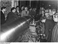
The general use of the tool holder, which was known from precision mechanics, made turning work much easier. The tools were now clamped in the machine and moved using handwheels. On the one hand, this reduced the force that the worker had to exert on the tool and, on the other hand, the demands placed on his skill. James Nasmyth described the lathe tool holder as one of the most important innovations in mechanical engineering. In his essay from 1841 - one of the very first essays on machine tools - there is a picture often shown in modern literature that compares turning in 1800 (without tool holder) with turning in 1840. While the older worker is straining to hold the tool with both hands on his wooden lathe and has to brace himself against it, the worker from 1840 stands casually in front of his machine with an iron frame and tool holder. The job is so easy that he only needs one hand to turn the handwheel that moves the tool slide.

During the industrial revolution in Great Britain, steam-powered lathes were built, which were of particular importance to industrialization. At first, it was primarily used to manufacture parts for textile machines and screws. Millions of spindles for textile machines were needed. In the middle of the 18th century, the work pieces consisted more and more often of iron materials ( wrought iron and cast iron , from around 1870 also steel ), which were much more difficult to machine. In order to increase the accuracy, the machines themselves were also made of iron. However, it depended to a large extent on the skill of the workers. The lack of suitable personnel and the great importance of turning for mechanical engineering led to an emigration ban for lathe operators in Great Britain in 1785 and an export ban for all machine tools , including lathes. In the early 19th century, the Briton Henry Maudslay , who is also considered the founding father of British machine tool construction, took over the numerous structural details of the lathes from precision mechanics to mechanical engineering. One of his first machines was a table lathe for making screws. The accuracy of the screws was no longer dependent on the skill of the worker. In addition, the various screws were so even that they could be interchanged with one another (so-called interchangeable construction ). Before, all screws were individual and each only fit into a thread belonging to it. It was only with Maudslay's improvement that the use of screws as fasteners became widespread. Previously, pens and wedges were the most common.
Industrialization in Germany and the USA
.jpg)
These innovations reached Germany in the context of industrialization with a delay of several decades (see also industrialization in Germany ). German officials made it easier to circumvent the export and emigration bans. They organized trips for German engineers and skilled workers to England, helped with customs duties and granted loans for the purchase of machines. In some cases, these were even procured at state expense and left to the companies, with the condition that these machines were shown to anyone interested in order to enable them to be reproduced. Lathes were particularly common. Bribes were also poured into the import of English machines. It was therefore an early form of industrial espionage . In 1835 19 of 129 German mechanical engineering companies also produced machine tools, including mainly lathes, drilling machines and gear milling machines.
Around 1870, the need for identical machine parts in America was particularly high in the context of the beginning industrialization there (see also: History of the United States # industrialization ). It was there that the automatic lathe was created for the first time , which independently took over the tool movement and changing tools. The machines could be operated by a trained assistant and only had to be set up by a specialist, which, among other things, concerned the selection of tools. The assistant fed in the raw parts, removed the finished workpieces from the machine and removed the chips. Above all screws were manufactured, so that the English name is screw machine (literally: " screw machine ") to this day . Other important machine parts were threaded spindles for textile or machine tools, spindles for spinning machines, shafts for power transmission as well as axles and wheels for steam locomotives .
Since 1900
In 1907 the American Frederick Winslow Taylor published the results of his ten-year research on machining technology in his book On the Art of Cutting Metals , which mainly deals with turning. To this day, research has regarded turning as the standard machining process. The material parameters for calculating the cutting force were determined during turning. For other methods, correction factors must be taken into account. Taylorism also originated from Taylorism and the high-speed steel introduced in 1907 , with which cutting speeds three times higher were possible. With the introduction of electrical control in the first half of the century, copy lathes and copy milling machines were also created that could capture a model with a button and electronically transmit its movement to the drives in order to copy workpieces. From the 1920s the drives of the machines were converted to electric motors . Older electric motors were not yet robust enough for industrial use.
From the 1980s onwards, CNC controls became generally accepted in cutting machine tools . With the machines known as CNC lathes , very complex shapes can be produced fully automatically, without having to make a model beforehand, as is the case with copy turning. Instead, all that remains is to load a suitable program into the machine's memory; the CNC control then guides the tool on the required path. Before the invention of the CNC control, lathes already had a very high (mechanical) degree of automation compared to other machine tools , so that it did not make much sense to want to increase this further. Nonetheless, CNC lathes made up well over half of all CNC machines for a long time. Due to large increases in productivity, their share finally fell to almost half, as fewer lathes were required for the same task. In addition, in combination with the corresponding measuring devices, higher levels of accuracy are possible, as required by customers. There were lathes with several tool slides that can machine a workpiece at the same time and thus in a shorter time. Turning centers have an automatic tool change, turning cells also have an automatic workpiece supply, so that the non-productive times for the change are reduced. Turning-milling centers can process the workpieces in a single machine by turning as well as milling and drilling, so that no additional machines are required. In conventional production, on the other hand, the turned parts have to be removed from the lathe and then clamped into the milling and drilling machines.
Importance and range of workpieces
Turning, together with drilling and milling, is one of the most important and most frequently used manufacturing processes in machining and manufacturing technology. The value share of cutting machine tools is relatively constant at around a third of the total production value of all machine tools. Around a third of this is accounted for by lathes or machining centers that are suitable for turning. The economic importance became evident at the latest in industrialization, when it would not have been possible to manufacture the numerous parts for steam and textile machines without turning and lathes. These parts, which are also required for modern machines, include axles , shafts , screws , threaded spindles , wheel hubs and small parts - today mainly for the automotive industry and general mechanical engineering, around 1900 especially for sewing machines and bicycles. Other parts produced by turning are chucks for turning, milling or drilling, rollers for rolling mills , various milling and drilling tools , lenses or mirrors for the optical industry. By fine turning (precision turning) are ball bearing components manufactured and pump pistons, synchronous gears , injectors , bearing bushes , standard parts , components of optical devices and instruments (pieces of eyepieces and objective ), housings for pumps, flanges , housing cover, and parts for drives hard disks.
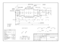
Drawing of a wave

Rotated chess pieces
Particularly large shaft in a lathe

Turbine part on a turret lathe with workers (top left) for size comparison

Wheels of a locomotive on a wheelset lathe

A flange

Cutter heads (milling tools)


_Steam_Locomotive_Construction_and_Maintenance_Fig30.jpg)


Achievable accuracies and surface qualities
Like most machining processes, turning is relatively precise. The workpieces are either ready for installation or only have to be reworked by grinding. As with almost all processes, the achievable accuracies depend on the dimensions of the workpieces and decrease with their size.
The achievable dimensional accuracy , specified as ISO tolerance that takes the influence of size into account, is usually IT10 to IT7 when turning (small numbers are more precise). IT6 can also be achieved with special measures. The dimensional accuracy when turning is therefore within the scope of what is common in machining technology. It is just as good for milling and broaching , worse for drilling (IT14 to IT12) and significantly better for grinding (IT9 to IT3, with special measures also up to IT1). With casting and forging as competing manufacturing processes, accuracies of around IT11 can be achieved, with special measures also IT8.
With fine turning or precision turning, accuracies from IT6 to IT7 can be achieved. High or ultra precision turning ranges from IT5 to IT01. With hard turning, the accuracy reaches up to IT5. With the usual workpiece dimensions, the dimensional deviations are therefore less than one micrometer.
The surface quality is usually measured as roughness . When turning, a trace of the tip of the tool can be seen on the surface. When turning, the roughness is less and therefore better, the larger the tip radius of the tool and the lower its feed rate. With roughing (rough machining) the roughness with averaged roughness depths of up to 100 µm, with finishing (fine machining) at 16 µm to 25 µm. With precision variants up to 3 or 4 µm can be achieved, which corresponds to an average roughness of about 0.15 µm.


Movements and speeds


In general, the is Spanungsbewegung differentiated according to the cutting movement, which leads to separation of the chip, and the feed movement, which provides for a continuous chip removal. When turning, the cutting movement is the rotational movement that is usually performed by the workpiece; only in rare cases do the tools rotate around the workpiece. The feed movement is usually the movement of the tool that can move parallel to the axis of rotation (longitudinal turning), perpendicular to it (transverse turning) or in a plane between these two directions of movement. On some special machines, the turned part is also shifted along the axis of rotation in order to carry out the feed movement while the tool is stationary.
The peripheral speed of the workpiece at the processing point corresponds to the cutting speed (from cut , cut) and is usually specified in m / min. In machining technology, all that matters is a relative movement between the workpiece and the tool. Which of the two active partners is moving and which is standing is of secondary importance. By convention, the vectors of the movements are displayed as if the tool were moving. When turning on conventional lathes, the cutting speed therefore points upwards, i.e. against the actual workpiece movement.

The speed in the feed direction is referred to as the feed speed (from English feed ), but it is of secondary importance. On the other hand, an important kinematic variable is the feed , i.e. the distance that the tool covers per revolution in the feed direction, usually specified in mm / revolution. The feed rate can be calculated from the speed and the feed rate. The angle between the cutting direction and the feed movement is commonly referred to as the feed direction angle (small Greek phi ). When turning (as well as drilling and other processes) it is a constant 90 °. When milling, on the other hand, it changes continuously during one revolution.


The resultant of the cutting speed and the feed speed is the effective speed . Your vector forms the effective direction angle with the vector of the cutting speed . In most cases, the effective speed corresponds approximately to the cutting speed in terms of amount and direction.

Turning process
The turning processes can be classified according to different aspects. The classification according to DIN 8589 is particularly common, which classifies on the first level according to the shape generated and therefore gives a good impression of the geometries that can be produced. Other important classifications are
- external turning and internal turning (machining of the inner surfaces of hollow bodies),
- the roughing (rough machining) and finishing (finish machining),
- taper turning for the production of conical shaped elements,
- hard turning for hardened workpieces,
- high-speed turning with particularly high cutting speeds.
Depending on the amount of cooling lubricant, a distinction is made between wet turning and dry turning and, according to the degree of automation , turning on conventional lathes, turning on CNC lathes or on automatic lathes .
Classification according to generated form (DIN 8589)
Probably the most important classification of the process variants can be found in DIN 8589 and is often cited in the specialist literature. All machining production processes are uniformly classified on the first level according to the shape created. In the case of turning:
- Face turning: production of flat (level) surfaces
- Round turning: production of circular shapes
- Screw turning: production of threads
- Generating turning: production of rolling surfaces (gear teeth)
- Profile turning: Production of any shapes with profile tools that contain the shape to be produced as a negative
- Form turning: Production of any shape through controlled tool movement
The further subdivision follows various criteria such as the tool movement (along or across the axis of rotation), the tools used or the type of movement generation (manual, machine).
All standardized processes and process variants have a serial number . In the case of the turning process, they all start with sequence 3.2.1. (3rd main group: cutting , 2nd group: cutting with a geometrically defined cutting edge , 1st process: turning).
Facing


When facing with the order number 3.2.1.1, flat surfaces are created that lie on the face of the turned part. The surfaces created are therefore perpendicular to the axis of rotation. A distinction is made between three variants:
- 3.2.1.1.1 With transverse facing, the tool moves perpendicular (transverse) to the axis of rotation. It is the most important variant and in practice it is also known as facing for short. It is usually carried out as the first step in order to generate a reference surface in the axial direction for further processing. Finishing (fine machining) usually works from the inside out, while roughing (rough machining) tends to work from the outside in. Cross facing is typical for machining on automatic lathes , where mostly small parts are manufactured off the bar. As with all transverse turning processes, it should be noted that the cutting speed changes at a constant speed. In conventional lathes and automatic lathes, it is kept within a range by means of a step gear, modern CNC lathes can achieve a constant cutting speed.
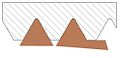
- 3.2.1.1.2 The cross-parting-off is used to cut off workpiece parts or to separate the entire workpiece from the bar-shaped raw material. The tools are very narrow in order to minimize material loss; however, they also tend to vibrate, which is referred to as chattering when machining . The tools have a main cutting edge that is oriented to the axis of rotation and two secondary cutting edges to the left and right of it. When grooving, the main cutting edge is not parallel to the axis of rotation ( tool setting angle is greater than 90 °). As a result, the connecting piece between the parts to be separated has the shape of a truncated cone during parting . In the final phase of machining, its tip tapers more and more until the workpiece is cut off without a residual pin.
- 3.2.1.1.3 With longitudinal facing , the tool moves parallel to the axis of rotation. The workpiece is hollow and the tool cutting edge is wider than the thickness of the workpiece. The resulting area is ring-shaped.


Cross facing

Cross parting off

Longitudinal facing


Turning
When turning with order number 3.2.1.2, round surfaces are created that lie on the surface of a cylinder whose axis coincides with the axis of rotation. A distinction is made between the five variants of longitudinal, flat finishing, peeling, longitudinal parting and transverse rotary turning. Longitudinal rotary turning in particular is of great importance and is used as a reference in standards and in specialist literature. This variant is often chosen in textbooks to explain basic terms and phenomena of machining technology. This variant is used for small parts in the watch industry as well as for the large-scale production of turbine barrels or drive shafts with lengths of up to 20 m.
- 3.2.1.2.1 With longitudinal rotary turning , the tool moves parallel to the axis of rotation. As the most important variant, it is referred to in practice as turning for short. It can be carried out with a wide range of different tools that are tailored to the respective requirements.
- 3.2.1.2.2 In the case of wide- finishing round turning or wide- finishing turning , a tool with a very large corner radius and a very small tool setting angle of the secondary cutting edge is used, whereby large feed rates are possible.
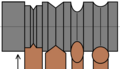
- 3.2.1.2.3 Peel turning, peeling rotary turning or peeling is a special variant of longitudinal rotary turning with a particularly high feed rate. This is usually achieved by using several tools at the same time, most of which have a small setting angle of the secondary cutting edge. The tools are usually arranged radially around the workpiece around which they rotate, while the workpiece only performs the feed without rotation. The bar peeling is often used to bright steel to manufacture, and is characterized by a high removal rate from. It is very productive and can produce very good surfaces. Feeds of up to 15 mm and roughness of = 2–10 µm can be achieved.
- 3.2.1.2.4 Longitudinal parting off is used to cut round slices from plates. It is very similar to profile turning and profile turning.
- 3.2.1.2.5 Cross-turning is a seldom used variant in which the feed movement is perpendicular to the axis of rotation and the tool is at least as wide as the surface created.


Longitudinal rotary turning
Wide finishing round turning

Peel turning

Longitudinal parting off turning

Cross turning


Screw turning

Screw turning with the order number 3.2.1.3 is used to create helical surfaces with profile tools. The shape to be generated is therefore partly contained in the shape of the tool. This variant is used to produce threads . The pitch of the thread corresponds to the feed (mm per revolution). Depending on the tools used, a distinction is made between thread turning, thread chasing and thread cutting. Screws , nuts and other mass- produced parts with threads are mostly manufactured today through more economical forming . Screw turning is only used to produce custom-made products or for threads that are located on workpieces that would also have to be machined without a thread.
- 3.2.1.3.1 Thread turning is screw turning with feed parallel to the axis of rotation with a simple profiled tool, the thread turning chisel or the thread turning inserts. With a transition of the tool, only part of the depth of the thread is generated, so several transitions with one infeed are necessary. A distinction is made between tools with a partial profile, which can only create the depth of the thread, but not the outer diameter, and tools with a full profile, which can also create the outer diameter. With thread turning, left-hand and right-hand or multi-start threads can be produced. In conventional lathes, the feed movement is mechanically linked to the rotation of the workpiece. The lead screw is used for this on traction and lead screw lathes. The pitch of the thread can be adjusted via exchangeable gears. A lead cartridge (spare lead screw) is used instead on automatic turret lathes. On CNC machines, on the other hand, the feed is electronically linked to the rotation of the workpiece.

- 3.2.1.3.2 With thread chasing , a multi-profile thread chaser is used in which the infeeds are integrated in the tool. Therefore, only one transition is necessary. The feed movement also runs parallel to the axis of rotation. With thread chasing, several profiles are used at the same time. With thread chasers a distinction is made between flat and round thread chasers. The latter is designed as a thread itself so as not to destroy the thread to be generated. It is preferably used for the production of internal threads. To produce a left-hand thread, a chaser with a right-hand thread must be used and vice versa.

- 3.2.1.3.3 Thread cutting uses a thread cutting die for manual production or a thread cutting head on CNC machines that moves parallel to the axis of rotation. The tools have several cutting edges that are distributed radially over the circumference. It is usually carried out with a stationary workpiece and a rotating tool. The kinematics of thread cutting is similar to screw broaching .
- 3.2.1.3.4 The tapered threading is a newer process with feed obliquely to the axis of rotation and with a threaded rotary tool for producing tapered threads.
- 3.2.1.3.5 The spiral turn is related to the cross-facing and also has a feed movement, perpendicular to the axis of rotation. A profiled turning tool creates a spiral surface on the face of the workpiece. This surface can have a groove or an elevation. The feed per revolution corresponds to the pitch of the spiral.
Thread turning: Left with partial profile tool, right with full profile
Thread chasing: Comparison of the tool geometry with the finished thread


Generating turning
Generating turning has the ordinal number 3.2.1.4 and is used to manufacture rotationally symmetrical rolling surfaces . These typically include gears . In generating turning, the tool performs a rolling movement that is superimposed on the feed movement. Gears which are non-rotationally symmetrical, such as racks , can be with the hobbing , Wälzhobeln or gear shaping produce.
Profile turning

With profile turning, the shape to be generated is contained in the shape of the tool as a negative. It bears the order number 3.2.1.5 and is used to produce rotationally symmetrical shapes. The tools are mostly custom-made, in which the desired shape is ground into a tool made of high-speed steel or hard metal. Harder cutting materials are difficult to grind. An exception are the standardized tools for grooves, undercuts or round profiles, as well as the grooves for sealing rings or retaining rings .
Profile turning is very productive and has short machining times, even for more complex shapes. The tools for this are generally more expensive.
A distinction is made between longitudinal and transverse profile turning as well as various grooving and parting processes:
- 3.2.1.5.1 Longitudinal profile turning uses tools whose cutting edges are at least as wide as the shape to be produced. These are moved parallel to the axis of rotation.
- 3.2.1.5.2 Longitudinal profile plunge-cutting is a special case of longitudinal profile turning, in which the tool is used to cut into the face of the workpiece in order to create an annular groove. However, the cutting edge does not have to be at least as wide as the shape created.
- 3.2.1.5.3 Longitudinal profile parting off is a variant of longitudinal parting off with a profile tool with which the workpiece is cut off and a profile is generated at the same time.
- 3.2.1.5.4 Cross profile turning corresponds to longitudinal profile turning, but instead the feed direction is perpendicular to the axis of rotation. The tools begin to rattle with chip widths from 15 mm to 30 mm .
- 3.2.1.5.5 Cross profile grooving corresponds to cross turning with a profile tool.
- 3.2.1.5.6 With transverse profile parting off, the workpiece is parted off like with cross-cut parting and a profile is generated at the same time as with cross-profile turning or cross-profile grooving.

Longitudinal profile turning

Longitudinal profile grooving

Longitudinal profile parting

Cross profile turning
Cross profile grooving

Cross profile parting off


Form turning

Shape turning creates any shape, such as spherical heads or cones. These shapes are generated by the feed movement of the tool. A distinction is made according to the type of movement generation in free-form, post-form (copy), kinematic and NC form turning. Form turning bears the order number 3.2.1.6.
- 3.2.1.6.1 With free-form turning , the feed movement is generated by hand. This can be done on conventional lathes using handwheels or without aids. According to DIN 8589, this expressly includes turning , which is mainly used to work with wood.
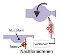
- 3.2.1.6.2 With postform turning , the feed movement is generated via a reference profile . This can be a template, a two-dimensional reference fitting or a masterpiece. It used to be called copy turning . As a further development, paths traveled once can be saved with electrical controls, which is referred to as teach-in .
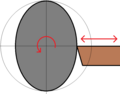
- 3.2.1.6.3 With kinematic form turning , the feed movement is controlled by a mechanical gear . This variant was used before the development of the CNC control (computerized numerical control) for the production of ball heads.
- 3.2.1.6.4 With NC form turning , the two feed axes (longitudinal and transverse to the axis of rotation) are driven by two separate motors that are controlled by a numerical control (NC). Today the variant of the CNC control is mostly used. This variant has been state of the art since the 1980s at the latest.
Postform turning

NC form turning

A linkage. A tool could be attached at point E.
Out-of-round turning


A variant of form turning not mentioned in DIN 8589 is out-of-round turning , with which, for example, an out-of-round or hexagon for screws or nuts can be produced. The tool moves periodically towards and away from the workpiece, coupled to the workpiece rotation. Oval turning , which was often used in handicrafts in pre-industrial times, also counts as oval turning .
Internal and external turning
Depending on how the machining point is located on the workpiece, one speaks of external turning or internal turning. With external turning, the outer surfaces are machined, with internal turning, surfaces that lie in a hole. The English term turning usually only refers to external turning ; internal turning is called boring .
Internal turning has some special features compared to conventional external turning. While the surface to be machined is bent away from the tool during external machining, it is bent towards it during internal machining. This results in a larger shear angle , which results in a greater cutting force . Since the tools used are usually very long and protruding, it is easier for them to vibrate and deflect. This leads to poorer surface quality and dimensional accuracy. The removal of the chips is also problematic. It is usually flushed out with the cooling lubricant that is injected into the bore under high pressure. The BTA-drilling uses a similar technique for chip removal.
Roughing and finishing
As with the other machining processes, a distinction can also be made between roughing (rough machining) and finishing (fine machining) when turning . With roughing, significantly more volume is machined per time than with finishing and consequently work with high cutting depths and feed rates. The machining forces are high, the achieved accuracy and surface quality play a subordinate role. The turned part is brought almost to size. In the subsequent finishing process, however, the desired dimension of the finished part is achieved. The machining forces are lower because the feeds and depths of cut are lower. However, the requirements for dimensional accuracy and surface quality are higher.

Roughing aluminum

Finishing (note the changed chip shape and thickness)


Taper turning
Taper turning creates shapes that correspond to those of a cone or a truncated cone . It is often used to manufacture conical shafts. In addition to general form turning, there are two ways of generating the form by longitudinal turning: inclining the top slide on the tool holder of the machine and moving the tailstock laterally when turning between centers .
The inclination of the top slide is initially done roughly using a scale. The fine adjustment is then carried out with gauge cones and a dial gauge . This variant is used for short cones with a large opening angle.
If the tailstock is moved laterally, the entire workpiece is inclined to the feed axes of the tool holder. If this is moved as in normal longitudinal turning, a cone is created automatically.
Hard turning
Hard turning is a variant of hard machining with which materials with a hardness of more than 54 HRC can be machined. Traditionally, this was only possible through grinding and lapping . The development of so-called super hard cutting materials (tool materials) such as cubic boron nitride made it possible to machine such hard materials by turning, drilling or milling , which leads to numerous advantages. Hard turning is basically also possible with silicon nitride cutting ceramics and coated hard metal , but the tools wear out faster.
The workpieces can be processed directly in the hardened state. This means that both soft annealing and grinding are not required , which leads to shorter throughput times . In addition, the expensive grinding machines can be dispensed with because machining takes place on the cheaper lathes. Hard turning is also more economical, as a larger volume of material can be removed per time (larger metal removal rate ). Since the workpiece shape is controlled by the movement of the tool during hard turning, it is also more flexible than grinding, in which the workpiece shape is usually partially contained in the tool. Because of the greater chip thickness , hard turning requires less energy and can be used with little or no cooling lubricant , which is known as dry machining or minimal cooling lubrication . Hard turning is used for more complex shapes, whereas long straight shafts can be machined more economically by grinding because the wider grinding wheels in this case have shorter machining times.
Typical values for hard turning are depths of cut of a p = 0.01 mm to 0.3 mm, feeds of f = 0.01 mm to 0.14 mm and cutting speeds of v c = 120 m / min to 220 m / min. They are therefore all well below those of conventional turning. Areas of application for hard turning are bearing seats for shafts and wheels, rolling bearing rings and rollers.
HSC turning
The high-speed rotation or short HSC turning (High Speed Cutting = high speed cutting ) is a variant of rotating with especially high cutting speeds. There is no clear demarcation; in the case of steel, cutting speeds from 500 m / min are referred to as HSC turning, in the case of aluminum only from 2000 m / min. Higher cutting speeds have a positive effect on productivity. They also lead to decreasing cutting forces, which is why high-speed machining is also suitable for filigree components. When turning, the high speeds lead to high centrifugal forces, which requires special machines. In addition, specially designed clamping devices must be used. With most of the machines available on the market (as of 2014), only the lower cutting speeds of HSC turning can be achieved. Because of the high speeds, flying parts such as chips pose a significantly increased risk to people and machines, which requires special safety precautions.
Fine and precision turning
According to the achievable accuracy, turning is divided into "conventional turning" (sometimes also in the sense of "turning without NC control"), fine turning or precision turning with attainable ISO tolerances from IT6 to IT7, high-precision turning (IT6 to IT2) and ultra-precision turning ( IT1 to IT01). The feed rate is reduced: with precision turning it is around 100 µm per revolution, with high-precision turning it is 10 µm and with ultra-precision machining it is only a few micrometers. The manufacture of optical devices and instruments (especially lenses and mirrors) is seen as the driving force behind improving accuracy. Diamond tools are typical for ultra-precision machining because of their low wear. Special ultra-precision lathes are used . Thanks to special design measures, these achieve high repeat accuracy . These include a main spindle with high rigidity, hydrostatic or hydrodynamic bearings for the spindle, special foundations and damping systems to reduce vibrations.
Steel and non-ferrous metals are particularly suitable as materials for precision turning . With ultra-precision turning, non-ferrous metals, plastic and monocrystalline materials are machined. Precision turning is also used in the form of hard turning for hardened materials as a replacement for grinding . The precision variants of turning be used for workpieces of the precision engineering , automotive industry , optics , medical technology , plastic - and light metal processing, electrical engineering , for watches and jewelry manufacturing. It can aspherical lenses and even non-rotationally symmetric lenses are made. For the latter, particularly dynamic feed drives are required, which are usually designed as linear direct drives . Hardened steel components are pump piston , synchronizing rings , fuel injectors , bushings , standard components , hydraulic pistons, gear shafts and ball bearing components. Housings for gasoline pumps , water pumps and ignition distributors as well as bearing covers for stepper motors , flanges for electric motors , wheel hubs and computer parts are made from light metals . Optical mounts are manufactured for precision mechanics, as well as lens housings, microscope components, copy rollers, photo components, video head drums and hard disk parts . Housing for pins, seals, bearing cages and water meter housings are made from plastic.
Chip formation

The development of chips has been particularly well researched for turning. At the beginning of the machining, the material is upset by the tool until the strength is exceeded. In hard, brittle materials such as cast iron or ceramics, cracks form, which spread until chunks detach from the workpiece and the process begins again. Most metals, especially steel, are ductile and can be deformed. A long chip forms and runs over the tool. Chip formation is continuous, which leads to slight fluctuations in the cutting force and thus to long tool life. However, the chips can get caught and endanger people and machines. So-called chip breakers are used to avoid this . These are edges on the tools that the chips run against and break. The length of the chips depends on numerous factors. The two most important are the material and the feed. With increasing feed, the chips become shorter and therefore cheaper.
Tools and cutting materials

The tools used for turning are usually referred to as turning tools. Sometimes, however, this only refers to tools that are made entirely of high-speed steel or have a soldered-on cutting edge made of the more expensive, but harder and more wear-resistant hard metal . When the cutting edges are worn, they are reground. In industrial practice, however, toolholders in which an indexable insert acts as a cutting edge are mostly used today . If the edge of the plate is worn out, it is turned or turned to use new edges and then replaced with a new plate. The plates are no longer reground.
There are special tools for external or internal machining, roughing and finishing, profile tools that contain a workpiece shape to be generated as a negative (including tools for thread turning), as well as grooving and parting tools and copying turning tools that are suitable for post-forming or NC turning .

Lathe tool made of HSS or hard metal

Tool holder for indexable inserts

Indexable inserts


The materials from which the cutting edges are made are referred to as cutting material in machining technology . The industrial standard is carbide, with which higher cutting speeds and thus lower processing times are possible than with conventional high-speed steel (HSS). When turning, however, the entire range of known cutting materials can basically be used. Cutting ceramics and cubic boron nitride are also used for materials that are difficult to machine . Diamond tools are particularly suitable for machining aluminum alloys and copper alloys because of their high wear resistance and the accuracy that can be achieved . However, they are unsuitable for steel because they transform into graphite at the high temperatures that occur .
machinery

The machines suitable for turning are mainly lathes and machining centers , which are suitable for both turning and milling. About a third of the production value of cutting machine tools is accounted for by lathes. They are absolutely necessary for turning - there is no manual variant such as drilling, sawing or grinding. The lathe is probably the most varied machine tool: It is available in numerous degrees of automation , sizes and different design concepts. Some are specially designed for a narrowly defined range of workpieces, such as the roll lathe (for the manufacture of rolls for rolling mills), wheelset lathes for the wheels of rail vehicles or the crankshaft lathe.
Lathes consist of several components: a drive, guides and bearings that enable the tools and workpieces to be moved, as well as the control and the frame to which all components are attached. This also includes the tool slide in which the tool is clamped, which usually has its own drive. As additional equipment there are steady rests and the tailstock to support long workpieces .
The simplest form of lathe is the universal lathe . Almost all turning processes are possible with it, including grooving, parting off and threading. It is suitable for a wide range of workpiece sizes and shapes, but is not very productive and is therefore only suitable for individual parts and small series. Universal machines make up the majority of all lathes and are particularly found in repair shops. The CNC lathe has a CNC control that directs the tool on programmed paths, making it suitable for small and medium-sized series and also enabling the production of complex shapes. If, instead of the tool slide, there is also a tool turret in which several tools are clamped, these are called turning centers . The tool change times are significantly shorter, which is why they are also suitable for medium to large series of workpieces. Automatic lathes are suitable for large-scale and mass production because they have several tool slides or turrets that are engaged at the same time. This makes them particularly productive, but converting to another product takes a relatively long time.
So-called vertical lathes are available for particularly large and heavy workpieces . There are precision lathes for precision machining of parts for precision mechanics . For high-speed turning, there are special machines that are designed for the high centrifugal forces.
Clamping device
In general, clamping devices are used to fix tools or workpieces during machining. The special feature of turning with its mostly rotating, round workpieces instead of the mostly stationary, prismatic workpieces, results in some special features of the clamping devices.
The tools themselves must be clamped in the lathe. Various interfaces have been developed for this. The shanks of the turning tools can either be round or square. They can be clamped directly in the tool slide or in a tool memory that contains several tools and can quickly exchange the machining tool. A hydraulic system is used for clamping during automatic tool changes.
There are numerous clamping devices for the workpieces that are specially designed for turned parts. The rotation of the turned parts results in centrifugal forces, especially at high speeds, which endanger the secure clamping of the workpieces. Standard clamping devices for turning are the chucks . These are generally suitable for rotating parts and, in addition to turning (lathe chucks), are also used for drilling or milling (drilling or milling chucks). They consist of two to eight clamping jaws that apply the clamping forces distributed around the circumference of the workpiece. With chucks, all clamping jaws are moved at the same time. They are suitable for hollow and solid workpieces, which are also referred to here as chuck parts . Lathe chucks are operated either manually (manual chuck) or hydraulically, electrically or pneumatically (power chuck). Similar to the chucks are the face plates in which the clamping jaws can be moved individually. Clamping takes longer, but they are also suitable for non-circular workpieces. For thin-walled, hollow rotating parts which would deform on chucks are suitable mandrels . These apply the clamping force evenly over the entire inner surface. Collets are suitable for turned parts with a smaller diameter in automated production, for example on automatic lathes . The set-up times are very short, but so are the clamping forces, so that they are not suitable for high speeds. In addition, the clamping range of a collet is only about 0.3 mm in diameter; only workpieces with a size within this range can be clamped. If workpieces of different sizes are to be machined, a large number of collets of different sizes are required.

Lathe chuck with six jaws
Segment mandrel

Various collets

Centering points


Lathe chucks, face plates, mandrels and collets clamp the turned parts around the circumference. Face drivers , center pins and rotary grippers are suitable for longer workpieces . These clamp on the end faces of the workpieces. On the one hand, this makes the entire length of the workpieces accessible for machining, which means that reclamping for rear-side machining can be dispensed with, which also increases the concentricity . On the other hand, the two ends of the workpieces are supported so that they bend less. Particularly long workpieces are additionally supported in the middle with a steady rest.
Turning parameters
The process parameters are the cutting speed in m / min, the feed rate in mm / rev, the cutting depth (also called infeed) and the various angles and radii on the cutting edge of the turning tool. For a given workpiece diameter, the cutting speed results from the speed . On CNC lathes , the cutting speed can be set, from which the control calculates the required speed. In addition, with CNC controls, programs can be created for similar workpieces by means of variable and parameter programming.
During machining, the process parameters lead to a certain cutting force and temperature on the tool, power consumption, vibrations and acoustic emissions (noise) and chip shapes . After machining, they are noticeable on the workpiece as the dimensions and surface quality achieved, as well as tool wear and the costs incurred. As with most machining processes, the most important process parameters are the feed rate, the cutting depth and the cutting speed.
In manufacturing technology, the basic principle is that the specifications required by the designer (dimensions, roughness, etc.) can be achieved as economically as possible. Since the costs increase with the accuracy, the following applies: Processing should only be as precise as necessary. An important technical productivity indicator is the metal removal rate , the volume of material separated per unit of time. It can be calculated from the cutting speed , the feed and depth of cut to


- .

The values should therefore be as large as possible. The individual values are, however, technically limited, as they lead to higher wear as well as higher forces and temperatures, and in some cases also to lower possible accuracies.
Cutting speed and speed
The choice of cutting speed depends on various factors. These are the material of the workpiece, the material of the tool ( cutting material ), the machining process ( roughing , finishing , fine finishing ), the turning process, the required surface quality of the workpiece and the cooling lubricant . The speed depends on the cutting speed and diameter of the workpiece and can be calculated using the formula .


An increase in the cutting speed increases the metal removal rate. For a given cutting material, however, it is also the main influencing factor on tool wear ( see wear (cutting) ). In general, the higher the cutting speed, the greater the wear. At low speeds, built- up edges can form. A part of the chip remains stuck to the cutting edge, which leads to increased wear and poor surface quality. An increase in the cutting speed also leads to slowly falling cutting forces, which is used in high-speed turning. The realizable cutting speeds are usually higher, the more wear-resistant the cutting material used is.
Guide values for the cutting speed can be found in the table books or the data sheets for the turning tools. Optimization can be achieved with the Taylor line .
Feed and depth of cut


The feed rate f is given in millimeters per revolution. For economic reasons, it should be set as large as possible when roughing. Increasing the feed also increases the cutting force acting on the tool. This can lead to vibrations and thus to decreasing accuracy. A higher force also leads to a higher power requirement (power = force × speed). Since the power of the drive is limited, the feed rate and the cutting depth are also limited at a given cutting speed. For the latter, the same applies as for the feed, doubling the feed increases the cutting force by less than twice, and doubles the cutting depth. The Kienzle formula offers a mathematical connection . When finishing (finish turning), the feed rate is reduced compared to the roughing process and the cutting speed is increased in favor of a higher surface quality. The smaller the tip radius of the turning tool, the lower the feed rate has to be set for a consistent surface quality. Theoretically, the roughness is around


- .

In addition, a minimum chip thickness that depends on the feed rate must be achieved. The ratio of minimum chip thickness to cutting edge radius when turning is between 0.25 and 1.125.

The depth of cut is dependent upon turning round from the delivery of the rotary tool, at the grooving of the width of the cutting edge. When roughing, the cutting depth should at least correspond to the size of the insert radius. A smaller cutting depth leads to a higher wear of the tool cutting edge in the area of the insert radius. In practice, the ratio of the depth of cut to the feed is around 10: 1, but it can vary depending on the spindle power, the clamping situation of the component, the material, the tool geometry and the cutting material. When finishing, the cutting depth corresponds to half the allowance.
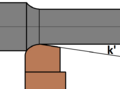
Angles and radii on the tool cutting edge

There are numerous angles and radii on the cutting edges of the cutting tools , which primarily influence the distribution and direction of the cutting force and wear. The radii also influence the accuracy that can be achieved.
Guide values
Guide values are values listed in tables, which allow an orientation in which areas economic process parameters can be expected. The following table gives a rough overview of the values used in practice and applies to roughing. When finishing, smaller depths of cut and feeds are used and slightly higher cutting speeds and other types of cutting material. It is easy to see that the realizable cutting speeds turn out to be higher, the more wear-resistant the cutting material and the lower the strength of the material. (The strength of aluminum alloys is lowest, that of alloy steel highest). The values that can actually be achieved depend on the alloy. The high cutting speeds of a line include the low feeds and cutting depths.
| Workpiece material | Cutting depth a p [mm] |
Feed f [mm / rev] |
Cutting material | Cutting speed v c [m / min] |
|---|---|---|---|---|
| Carbon steel | 2 to 8 | 0.3 to 0.6 | coated hard metal | 100 to 200 |
| Alloyed steel | 2 to 6 2 to 10 1.5 to 6 |
0.3 to 0.6 0.2 to 1 0.3 to 0.45 |
Hard metal (uncoated) coated hard metal cutting ceramic |
60 to 120 120 to 300 150 to 700 |
| Cast iron (gray cast iron) | 2 to 6 2 to 8 2 to 6 1.5 to 6 1.5 to 8 |
0.3 to 0.6 | Hard metal (uncoated), coated hard metal, coated cermets, aluminum oxide cutting ceramics, silicon nitride cutting ceramics |
60 to 100 100 to 250 200 to 300 100 to 400 200 to 800 |
| Aluminum alloys | 2 to 6 2 to 8 1 to 5 0.5 to 3 |
0.3 to 0.6 0.3 to 0.6 0.1 to 0.4 0.1 to 0.2 |
Tungsten Carbide Coated Tungsten Carbide Coated Cermets Polycrystalline Diamond |
150 to 1500 200 to 2000 220 to 2200 400 to 3000 |
error
Various errors that affect the tools or the workpieces can occur during turning. In the specialist literature there are detailed tables with possible errors, their causes and remedies.
Too high tool wear for example, is usually caused by excessive process parameters for the tools used. This can be remedied by reducing the parameters or using more wear-resistant tools.
Comb cracks on the tool are a form of wear caused by rapid temperature changes. This can be remedied by improving the cooling lubricant supply (more or more specifically) or switching off the cooling lubricant during an interrupted cut ( dry machining ), because rapid temperature changes can also be avoided through reduced cooling.
Low dimensional accuracy on the workpiece can result from worn tools, scratches on the workpiece from chips or from oxidation wear on the secondary cutting edge. High roughness on the workpiece results from high feed rates or small tip radii on the tool.
calculation
The forces, power and machining time that occur during turning can be calculated using the following equations. These values are required for the work preparation and the construction of the lathes.
Powers and achievements
The experimentally determined Kienzle formula is suitable for calculating the cutting force when turning . For other manufacturing processes, it is multiplied by a correction factor depending on the process. Knowing the cutting force, it can be checked whether the planned process parameters can be implemented on an existing machine, how great the deflection of the tools is or, in the construction of the machine, how great the torque of the drive must be or how strong the tools are designed have to.
The performance is the product of the speed and the force. The cutting performance, which corresponds approximately to the total performance, is the product of the cutting speed and cutting force. The performance can also be used to check whether the planned process parameters can be implemented on existing machines or how high the performance of the machines to be constructed must be.
Prime time
The main time when turning is the time when the chips are falling. It can be calculated. The non-productive time, on the other hand, during which tools or workpieces are changed and the tools perform various traversing movements without cutting off chips, depends on the machine. In industrial practice, the main time is calculated, estimated or determined by time determination (stop watch) by CAP systems . It is required for the calculation (calculation of the costs incurred), the machine occupancy time and the required number of machines in order to be able to produce a certain production quantity within the desired time.
If the process parameters during the entire processing are constant, the main time of the separated material volume results and the removal rate for


With longitudinal turning, the time can also be calculated with

There are:
- = Number of cuts
- = largest diameter
- = Path length that the tool has to cover (workpiece length + machining allowances + approach and overrun paths for the tool).
- = Feed
- = Cutting speed


See also
- Turning broaching - a combination of turning and broaching
- List of machining production processes - overview with definitions as well as associated machines, tools and achievable accuracies
Web links
literature
- International Academy for Production Engineering (Ed.): Dictionary of Manufacturing Engineering - Volume 2: Separating Processes. Springer, 2nd edition, 2004, ISBN 3-540-20540-3 .
- Uwe Heisel, Fritz Klocke , Eckart Uhlmann , Günter Spur : manual cutting. 2nd edition, Hanser, Munich 2014. ISBN 978-3-446-42826-3 .
- Wilfried König , Fritz Klocke: Manufacturing process 1: turning, milling, drilling. 8th edition. Springer, Berlin 2008, ISBN 978-3-540-23458-6 .
- Berend Denkena, Hans Kurt Tönshoff : Machining - Basics. 3rd edition, Springer, Berlin 2011. ISBN 978-3-642-19771-0 .
- Heinz Tschätsch: Practice of machining technology. Process, tools, calculation. 11th edition, Springer Vieweg, Wiesbaden 2014. ISBN 978-3-658-04922-5 .
- Eberhard Pauksch: Machining technology. 12th edition, Springer Vieweg, Wiesbaden 2008. ISBN 978-3-8348-0279-8 .
- Herbert Schönherr: Machining production. Oldenbourg, Berlin 2002. ISBN 978-3-486-25045-9 .
- Werner Degner, Hans Lutze, Erhard Smejkal: Machining. 17th edition, Hanser, Munich 2015. ISBN 978-3-446-44544-4 .
- Christian Gottlöber: Machining of wood and wood-based materials: Basics - Systematics - Modeling - Process design. Hanser, Munich 2014. ISBN 978-3-446-44003-6 .
Individual evidence
- ↑ Herbert Schönherr: Machining production. Oldenbourg, 2002, p. 67.
- ↑ Industrial manufacturing - manufacturing processes, measuring and testing technology. Verlag Europa-Lehrmittel, 5th edition, 2011, p. 231.
- ↑ Heinz Tschätsch: Practice of machining technology. Process, tools, calculation. 11th edition, Springer Vieweg, Wiesbaden 2014, p. 41.
- ↑ Quoted from: Uwe Heisel, Fritz Klocke, Eckart Uhlmann, Günter Spur (eds.): Handbuch Spanen. 2nd edition, Hanser, Munich 2014, p. 150.
- ↑ Uwe Heisel, Fritz Klocke, Eckart Uhlmann, Günter Spur (eds.): Handbuch Spanen. 2nd edition, Hanser, Munich 2014, p. 150.
- ↑ Reinhard Koether, Wolfgang Rau: Manufacturing technology for industrial engineers. Hanser, 4th edition, 2012, p. 146.
- ↑ Fritz Klocke , Wilfried König : Production Process Volume 1: Turning, Milling, Drilling. Springer, 8th edition, 2008, p. 417.
- ↑ Metal technology specialist training. Verlag Europa-Lehrmittel, Nourney, 2nd edition, 1993, p. 80.
- ^ Alfred Herbert Fritz, Günter Schulze (Ed.): Manufacturing technology. Springer, 9th edition, 2010, p. 289.
-
^ Liang, Shih: Analysis of Machining and Machine Tools. Springer, 2016, p. 4.
See also en: Turning and en: Boring (manufacturing) . - ^ Trent, Wright: Metal Cutting. Butterworth Heinemann, 2000, 4th edition, pp. 9, 12 f.
- ↑ Günter Spur: Production technology in transition. Carl Hanser, Munich / Vienna 1979, p. 36.
- ↑ Günter Spur: Production technology in transition. Carl Hanser, Munich / Vienna 1979, pp. 42, 45 f.
- ↑ Günter Spur: Production technology in transition. Carl Hanser, Munich / Vienna 1979, pp. 168, 286.
- ↑ A brief history of woodturning. ( Memento of the original from June 1, 2017 in the Internet Archive ) Info: The archive link was inserted automatically and has not yet been checked. Please check the original and archive link according to the instructions and then remove this notice.
- ^ Gustave Lefèbvre: Le tombeau de Petosiris, Troisième partie: vocabulaire et planches. Institut Français, Cairo 1923, planche X, PDF from archive.org, p. 423 (bottom left), accessed on March 2, 2017.
- ↑ Günter Spur: Production technology in transition. Carl Hanser, Munich / Vienna 1979, pp. 25, 39.
- ↑ Günter Spur: Production technology in transition. Carl Hanser, Munich / Vienna 1979, p. 39.
- ↑ Günter Spur: Production technology in transition. Carl Hanser, Munich / Vienna 1979, p. 39.
- ↑ Günter Spur: Production technology in transition. Carl Hanser, Munich / Vienna 1979, pp. 25, 39.
- ↑ Günter Spur: On the change in the industrial world through machine tools. Carl Hanser, Munich / Vienna 1991, p. 46.
-
↑ a b c Günter Spur: On the change in the industrial world through machine tools. Carl Hanser, Munich / Vienna 1991, pp. 46, 62, 66, 91, 115 f., 146, 201, 291, 308, 427.
Günter Spur: Production technology in transition. Carl Hanser, Munich / Vienna 1979, pp. 39, 56, 82. - ^ Franz Reber : Des Vitruvius ten books on architecture. Kraiss & Hoffmann, Stuttgart 1865, p. 347.
- ^ Roger B. Ulrich: Roman Woodworking. Yale Univ. Press, London 2007, p. 39.
- ↑ Günter Spur: Production technology in transition. Carl Hanser, Munich / Vienna 1979, p. 45.
- ↑ Bibliothèque nationale de France , Département des manuscrits, Latin 11560 online , fol. 84r, top left.
- ↑ Günter Spur: On the change in the industrial world through machine tools. Carl Hanser, Munich / Vienna 1991, pp. 91–93.
- ↑ Günter Spur: Production technology in transition. Carl Hanser, Munich / Vienna 1979, pp. 81–83.
- ↑ Wolfgang König (Ed.): Propylaea History of Technology - Volume 3. Propylaea, Berlin 1997, p. 194.
- ↑ Günter Spur: On the change in the industrial world through machine tools. Carl Hanser, Munich / Vienna 1991, p. 115 f.
- ↑ Complete work as PDF: ETH Library Zurich online , accessed on Feb. 26, 2017.
- ^ Charles Plumier: L'art de tourner ou de faire en perfection toutes sortes d'ouvrages au tour. Dans lequel outre les principes & les élémens du tour qu'on y enseigne méthodiquement pour tourner tant le bois, l'ivoire & c, que le fer & les autres métaux, […]. A Paris. Chez Pierre Aubouin, Pierre Ribou & Claude Jombert, 1706, Préface, p. 3.
- ↑ Günter Spur: On the change in the industrial world through machine tools. Carl Hanser, Munich / Vienna 1991, p. 116.
- ↑ Günter Spur: On the change in the industrial world through machine tools. Carl Hanser, Munich / Vienna 1991, p. 116 f.
- ↑ Christoph Weigel: Illustration of the common-useful main stands […]. Regensburg 1698, pp. 441-442. PDF in LSUB Dresden online, accessed on Feb. 28, 2017.
- ^ Johann Heinrich Moritz von Poppe: History of all inventions and discoveries in the field of trade, arts and sciences. Hoffmansche Verlagsbuchhandlung, Stuttgart 1837, p. 250, § 255.
- ^ Nasmyth: Remarks on the introduction of the slide principle in tools and machines employed in de produce. In: Appendix B by Robert Buchanan: Practical Essays on mill work and other machinery, mechanical and descriptive. J. Weale, London 1841.
- ↑ Wolfgang König (Ed.): Propylaea History of Technology - Volume 3. Propylaea, Berlin 1997, p. 145.
- ^ Lothar Gall (Ed.): Encyclopedia of German History - Volume 79. Christian Kleinschmidt: Technology and economy in the 19th and 20th centuries. Oldenbourg, 2007, p. 8 f.
- ↑ Günter Spur: On the change in the industrial world through machine tools. Carl Hanser, Munich / Vienna 1991, p. 146.
- ↑ Günter Spur: On the change in the industrial world through machine tools. Carl Hanser, Munich / Vienna 1991, p. 151 f.
- ↑ Wolfgang König (Ed.): Propylaen History of Technology - Volume 3. Propyläen, Berlin 1997, p. 196.
- ↑ Wolfgang König (Ed.): Propylaen History of Technology - Volume 3. Propylaen, Berlin 1997, p. 319.
- ↑ Günter Spur: On the change in the industrial world through machine tools. Carl Hanser, Munich / Vienna 1991, pp. 282, 285, 291-295.
- ↑ Kief, Roschiwal: NC / CNC manual 2007/2008. Hanser, 2007, pp. 156-159.
- ↑ Schönherr: Machining production. Oldenbourg, 2002, p. 67.
- ^ Alfred Herbert Fritz, Günter Schulze (Ed.): Manufacturing technology. Springer, 9th edition, 2010, p. 311.
- ↑ Günter Spur: On the change in the industrial world through machine tools. Carl Hanser, Munich / Vienna 1991, p. 147.
- ↑ Uwe Heisel, Fritz Klocke, Eckart Uhlmann, Günter Spur (eds.): Handbuch Spanen. 2nd edition, Hanser, Munich 2014, p. 277.
- ↑ Schönherr: Machining production. Oldenbourg, 2002, pp. 67, 74.
- ^ Fritz, Schulze: Manufacturing technology. 11th edition, p. 4.
- ↑ Heisel, Klocke, Uhlmann, Spur: Handbuch Spanen. Hanser, 2014, pp. 13, 157, 217, 262, 267.
- ↑ Heinz Tschätsch: Practice of machining technology. Vieweg, 7th edition, p. 49 f.
- ↑ Uwe Heisel, Fritz Klocke, Eckart Uhlmann, Günter Spur (eds.): Handbuch Spanen. 2nd edition, Hanser, Munich 2014, p. 159.
- ↑ Uwe Heisel, Fritz Klocke, Eckart Uhlmann, Günter Spur (eds.): Handbuch Spanen. 2nd edition, Hanser, Munich 2014, p. 151.
- ↑ Herbert Schönherr: Machining production. Oldenbourg, 2002, p. 68.
- ↑ Heinz Tschätsch: Practice of machining technology. Vieweg, 7th edition, 2005, p. 40.
- ↑ Fritz Klocke, Wilfried König: Production Process Volume 1: Turning, Milling, Drilling. Springer, 8th edition, 2008, p. 419 f.
- ↑ Uwe Heisel, Fritz Klocke, Eckart Uhlmann , Günter Spur : Handbuch Spanen. 2nd edition, Hanser, Munich 2014. pp. 150 f.
- ↑ Heinz Tschätsch: Practice of machining technology. Vieweg, 7th edition, 2005, p. 42.
- ↑ Herbert Schönherr: Machining production. Oldenbourg, 2002, p. 68 f.
- ↑ Uwe Heisel, Fritz Klocke, Eckart Uhlmann, Günter Spur (eds.): Handbuch Spanen. 2nd edition, Hanser, Munich 2014, p. 151.
- ↑ Fritz Klocke, Wilfried König: Production Process Volume 1: Turning, Milling, Drilling. Springer, 8th edition, 2008, p. 420 f.
- ↑ Herbert Schönherr: Machining production. Oldenbourg, 2002, p. 71.
- ↑ Uwe Heisel, Fritz Klocke, Eckart Uhlmann, Günter Spur (eds.): Handbuch Spanen. 2nd edition, Hanser, Munich 2014, p. 151.
- ↑ Uwe Heisel, Fritz Klocke, Eckart Uhlmann, Günter Spur (eds.): Handbuch Spanen. 2nd edition, Hanser, Munich 2014, p. 151.
- ↑ Herbert Schönherr: Machining production. Oldenbourg, 2002, p. 70.
- ↑ Fritz Klocke, Wilfried König: Production Process Volume 1: Turning, Milling, Drilling. Springer, 8th edition, 2008, p. 291.
- ↑ Fritz Klocke, Wilfried König: Production Process Volume 1: Turning, Milling, Drilling. Springer, 8th edition, 2008, p. 420 f.
- ↑ Uwe Heisel, Fritz Klocke, Eckart Uhlmann, Günter Spur (eds.): Handbuch Spanen. 2nd edition, Hanser, Munich 2014, p. 151.
- ↑ Fritz Klocke, Wilfried König: Production Process Volume 1: Turning, Milling, Drilling. Springer, 8th edition, 2008, p. 291.
- ↑ Herbert Schönherr: Machining production. Oldenbourg, 2002, p. 69 f.
- ↑ Herbert Schönherr: Machining production. Oldenbourg, 2002, p. 70.
- ^ Alfred Herbert Fritz, Günter Schulze (Ed.): Manufacturing technology. Springer, 9th edition, 2010, p. 291.
- ↑ Uwe Heisel, Fritz Klocke, Eckart Uhlmann, Günter Spur (eds.): Handbuch Spanen. 2nd edition, Hanser, Munich 2014, 151.
- ↑ Uwe Heisel, Fritz Klocke, Eckart Uhlmann, Günter Spur (eds.): Handbuch Spanen. 2nd edition, Hanser, Munich 2014, p. 152.
- ↑ Fritz Klocke, Wilfried König: Production Process Volume 1: Turning, Milling, Drilling. Springer, 8th edition, 2008, p. 291.
- ↑ Uwe Heisel, Fritz Klocke, Eckart Uhlmann, Günter Spur (eds.): Handbuch Spanen. 2nd edition, Hanser, Munich 2014, p. 152.
- ↑ Herbert Schönherr: Machining production. Oldenbourg, 2002, p. 71.
- ↑ Fritz Klocke, Wilfried König: Production Process Volume 1: Turning, Milling, Drilling. Springer, 8th edition, 2008, p. 421 f.
- ↑ Fritz Klocke, Wilfried König: Production Process Volume 1: Turning, Milling, Drilling. Springer, 8th edition, 2008, p. 291 f.
- ↑ Heinz Tschätsch: Practice of machining technology. Process, tools, calculation. 11th edition, Springer Vieweg, Wiesbaden 2014, p. 47 f.
- ↑ Uwe Heisel, Fritz Klocke, Eckart Uhlmann, Günter Spur (eds.): Handbuch Spanen. 2nd edition, Hanser, Munich 2014, p. 152.
- ↑ Fritz Klocke, Wilfried König: Production Process Volume 1: Turning, Milling, Drilling. Springer, 8th edition, 2008, p. 422.
- ↑ Fritz Klocke, Wilfried König: Production Process Volume 1: Turning, Milling, Drilling. Springer, 8th edition, 2008, p. 292.
- ↑ Uwe Heisel, Fritz Klocke, Eckart Uhlmann, Günter Spur (eds.): Handbuch Spanen. 2nd edition, Hanser, Munich 2014, p. 152.
- ↑ Herbert Schönherr: Machining production. Oldenbourg, 2002, p. 71.
- ^ Alfred Herbert Fritz, Günter Schulze (Ed.): Manufacturing technology. Springer, 9th edition, 2010, p. 292.
- ↑ Fritz Klocke, Wilfried König: Production Process Volume 1: Turning, Milling, Drilling. Springer, 8th edition, 2008, p. 422.
- ↑ Uwe Heisel, Fritz Klocke, Eckart Uhlmann, Günter Spur (eds.): Handbuch Spanen. 2nd edition, Hanser, Munich 2014, p. 152.
- ↑ Uwe Heisel, Fritz Klocke, Eckart Uhlmann, Günter Spur (eds.): Handbuch Spanen. 2nd edition, Hanser, Munich 2014, p. 152.
- ↑ Uwe Heisel, Fritz Klocke, Eckart Uhlmann, Günter Spur (eds.): Handbuch Spanen. 2nd edition, Hanser, Munich 2014, p. 152.
- ↑ Herbert Schönherr: Machining production. Oldenbourg, 2002, p. 72.
- ↑ Fritz Klocke, Wilfried König: Production Process Volume 1: Turning, Milling, Drilling. Springer, 8th edition, 2008, p. 423.
- ↑ Uwe Heisel, Fritz Klocke, Eckart Uhlmann, Günter Spur (eds.): Handbuch Spanen. 2nd edition, Hanser, Munich 2014, p. 152.
- ↑ Uwe Heisel, Fritz Klocke, Eckart Uhlmann, Günter Spur (eds.): Handbuch Spanen. 2nd edition, Hanser, Munich 2014, p. 152.
- ↑ Uwe Heisel, Fritz Klocke, Eckart Uhlmann, Günter Spur (eds.): Handbuch Spanen. 2nd edition, Hanser, Munich 2014, p. 152.
- ↑ Uwe Heisel, Fritz Klocke, Eckart Uhlmann, Günter Spur (eds.): Handbuch Spanen. 2nd edition, Hanser, Munich 2014, p. 152.
- ↑ Fritz Klocke, Wilfried König: Production Process Volume 1: Turning, Milling, Drilling. Springer, 8th edition, 2008, p. 423.
- ^ Alfred Herbert Fritz, Günter Schulze (Ed.): Manufacturing technology. Springer, 9th edition, 2010, p. 292.
- ↑ Uwe Heisel, Fritz Klocke, Eckart Uhlmann, Günter Spur (eds.): Handbuch Spanen. 2nd edition, Hanser, Munich 2014, p. 152.
- ↑ Uwe Heisel, Fritz Klocke, Eckart Uhlmann, Günter Spur (eds.): Handbuch Spanen. 2nd edition, Hanser, Munich 2014, p. 152.
- ↑ Fritz Klocke, Wilfried König: Production Process Volume 1: Turning, Milling, Drilling. Springer, 8th edition, 2008, p. 292.
- ↑ Uwe Heisel, Fritz Klocke, Eckart Uhlmann, Günter Spur (eds.): Handbuch Spanen. 2nd edition, Hanser, Munich 2014, p. 153.
- ^ Alfred Herbert Fritz, Günter Schulze (Ed.): Manufacturing technology. Springer, 9th edition, 2010, p. 292.
- ↑ Uwe Heisel, Fritz Klocke, Eckart Uhlmann, Günter Spur (eds.): Handbuch Spanen. 2nd edition, Hanser, Munich 2014, p. 153.
- ↑ Fritz Klocke, Wilfried König: Production Process Volume 1: Turning, Milling, Drilling. Springer, 8th edition, 2008, p. 424.
- ↑ Uwe Heisel, Fritz Klocke, Eckart Uhlmann, Günter Spur (eds.): Handbuch Spanen. 2nd edition, Hanser, Munich 2014, p. 153.
- ↑ Fritz Klocke, Wilfried König: Production Process Volume 1: Turning, Milling, Drilling. Springer, 8th edition, 2008, p. 424.
- ↑ Uwe Heisel, Fritz Klocke, Eckart Uhlmann, Günter Spur (eds.): Handbuch Spanen. 2nd edition, Hanser, Munich 2014, p. 153.
- ↑ Fritz Klocke, Wilfried König: Production Process Volume 1: Turning, Milling, Drilling. Springer, 8th edition, 2008, p. 424.
- ↑ Herbert Schönherr: Machining production. Oldenbourg, 2002, p. 72.
- ↑ Fritz Klocke, Wilfried König: Production Process Volume 1: Turning, Milling, Drilling. Springer, 8th edition, 2008, p. 424.
- ↑ Uwe Heisel, Fritz Klocke, Eckart Uhlmann, Günter Spur (eds.): Handbuch Spanen. 2nd edition, Hanser, Munich 2014, p. 153.
- ↑ Herbert Schönherr: Machining production. Oldenbourg, 2002, p. 91.
- ↑ Herbert Schönherr: Machining production. Oldenbourg, 2002, p. 116 f.
- ↑ Heinz Tschätsch: Practice of machining technology. Process, tools, calculation. 11th edition, Springer Vieweg, Wiesbaden 2014, p. 43 f.
- ↑ Herbert Schönherr: Machining production. Oldenbourg, 2002, p. 127 f.
- ↑ Uwe Heisel, Fritz Klocke, Eckart Uhlmann, Günter Spur (eds.): Handbuch Spanen. 2nd edition, Hanser, Munich 2014, pp. 285–288.
- ↑ Uwe Heisel, Fritz Klocke, Eckart Uhlmann, Günter Spur (eds.): Handbuch Spanen. 2nd edition, Hanser, Munich 2014, pp. 275-278.
- ↑ Fritz Klocke, Wilfried König: Production Process Volume 1: Turning, Milling, Drilling. Springer, 8th edition, 2008, p. 50 f.
- ↑ Heisel, Klocke, Uhlmann, Spur: Handbuch Spanen. Hanser, 2014, pp. 164–176.
- ↑ Heisel, Klocke, Uhlmann, Spur: Handbuch Spanen. Hanser, 2014, pp. 154–158.
- ↑ Herbert Schönherr: Machining production. Oldenbourg, 2002, p. 99 f.
- ↑ Heisel, Klocke, Uhlmann, Spur: Handbuch Spanen. Hanser, 2014, pp. 183–194.
- ↑ Herbert Schönherr: Machining production. Oldenbourg, 2002, pp. 102-109.
- ↑ Europa Lehrmittel (Hrsg.): Industrial production - manufacturing processes, measuring and testing equipment. 2011, pp. 232-238.
- ↑ Europa Lehrmittel (Hrsg.): Industrial production - manufacturing processes, measuring and testing equipment. 2011, pp. 232-238.
- ^ Fritz Klocke, Wilfried König: Manufacturing process 1 - turning, milling, drilling. Springer, 8th edition, 2008, pp. 371-383.
- ↑ Herbert Schönherr: Machining production. Oldenbourg, 2002, p. 116 f.
- ^ Fritz Klocke, Wilfried König: Manufacturing process 1 - turning, milling, drilling. Springer, 8th edition, 2008, p. 372.
- ↑ Herbert Schönherr: Machining production. Oldenbourg, 2002, p. 116 f.
- ↑ Herbert Schönherr: Machining production. Oldenbourg, 2002, pp. 77-80.
- ↑ Schönherr: Machining production. Oldenbourg, 2002, p. 117.
- ↑ Schönherr: Machining production. Oldenbourg, 2002, p. 142 f.
- ↑ Schönherr: Machining production. Oldenbourg, 2002, p. 130 f.
- ↑ Schönherr: Machining production. Oldenbourg, 2002, p. 132 f.