
gas tank


A gas storage (also called a gasometer ) is a reservoir that is used to store combustible gases such as town gas (coal gas), natural gas ( natural gas storage ), liquid gas , biogas and sewage gas . The term includes above-ground gas tanks , pipe storage facilities installed close to the ground , deep caverns and geogenic underground storage facilities .
Overview of pressure areas
In the low pressure range from 10 to 50 mbar , gas-tight containers , variable in volume, are used, which are colloquially referred to as gasometers . The term gas tower or gas boiler applies regionally . These include:
- Disc gas tank,
- Bell gas container / telescopic gas container,
- Spiral gas container,
- Hooded gas container (membrane gas container)
Low-pressure gas containers are used to intercept generation peaks in gas networks when the gas supply and gas consumption vary over time. Are particularly widespread low-pressure gas containers or in steel mills to top gas store. Furthermore, low-pressure gas containers are still used in coking plants to store the coke oven gas . Gas tanks were part of the equipment in the gas works that were operated in the past , in order to store gas throughout the day with low consumption and to release gas back into the network during consumption peaks. In some cases, low-pressure gas containers continue to be operated in low-pressure natural gas networks, since it is profitable to intercept consumption peaks. This applies, for example, to municipal utilities such as Stadtwerke Hamm or DEW21 in Dortmund. The operation of modern gas engines can require a gas pressure in the medium pressure range of 50 to 1000 mbar. In order to be able to dispense with a pressure booster system downstream of the gas container, the development of membrane gas containers with operating pressures of up to 200 mbar is currently taking place.
In the 1960s and 1970s, the construction of spherical gas containers for storing natural gas and liquefied gas began. These are connected to the high pressure network with operating pressures of 2 to 16 bar . Nowadays, natural gas is mainly stored in high- pressure storage facilities at pressures of up to 220 bar; these are underground storage facilities such as salt caverns, depleted storage sites or pipe storage facilities .
history

The first gas tanks in Germany were built in Cologne in 1841 by the coppersmith Friedrich August Neuman for the British " Imperial Continental Gas Association ". His company became a leader in gas boiler construction and assembled 78 gas boilers in various locations in Europe by 1863. These were still designed as bell gas containers without additional telescopes. The company F. A. Neuman also built the famous gasometers of Vienna in 1898 and 1910 and in 1909 the 200,000 m³ Grasbrook gasometer in Hamburg - Grasbrook , at that time the largest gas container in Europe.
Another manufacturer was MAN , which built its first gas tank in 1874. In 1915 she built the first waterless gas tank (disk gas tank) for the Augsburg gas works . The sealing of the disc to the jacket segments is technically more demanding than the sealing of the movable elements on the bell gas containers by the static water column in the cups. The company Aug. Klönne from Dortmund was also an important manufacturer of low-pressure gas containers.
On February 10, 1933, the gasometer explosion occurred in Neunkirchen (Saar) with 68 dead and around 190 seriously injured.
The development of the high pressure spherical gas container was in turn promoted by the company F. A. Neuman. In 1938 she built what was then the largest high-pressure spherical gas container in the world in Szczecin .
Term gasometer
The frequently used term gasometer originally referred to a measuring device (see also Saturometer ), which has the purpose of measuring certain properties, in particular the pressure of a gas. The first gasometers were designed for normal pressure and were equipped with a scale for the amount of gas in the container (hence the name gasometer). In the past, the filling level, i.e. the gas content of a gas container, was measured using a gasometer. This level was displayed on a large dial indicator on the outside wall of the gas container with pointers. This display was made so large that it was visible over a large area at the gasworks.
The name gasometer was first used by its inventor, the French chemist Antoine Laurent de Lavoisier . In 1789 he succeeded in developing a container which is suitable for storing gases and which was named gazometre . The first gasometer (gas meter - not gas container) was planned in 1815 by William Clegg (assistant to William Murdoch ), a pioneer of gas lighting .
Low pressure gas tank
Guidelines for low pressure gas containers
The following two directives were or are still standard for the construction and operation of low-pressure gas containers (application range for pressures up to 500 mm water column = 50 mbar):
- DVGW worksheet G431 for the production of low-pressure gas containers with information on delivery agreements (May 1960 edition, withdrawn July 2012 without replacement)
- DVGW worksheet G430 for the installation and operation of low-pressure gas containers (May 1964 edition)
In this series of standards, standard sizes for bell gas containers were specified. In the guideline, the term bell gas container is used both for containers that have only one moving component (the bell) and for containers with additional telescopes.
A leaflet from DWA -M 376 safety rules for biogas tanks with membrane seals from October 2006 is aimed at operators of gas tanks from the agricultural, water and waste management sectors.
Wet gas tank

The illustration comes from Otto Lueger's Lexicon of All Technology (1904)
Wet gas containers require water to seal off the gas space from the outside. A cylinder-shaped gas bell floats like an upside-down glass in a cylinder-shaped container (basin, cup) that is filled with water. These include bell gas containers , telescopic gas containers and screw gas containers .
Bell gas container
.jpg)
The bell gas container consists of the water basin and a movable bell that absorbs the gas as well as a support structure to absorb the wind loads acting on the bell . On the roof edge of the bell there are evenly arranged weights - mostly concrete blocks - to adjust the gas pressure in the bell. The bell gas container belongs to the group of wet gas containers . The first bell gas containers were walled. The building, which was built in a cylindrical manner around the container, should have an aesthetic effect and harmonize with the style of the other buildings (a gas works). In addition, the walling had a supporting role for the movable bell. With an increase in the storage volume, the masonry was dispensed with in the 20th century. Instead, a guide frame was set up around the gas container. Cantilever arms with guide rollers were attached to the bell in the roof area . The recesses in the rollers lie against the scaffolding standards. The task of this construction is to absorb the wind loads that act on the bell. In order to prevent the bell from twisting, the rollers protrude laterally, which guide the rollers on the handles. There are also maintenance and inspection aisles on the scaffolding.
Telescopic gas container

The telescopic gas container is a further development of the bell gas container. Since the bell is almost completely immersed in the water basin when the gas container is empty, the maximum storage volume is smaller than the contents of the water basin. The basin must be constructed with sufficiently large sheet metal to absorb the pressure of the static water column. In order to be able to increase the storage volume while maintaining the same size of the basin, telescopes were installed between the bell and the water basin .

When filling, the bell is raised first. When this is fully extended, the annular gap attached to the lower ring of the bell hooks into the upper annular gap construction of the first telescope segment. As the gas container continues to be filled, the bell and telescopic construction are raised further. The annular gap is filled with water. The height of the liquid is such that the pressure of the static water column is greater than the internal gas pressure and therefore no gas breakthrough can occur. The telescopic gas containers are usually equipped with several telescopic segments. Like the bell, each telescope segment is provided with guide rollers that rest against the scaffolding posts and guide the moving parts.
Telescopic gas containers must be heated in frost. The water cups are particularly endangered due to the small volume of water. Therefore the water cups are heated with steam lances . A steam supply is therefore necessary for the operation of telescopic gas containers. The usable volume of bell and telescopic gas containers is between 500 and 160,000 m³.
Screw gas container
A variant of the telescopic gas container is the screw or spiral gas container. In contrast to the telescopic gas container, there is no external framework. On the outside of the jackets of the telescopes and the bell, helical guide rails are attached. These are guided over a roller bearing that is attached to the water basin and the respective outer telescope. This type of construction is widespread in Great Britain and rare in Germany.
construction
The bell gas containers and the telescopic gas containers listed below are riveted steel structures made of carbon steel . At the time the tanks were built, the steel grades were unstable . Since the water in the basin is in contact with the gas, the inside of the wall is not at risk from corrosion due to the absence of oxygen . All components in contact with the earth's atmosphere must be coated with an anti-corrosion coating. Due to the construction (riveted steel components with the risk of crevice corrosion ) and the types of sheet metal used (non-killed steels with a higher proportion of sulfur and phosphorus in the outer area), a relatively high level of maintenance is required. An oil is added to the sealing water of telescope gas containers, which wets the moving part of the bell and telescope and thus acts as a protection against corrosion. A complete repainting is required every 15 to 20 years.
Dry gas container
Dry gas containers are gas containers that do not require water for sealing.
Disk gas container


The telescopic gas container has the disadvantage that it has to be heated and the gas absorbs water vapor. An alternative is the waterless disk gas tank, which was patented by MAN in 1913. The first container of this type was built in 1915 in the Augsburg gas works . The design allows the construction of gas containers with a significantly higher volume compared to telescopic gas containers.
The disk gas container has a cylindrical jacket which is composed of segments. Inside the container there is a disc that can move vertically like a piston. The top of the disc has a frame on which guide rollers are attached in two levels around the circumference, which lie against the jacket. This construction prevents the disc from being tilted. For reasons of explosion protection , wooden rollers with a steel core are used, as friction sparks can thus be excluded. Concrete weights are evenly distributed on the edge of the pane to adjust the gas pressure. Sealing is done in different ways depending on the manufacturer (see below). The stored gas is located below the disk. The so-called lantern is located on the roof for ventilation . The target can be used for maintenance and control purposes. A car is installed for this, which is accessible from the lantern. Furthermore, an emergency access device is prescribed, which usually consists of a access bag that is manually operated. The disk gas container has a staircase and passageways at different heights for control activities. In the case of larger gas tanks, the lifts are housed in a separate tower, as disc gas tanks can reach a height of over 100 meters.
If a disk gas container is overfilled, the disk drives over openings in the jacket wall. Exhaust pipes (blowers) are connected to the openings and the gas is diverted into safe areas. End stops are attached in front of the roof corner for the pane guide rollers.
Construction method Aug. Klönne
The gas containers from the manufacturer August Klönne have a circular cross-section. The individual rolled sheet metal sections are welded to the vertical posts. The construction is further reinforced by horizontal rings welded on from the outside. The walkable passageways form a further reinforcement of the container. In the descriptions from Aug. Klönne, the disk is referred to as a piston. The seal between the piston and the jacket is made by a freely suspended sealing ring to which a gas-tight fabric strip is attached, which is connected to the piston. Over the entire circumference of the piston, weight-loaded levers are arranged which exert a pressing force on the sealing ring. To reduce friction and increase gas tightness, the sealing ring is lubricated with grease. The Klönne license was sold in 1964 by Power Gas Corporation to Mitsubishi Heavy Industries in Japan, which manufactured a further 20 gas tanks of this type from 1964 to 1987. No tanks have been erected using this method of construction since 1987.
The storage volume of disk gas containers is between 80,000 m³ and 600,000 m³. The largest Klönne disk gas container was operated at the Nordstern coking plant , the height of the container was 149 m and the diameter 80 m with a capacity of 600,000 m³. The gas tank was built in 1936. It had an inwardly curved dome floor that was designed to be self-supporting. The gas container could be realigned by lifting it hydraulically on the corner ring, because damage to the mountains had to be expected at the installation site . The gas container was one of the first targets of British bombing raids on industrial plants in the Ruhr area at the beginning of the Second World War . The gas container was on 19./20. May 1940 badly damaged and removed after only four years of operation.
MAN construction

MAN gas containers are filled with flat metal sheets between the vertical posts so that the base area forms a polygon. An oil-filled textile seal is used to seal the pane to the jacket, which is screwed to the pane cup. A metallic wiper, which is connected to the seal on both sides, is pressed against the jacket using lever weights. The oil that runs off the jacket is collected in channels on the bottom of the container and fed to a water separator. The separator is heated in order to thaw frost deposits that have fallen from the inner surface of the jacket in winter. The oil-water separation occurs through the difference in density between water and oil. The separated oil is pumped back up to the roof connection and directed to the inner wall ( oil circulation lubrication ). The oil wetting of the inner surface of the jacket provides good protection against corrosion and prevents the build-up of ice in frost. By the time the MAN company ceased to build gas tanks, 153 tanks had been erected in Germany and 478 tanks worldwide. Over 50 more gas tanks have now been built by the company Stahl- und Apparatebau Hans Leffer from Saarbrücken, who still use the MAN system to manufacture gas tanks today.
With a height of 117 m and a volume of 347,000 m³, the disused disk gas tank in Oberhausen is the largest existing gas tank in Europe. The disk gas tank in the Stuttgart-Gaisburg gasworks is of the same design at a height of 100 m - until July 2020 it was the largest still in operation in Europe. The largest MAN disk gas tank in the world was built in Chicago in 1928 with a size of 566,000 m³.
Construction type COS
Since 1985 there has been a new type from Mitsubishi in Japan. COS type stands for C ylindrical Shell, O il S eal Type. It is a mixture of the Klönne and MAN systems. The cylinder and sealing washer are round (as with Klönne), but the seal is made with oil (as with MAN). To date, 19 gas tanks of this type have been installed in Japan, the largest with a capacity of 450,000 m³ is in Kimitsu City, Chiba.
Equipment of telescopic and disk gas containers
The DVGW guideline G 431, which was withdrawn in 2012, places particular emphasis on a large and clearly visible content indicator that must also be illuminated. The label of the content indicator is driven mechanically by means of pulleys with pulleys. Level staff or dials are used for display.
A shut-off device is required which interrupts the gas supply if the level falls below or exceeds the permissible level. Level and pressure recorders are also required. On the basis of the pressure curve, irregularities, which are caused in particular by higher friction, can be determined. Laser distance measuring systems are used in larger disk gas containers nowadays . Reflective foils are laid out on the pane, which reflect the laser beam to the receiver in the ceiling area. Three laser gauges are also used in some containers. This arrangement allows the inclination of the disc to be detected.
Membrane gas container

Membrane gas containers have an outer steel jacket in which a flexible membrane is installed. The movement of the membrane changes the gas space. There are different constructions for the suspension and guidance of the membrane. The picture shows a construction in which the membrane is attached to a disc. The disc is guided over a tube in a cylinder attached to the roof. The operating pressure of the membrane gas container is generated by the weight of the pane. For an operating pressure of 50 mbar, a mass of 500 kg / m² (pane area) is required. In the case of large containers, the total mass of the panes is several 100 tons. The membrane is tensioned in an arc shape by the gas pressure between the fastening on the disc and the container housing.
Membrane gas tanks are mainly used to store special fuel gases such as biogas or sewage gas . The realized storage volume of membrane gas tanks reaches up to about 10,000 m³. The membrane gas tanks are low-maintenance, as there is no need to seal moving components. Membrane gas tanks must be equipped with overpressure protection. Immersion (liquid-filled U-pipes, siphons ) are often used for this. The water levels are designed in such a way that the immersion breaks through in the event of impermissible pressures.
Medium pressure diaphragm gas container
In the case of gas containers of the type described above, the load on the membrane increases with increasing operating pressure. The operating pressure is therefore generally limited to the low pressure range of up to 50 mbar. In order to open up the medium pressure range (50 to 1,000 mbar) with membrane gas tanks, it is necessary to support the membrane above the disk with a cylinder wall and thus minimize the membrane area exposed to the gas pressure. With this technology, the operating pressure is no longer limited by the membrane strength. Operating pressures of several 100 mbar are possible.
- Membrane gas container
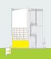
Sectional drawing of a medium-pressure membrane gas container

Medium-pressure membrane gas tank, storage volume 10,000 m³, operating pressure 70 mbar, location: Saldanha-Steel, South Africa

Medium pressure membrane gas tank, storage volume 1,500 m³, operating pressure 130 mbar, location: waste disposal Hannover-Lahe

Membrane gas tank, storage volume 1,000 m³, operating pressure 30 mbar, view of the membrane from the gas space


High pressure gas container
Today one uses almost exclusively high pressure storage (underground storage, pipe storage) for the storage of natural gas.
Spherical gas container

Spherical accumulators are the most commonly used type for medium-sized, e.g. B. for municipalities and industrial companies. The spherical shape allows the storage of gas under pressure. With a diameter of the steel ball of 40 m, a design for 10 bar gas pressure makes sense. One example of this is the spherical gas container in Wuppertal . The first memory was built in the 1960s; As a result of the higher pressures, their storage capacity soon exceeded the towering "gasometers". With thick walls up to 20 bar are possible.
Tube storage
Numerous municipalities use underground tube storage facilities to compensate for fluctuations in demand, in which the natural gas is stored at a pressure of up to 100 bar in parallel tubes at a shallow depth.
Storage in underground storage
Storage volumes of natural gas in the order of magnitude of a few 100 million to several billion cubic meters, which are required to compensate for seasonal fluctuations in demand, can only be kept economically in underground natural gas storage facilities. There are primarily two methods used for this in Germany. In cavern storage, huge cavities are created in suitable salt formations by brining, i.e. the controlled dissolution of the salt in water. When pores storing only a few microns wide pore spaces are used by sedimentary rocks. Former natural gas reservoirs are mostly used for intermediate storage, such as for the gas originating from the North Sea with intermediate storage in natural gas fields in Lower Saxony.
Tallest gas container in Germany
Highest gas container realized in Germany (see also list of gasometers in Germany )
| Surname | city | Height in meters | completion | Coordinates | Remarks |
|---|---|---|---|---|---|
| Gasometer Nordstern colliery | Gelsenkirchen | 147 | 1938 | Demolished in 1940 after being bombed | |
| Oberhausen gasometer | Oberhausen | 117.5 | 1929 | 51.494096 N 6.870672 O | shut down |
| Gas tanks from ArcelorMittal Eisenhüttenstadt | Eisenhüttenstadt | 104 | 1963 | 52.168789 N 14.632003 O | |
| Large Salzgitter AG gas tank | Salzgitter | 103 | 52.158297 N 10.401432 O | ||
| Stuttgart-Gaisburg gasometer | Stuttgart | 90 | 1929 | 48.788420 N 9.219367 O | |
| Gas boiler Augsburg | augsburg | 84.1 | 1954 | 48.387195 N 10.868397 O |
Revitalization of gas tanks


After the fall of the Western European mining industry and as a result of the increased use of natural gas since the 1950s, many of the now useless gasometers were demolished. It was not until the end of the 20th century that it was recognized that the gasometers, as architectural witnesses of a bygone industrial era, have a high cultural value. For this reason, attempts have been made at various locations to include gasometers in cultural projects, for example through exhibitions or sound and light installations. In the Duisburg-Nord landscape park , a diving club has installed a complete underwater world including a shipwreck in the gasometer.
The redesign of the four Viennese gasometers in Vienna - Simmering by the star architects Jean Nouvel , Coop Himmelb (l) au , Manfred Wehdorn and Wilhelm Holzbauer achieved international fame . The oldest and only preserved walled bell gas container in Berlin , the Gasometer Fichtestrasse , served as an air raid shelter during World War II . The listed building was converted into a residential complex with exclusive condominiums in 2007–2010.
Some Gasometer be used as exhibition spaces, such as the Gasometer Oberhausen , an anchor point of the European Route of Industrial Heritage (ERIH) or the Gasometer in Leipzig , Pforzheim and Dresden - Reick , in which the artist Yadegar Asisi so-called "Panometer" (a portmanteau of Pano rama and Gaso meter ) instituted in which large-scale panoramas are shown.
A telescope gasometer in Schlieren near Zurich was renovated as a technical cultural monument, and the operational preservation of the telescope mechanics (demonstration operation with air pressure) is unique in Europe. One of the best preserved Gasometer in eastern Germany is under monument protection standing "gas boiler" in Bernau . For a spherical gas container in Solingen , the conversion to the Galileum Solingen , a planetarium , is planned. The gasometer in Stade was converted into a multi-party apartment building with an integrated multi-storey car park as part of a renovation and structural expansion. In the German cities of Augsburg , Berlin , Dortmund , Leipzig, Münster , Neustadt (Dosse) and Zwickau , gasometers can be found that are still waiting for alternative use. The last two surviving gasometers in Stralsund were demolished in 2004, despite many public protests, as no investor had been found.
Gasometer for the chemical laboratory
As described above, gasometers for chemical experiments have been manufactured since the beginning of the 19th century. These devices are used to collect gases during chemical experiments and to transfer the gas to other containers. When certain inorganic salts or metals (e.g. sodium carbonate, sodium sulfite, zinc) react with concentrated acids or bases, gases are formed which can be stored in a gasometer. A gasometer in the laboratory area is a closed container that has a long tube that extends to the bottom of the container and the other end of which opens into a second upper container. In the lower container there is a tap that is responsible for the gas inlet or gas outlet. When the tap is open, gas penetrates the container from the outside and displaces the liquid in the container, which flows through the riser pipe into the upper container. After closing the tap, the gas is stored and can be released again in the desired amount. Water was often used as the liquid for simple gases, and mercury was also used in gasometers for very reactive gases.
Very simple, manageable gasometers have been developed for chemistry lessons in schools (e.g. by Phywe AG).
literature
- Dr.-Ing. Barbara Berger: The gas tank as a building type. Munich 2019, ISBN 978-3-95884-022-5 .
- Aug. Klönne: The largest gas container in the world, waterless gas container, DRP., Of 600,000 m³ of usable space, safe from mining damage, for the Gelsenkirchener Bergwerks-Akt.-Ges. Company publication, Dortmund 1939.
- Aug. Klönne: Flask gas container with a capacity of 50,000 m³ - DRP - for the Dortmund stock corporation for gas lighting in Dortmund . Company publication undated (after 1930).
- Disk gas container . MAN, company brochure, Dortmund 1958.
Web links
- Images of telescopic gas containers
- List with pictures of still existing gas containers
- Technology and function of gasometers in gas works
Individual evidence
- ^ Stadtwerke Nürtingen ( Memento from March 25, 2005 in the Internet Archive )
- ↑ Tube storage. Energie Wasser Bern (ewb), archived from the original on September 4, 2007 ; Retrieved September 27, 2007 .
- ^ Industrial monument Gasometer - Exclusive living and living in the Hanseatic city of Stade - Gasometer: Exclusive living and living in the Hanseatic city of Stade. Retrieved September 21, 2017 .
See also
- Wiktionary: Gasometer - Explanations of meanings, word origins, synonyms, translations
- List of gasometers in Germany